Beelbeebub
-
Posts
1385 -
Joined
-
Last visited
-
Days Won
9
Everything posted by Beelbeebub
-
I love airships but I don't think they are the answer apart from some very niche uses. The biggest issue is the slow speeds mean long cycle times. A 737 can cycle back and forth between London and Rome 4 or 5 times a day, so it's capital and operational costs can be split over many passengers. But the airship might do one leg, maybe a return with fewer people and the capital and operational costs would be similar if not greater than a 737. They do look cool though.

-
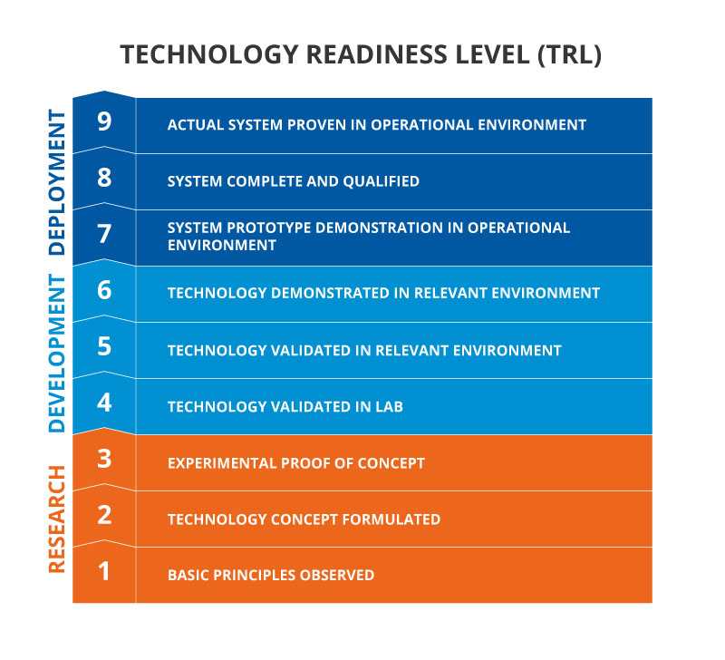
No it isn't - but I would put it lower down the list of priorities than the other two items. Those are bigger bang for your (political capital) buck. If we reduce demand for oil (and gas) from road transport there will be more oil available for things like flying. I'm not in the same camp as "just stop oil" - we will need to extract oil for the foreseeable future for chemicals and things where the intra high energy density is critical (mainly aviation, but also some critical "off grid" applications). I just think we should stop burning oil (gas) if we don't have to. Cars and HPs do need more generation and there are some swapping costs (though less if you just replace with electric at the end of normal life) - but again these are problems we have known "mature" solutions to. They are, in tech nerd speak, technology readiness level 9 "actual system proven in operational environment" Low carbon long haul aviation is TRL 4 at best with short haul at maybe 7 (there are some electric float planes operating in Canada for example) Absent some massive break though in creating hydrocarbons from electricity, water and co2 (which would also solve a whole bunch of other problems) aviation will be tied to fossil fuels for a while yet.
-
You can play all sorts of tunes with the statistics - do you count methane leaks in that gas heating stats? What exactly is the average uk house? How much worse are high altitude emissions? How do you attribute international flights? Etc. But the co2 emissions from flying are several times less than those from gas heating or private vehicles. Even if you 3x them to account for the altitude flying is only equal to one of those other items (in round numbers) We can definitely replace the majority of heating emissions now, today, with proven tech you can literally buy off the shelf. Likewise, we can replace the majority of cars on the road with EV equivalents that are availible today. There would be no major change to lifestyles or functionality. People would still have warm homes and still be able to drive about. (obviously both of those sectors will see a gradual phase out due to the relatively long life cycles of cars and boilers) But there is no currently available way to replicate the functionality of air travel without carbon emissions. Maybe one day there will be (fingers crossed). If there was I would 100% support swapping to that ASAP, in the same way I support EVs and HPs. But until then, I think we should focus on tackling the two sectors that are - much bigger than aviation - much easier - result in minimal disruption to people's lives. Otherwise we will alienate the public even more. The right wing press already bang on about "Greta stealing your holidays" or some such bollocks whenever any free taxes are applied to air travel. Imagine what would happen if we actually tried to ban air travel.
-
The average uk house with a gas boiler emiits 4-5t co2e a year. A full transatlantic return flight is about 650kg per person. So say 2 people and allow for lower average occupancy maybe 1t per person so 2t for your trip (4t if a family) You could swap to a HP, take your family on a trip to NY, and still be (a bit) lower carbon than staying at home and keeping your gas boiler. If you had an EV as well, you'd be well ahead.
-
I rarely fly, maybe 3x in the last decade, though I have flown to NZ once and the US a few times in my younger days. Incidentally my NZ trip took 24h all in. My grandfather visited NZ before the war to study farming techniques and other things. He went by boat. It took over a month. Without air travel International travel woill essentially become impossible for everyone but the super wealthy. If you focus on individual actions everything looks pointless. This is a variation on "the UK is 1% of emissions so why should we do anything". Say we wanted to cut our co2 emissions as a nation by 25%. We could totally ban flying. Nothing leaves the ground. No travel for business or pleasure. No fast cargo of goods. Nothing Can you imagine the public backlash. Holidays abroad, trips to visit friends and families, school exchange trips, sports tours, sports tournaments, academic conferences, specialist consultancy, music and arts tours etc all gone. And we would still need to do something else to reach the target. Or We could insulate our homes and swap to heatpumps. We would end up with warmer, cheaper to run homes that are less dependant on foreign fuels and easily meet our target. Or we could phase in EVs (and more rail) and have cleaner air in our cities, less noise pollution and also easily exceed our target Focusing first on air travel is like religiously turning off your TV at the wall each night to save energy whilst not insulating your loft.
-
Ha! I can see why you might think that but I'm not a carbon zelot. Being able to move things, including people from one side of that globe to the other in under 24h is a huge benefit. We should be minimising flying where possible. Eg, sub 500 mile (to pick an approximate distance) flights should be replaced with rail, business meetings that could be done remotely should be done remotely. But I would rather we saved carbon by moving to EVs and heatpumps and continue flying (albeit maybe at a slightly lower rate) rather than cut flying so we can drive ICE cars and use gas boilers. And we would save *much* more carbon by doing those things (and improve energy security) than by stopping flying all together.
-
Whilst air travel does ha e a carbon footprint it also has massive benefits. Without it intercontinental travel, especially between the America's, Australia and africa/europe/Asia would become almost impossible for the average person. It would become the preserve of the ultra rich who could afford to take 2 weeks or more to travel each way. I would point out that the carbon emissions of uk domestic and international air travel (I know attributing carbon to a territory is tough but there are various estimates) is around 40MtCO2e The emissions from passenger cars is about 60MtCO2e and residential heating is about 50MtCO2e So we could decarbonise (electrify) passenger cars and heating (Ev's and heatpumps) and carry on flying.
-
UK ‘built for climate that no longer exists’
Beelbeebub replied to SteamyTea's topic in Environmental Building Politics
+1 on the overhangs, a good foot or more. Defo, oversize the gutters. The current regs are based on historical norms. We've had several "monsoon" downpours already that have overloaded standard gutters. We used large (150x150 irc) square extruded aluminum ones. Interestingly we set them "in plane" with the roof. Ie at 30 degrees (for our roof) so they acted as "V" gutters. Minimise south-facing glass or provide externalnshades/shutters. My old house had very little south facing and I was glad of it. The "winter sun heating" didn't really happen as our winters tend to be gloomy. Every time I see a grand designs with a south facing curtain wall or giant windows to "catch the sun" or similar I wince. Cross ventilation, and also up and down ventilation if multistory. Defo level access (be aware of flooding!) and don't forget wider doors for wheel chairs etc, if you can. We did this and it was a godsend when we swapped with my parents when my dad got dementia. The buikding regs already spec higher sockets and lower light switches. It seems odd at first, but - again is a massive plus for any one infirm. Even an able bodied person can get temporarily injured (back or arm injury) and these things help then. On that note, the front door lock shoukd be accessible - the traditional rim lock is often at shoulder height which makes it difficult if you ha e a shoulder injury and crucially (my parents learned this the hard way) avoid any door setup that requires 2 hands to open. Specifically a door knob and yale lock combo. My mum broke her arm and could get into her house on her own for a month. Even now it's right pain carrying stuff back in from the car. (sorry rant over) No smart stuff. -
This is clutching at straws a bit. In the actual report they call out that renewables have lowered the daytime price putting downward pressure on the cap and the quote was from the regulator itself so one would assume they are aware of the context. But if we wear our steixlty logical hat - whilst we cannot say that a rise in renewables certainly lowers prices we can say that a rise in renewables does not invariably lead to a rise in prices. In fairness they do also say that the loss of revenue for thermal plants during the daylight hours means the costs have to be put into the price of thermal power when it is needed pushing that bit up. They also note that a drop in the Lng prices in late 2025 helped lower wholesale costs, though that has now been reversed. They say that grid scale battery systems are starting to mitigate those fluctuations by providing a customer during daylight to recharge and providing cheaper than thermal power on the evenings further displacing thermal power. Bear in mind the displacement of thermal power during the day doesn't markedly increace the fixed (capital, depreciation etc) costs of thermal power it just concentrates them into a smaller output. So the overall cost of having a thermal plant on the grid is roughly the same regardless of it running or not, so it's not true to say the intermittency makes it more expensive (beyond some increace in maintance and fuel burns for start/stop running) overall. If it costs you £100m + fuel to keep a plant up and ready it is still cheaper to run it once and get low cost elec the rest of the time than to run it 365 days a year. Again, the report explicitly calls out the rise in the price of coal and gas on the international market as historical upward cost pressures and not the increace in renewable generation. Despite being a big exporter of coal and gas the thermal plants have to compete with international buyers so when coal jumps up the cost per Mwh from an Australian coal plant burning Australian coal also jumps up. There will be inevitable challanges and it will not be easy. But we need to get away from the narrative that there is a sensible choice between doing it and just staying as we are and lowering prices by drilling.
-
My understanding was that the high voltages are occurring away from the sub stations and out on the local network. Imagine you and your neighbour were both fed of a single extension cable plugged into the substation down the road. If you both export 5kw each, during the day the total is 10kw down a little B&Q extension cable. And if you both consume 5kw each that 10kw has to flow back up the cable. Putting a battery to absorb that at the substation wouldn't help the poor extension cable. 10kw would have to flow down during the day, and 10kw back at night. But if you both had battery packs capable of absorbing the power during the day and giving it back at night, the cable would see 0kw - essentially you'd be off grid.
-
Whilst solar has obvious advantages in Australia, the UK generates more from renewables (125Twh vs 100Twh) and Australia has a lot more distance for grid infrastructure.
-
How would they stabilise the voltage? As I understand it the voltage spikes and sags are more related to the lines between the house and substation. The voltage at the substation is much more stable than the voltage at the homes and jas to be set so that, at max draw, the furthest property is still above the legal limit. Unfortunately this means when there is zero draw the voltage is already high and if that hose starts to pump power in, it rises higher *at the house* so their neighbour sees higher voltage too. A battery at the substation wouldn't be able to raise or lower the voltage by much or for very long. Lowering the grid voltage to 230 rather than 240, which I believe they are doing, would help. I did see some plans for "solid state transformers" which looked to be giant inverters to change the voltage output up or down on real-time. Traditional ones can do so via changing the tapping on the winding but that is normally a maintance task. These could lower the substation voltage when generation was high so the max voltage on the network was on limits and then, when the power is demanded, raise the sub station voltage to ensure the min voltage on the network is above the limit.
-
But batteries at the substation won't help with the last mile of transmission. Pretty much by definition they are at thr junction between the low (relative to grid voltages! 😁) 240v system and the higher transmission voltages. If DNO's wanted to reduce the peak loading on their local network and avoid having to upgrade - then that might be an incentive for them to put batteries in customer's houses. But I'm not sure shirt term peak loads are that much of an issue for DNOs because of diversity. Their problem might be the sustained medium loads that never used to exist eg heat pumps and car chargers. That said, if you have an electrically heated street or estate, it would have been the case it would be sized for a sustained storage heater load overnight from everyone. So 4 or 5kw per house overnight. If you swap that out for heatpumps your load drops to maybe half or even 1/3 continuous. Which leaves the rest availible for charging cars overnight.
-
That may be a technically and economically better solution, but it may be difficult to create the incentives for that to happen. The hardware needs to go into the substation area, which is owned and operated by thr DNO, who has no interest in the consumer or the wholesale market. The energy Co doesn't have access to that facility. Putting the batteries at the consumer's end is, whilst less economic, much easier - especially if it's just shipping a box to the consumer who plugs it in and connects it to WiFi.
-
I think the plug in battery systems might end up being the better solution. A 1 or 2kwh plug in unit - especially if linked to time of use tariffs - could make a big difference to bills and the current 4-pm demand peak. I keep thinking that octopus or similar could offer a tariff where you get a plug in battery and got a guarenteed low price for Xkwh a day. Say you pay £1 a day all in for 5kwh with the rest charged at normal rates - maybe a roll over/forward facility up to 10kwh in a single day. The energy supplier would make their profit by charging the battery at cheap periods and thus reducing their volume a at high price periods. If such device were just a suitcase sized box delivered to your door, connected to WiFi and plugged in somewhere it could get really good uptake.
-
https://www.aer.gov.au/news/articles/news-releases/aer-releases-final-default-market-offer-2026-27 If renewables are going to make the grid more expensive how come they are making it cheaper on Australia? The combined range of price changes (flat rate and time of use) are: New South Wales: Residential -3.4% to -7.7%, Small business -9.0% to -20.9% South East Queensland: Residential -7.2% to -10.7%, Small business -10.4% to -14.0% South Australia: Residential -1.1% to +1.4%, Small business -6.8% to -12.1% AER Chair Clare Savage said.. “The reductions compared to last year reflect easing costs across most components of the DMO, particularly in wholesale energy, where we’ve seen lower electricity contract prices, reduced spot price volatility, and increased output from wind and battery generation during evening peaks.” “Despite uncertainty created by conflict in the Middle East, wholesale energy costs have not increased.” Of course australia did see diesel almost double before falling back to (currently) about 25% more than pre war levels which is painful - but underscores the advantage of switching transport away from fossil fuels.
-
I see this point come up alot, but wouldn't it only apply if the person overloaded the circuit to begin with? If you have a standard ring on a 32a breaker they can run several appliances together, say 3, up to the 32a limit, but the typical 2.5mm cables are only rated for 20a and the whole concept relies on both ends of the ring taking the load so no one part ever sees more than 20a. A person could run more than 32a of load if the additional current was provided by the solar but as long as the wiring run from the solar to the load wasn't exceeding 20a it would be fine. So a tumble dryer plugged into the same double socket as the solar would be fine. The problem might occur if the loads and sources were too far apart or unbalanced but that is a statistical risk the ring main system accepts anyway.
-
there are premade rubber cable entry "patches" for cable and pipe entry.

-
Yes, this is (I think) more of a modern problem. In the past our politicians were somewhat more serious. You may disagree with various historical politicans and they may have made disastrous decisions and mistakes but it seems (at least in hindsight) that they took the job of being a politician seriously. They would sit for hour long serious TV debates where they would delve into complex matters. The interviewers and opposition acted in good faith and followed up. Look at the TV debates of the 70's and even 80's. The vast majority of government work carried out by the professional civil service and their advice was taken seriously. This was why someone with no particular ecperice ofnhealth/defence etc could fulfil the role. Now, as mentioned, politicans don't act in good faith. It's all soundbites, misquotes and blaming the "deepstate" for stopping you doing what you want to do (mainly because it's a massively stupid thing to do). One of the Trump appointees - possibly homeland security, recently floated the idea of cutting the number of federal customs and border staff at airports im cities that weren't cooperating with ICE. At the time everyone thought it was just some off thr cuff remark because to cut staff at NY, Washington etc airports - some of the biggest in the US, would cause absolute carnage with most of the economic fallout being borne by the cities that the travelers were eventually heading for rather than the ones they first landed in. Anyone with an ounce of understanding of international travel, tourism etc would contemplate such a scheme. Anyway, it looks like they might be serious.... Because Trump's primary criteria for appointments is personal loyalty rather competence.
-
There's an intersitn flip side to this which is the tendency of people who are really skilled in a given area to not think of their skill/knowledge etc as exceptional and think everyone else is of a similar ability. This is what sometimes males excellent skiers, artists, scientists etc bad teachers. "you just bend the knees and turn the skis!" they shout at their poor student. It's can also lead to disastrous political consequences when politicans, who may be immersed in a complex and counterintuitive policy area, put questions to the public assuming the answer is obvious to everyone.
-
I remember when diesels were slow, noisy and heavy.
-
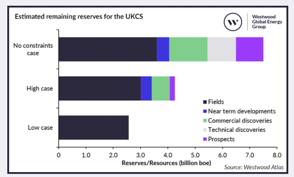
That graph is by the oil industry. It's including absolutely everything they suspect might be out there. It includes unknown discoveries ie fields we don't even know exist yet and even unknown improvements to extraction technology to get more oil than we think we can at the moment. And even then, after all that optimism, production still falls 50%. The question of whether or not the costs of extracting that last little bit of oil are worth it or not is seperate from the question of what good that little extra bit will do.
-
This is the point ☝️ Some politicans are selling the idea that the UK could be Saudi Arabia or texas if only thr "woke" politicans would get out of the way and allow the oil companies to drill, lower our bills and increace our energy security (out of the goodness of their hearts). It's bollocks. Our high energy prices and energy insecurity would not be made better by all the drilling in the world and the very things that will help are opposed by the same politicans.
-
Could you dm some details?
-
They are included in the Westfield report which has a wildly optimistic "no constraints case" case. And even that case has production falling by 50% from today's figure by 2035. For reference their low case (2.5bn) is less than the NSTA central estimate which is about 3.5bn. So their high case is maybe 1bn (4.5bn) more than the current official estimates.