


SimC
-
Posts
20 -
Joined
-
Last visited
SimC's Achievements

Member (3/5)
10
Reputation
-
Considering scaffold tubes for a ground mount.... thoughts?
SimC replied to TedM's topic in Photovoltaics (PV)
@TedM, In your latest photo, is that shading by the wall of the lower right corner of the furthest panel? This will reduce the performance of the whole string at that time of day. You seem to have around 0.5m of spare frame to the left of the panels, so could they not all move over, or are there other shading issues? -
Quote for 7kw Vaillant - surely not enough?
SimC replied to Michael_S's topic in Air Source Heat Pumps (ASHP)
If the physical space for a cylinder is the issue, have you considered a Heat Geek MiniStore? They are available in a number of sizes and can have an immersion fitted for a small uplift in price, though there is a price rise coming from 1/5/2026. The current v1.4 MiniStore can have a +100 mm section fitted at the bottom with an immersion. It will not store enough for 6 showers, but will achieve a higher COP than the existing cylinder and will recover quickly following a shower. -
The flow/pressure chart makes much more sense now with the labels on each axis. Yet you need to be achieving 2095 l/h at 100% pump speed, and according to the the chart you only have around 55 kPa available external to the HP. So a higher flow rate is required, with a lower pressure drop, which is a significant difference to make up with pipe changes to larger diameter and a reduction in the number of 90 degree elbows. From your photo of the rear of the HP, I can see 4 elbows, and assume there are another 2 elbows to direct the pipes through the external wall. These pipes are not well aligned with the ports on the rear of the HP, and once lagging is applied will act as an obstruction to air flow from the rear of the HP to the front. This area could be significantly improved with the suggested larger diameter flexible insulated hoses. With such a flow/pressure difference to make up you may need to be looking at some of the heating pipes after the diverter valve as well. May be think of what flow rate is required down each section of pipe to assess suitability of the current sizing.
-
Assuming the pump is performing correctly at 100% speed, yes you can use the chart to lookup the reported flow value to determine the pressure generated by the pump. I would have expected the Vaillant technician to have measured the pressure drop of the HP heat exchanger, or at least the residual pressure difference between the flow and return connections to the HP unit with the pump running. The 70 kPa developed by the pump is all lost across the whole circuit including the HP heat exchanger, so if the heat exchanger loss is say 25 kPa then only 45 kPa is available to generate the required flow in your heating pipes and emitter system. The published Vaillant manual should at least provide the expected HP HEX pressure drop at design flow rate, and the residual pump pressure for your system. My work involves interacting with air and water balance specialists usually in commercial buildings who validate by measurement with calibrated instruments that a system is performing as per the design criteria. By just relying on a unit display value, and not by seperate measurement, Vaillant have not proved that their unit including pump is actually performing to specification. Obviously you have also highlighted concerns with sections of the distribution pipework sizing, that should also be resolved to improve the resulting flow rate when heating, but you could be chasing your tail if it turns out there is an issue with the pump not actually generating 70 kPa pressure.
-
At 1750l/h we have a pressure of 70kPa. Where was the 70 kPa measured? If across just the pump, what was the pressure drop across the HP heat exchanger?
-
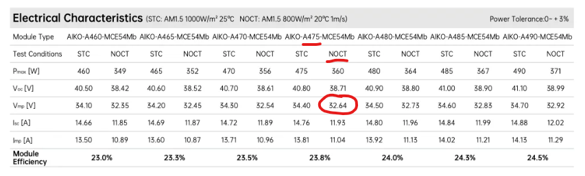
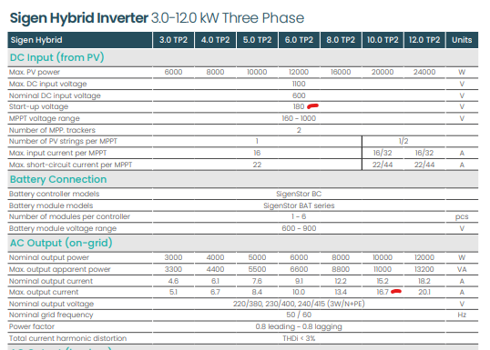
There may be an issue with the 3-phase Sigenergy inverter combined with the 4 panel string, in that the MPPT startup voltage is stated at 180 Volts. In comparison the 1-phase inverters have MPPT startup at 50 Volts, but only size up to 6 kW. The Sigenergy datasheets and install guides provide no information on how the 3-phase unit reacts to unbalanced loads. If the inverter only outputs equal power on each phase when there is an unbalanced load, then the net result is that some phases will be importing from the grid and some will be exporting, rather than all 3-phases being grid neutral. It is not clear whether any specific 3-phase grid meter from a supplier operates with net metering calculations or not for billing purposes. With the 10kW 3-phase inverter, the max output current per phase is 16.7 Amps, which equates to just over 3.6 kW on each phase. If your loads draw more than this on a single phase, then the remainder will be imported from the grid. The Aiko NeoStar 3S 475 W panels will probably only produce around 30 V each in lower light conditions, which only produces 120 V when the 4 are connected in series. This string input is unlikely to start even in the brightest conditions, so is not worth installing with the proposed equipment. These observations may not provide a solution for you, but I hope they are helpful in what to look out for when choosing a new system.
-
I am interested in how the specific PHE was chosen. Was it based on kW rating, water flow rates required by the boiler and CHP, or some other arbitary parameter? My experience in a work capacity is that the primary and secondary return temps are very closely matched at low flow rates, but when the flow rates increase there is a point when the primary return temp (to heat source) rises significantly which has a knock-on effect on the heat source efficiency.
-
In theory it could be possible to add an ASHP in parallel with an existing boiler, but both would need to have their own pumps in the correct part of the circuit, and each have a non-return valve to prevent reverse flow through the non-running unit, and the existing plumbing would have to support the required flow rate through the ASHP, and the water teatment used would have to suit both. So quite a lot of dependencies. My 8mm microbore to most of the rads will probably not allow the required flow rate for an ASHP, and I have no idea what water treatment would be required to suit both devices. Thinking about inserting a plate heat exchanger, but then the issue becomes the ASHP does not engage with sufficient volume of water for de-frost cycles etc. The Daikin hybrid schematic does not indicate where any pumps are located to generate flow, so they could be in series, meaning the non-running pump will restrict the whole system flow rate.
-
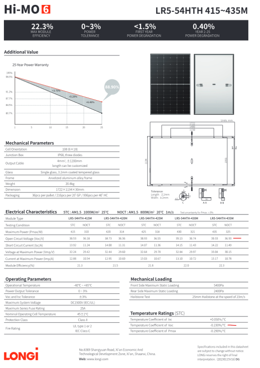
Another significant parameter is the current under STC and NOCT conditions. As the new and old panels will be wired in series for each string, the same current value will pass through all the panels in a string. The best match will be if the new and old panels would naturally produce the same current at the various insolation levels say 200W/m2 to 1000W/m2. Some manufacturers show an insolation/current/voltage graph on the data sheet, but not Longi. Have you got the full data sheet for the existing panels? Current of the new panels, Imp = 13.17 A (STC) and 10.78 A (NOCT). The string voltage is then the summation of all the panels in that string which must not exceed the capabilities of the inverter, even under open circuit conditions at low temperature (Voc - (Voctempco * (25 - - 20 degC)). For the new panels this equates to:- 39.33 - ((-0.23% * 39.33) * (45)) = 39.33 + 4.07 = 43.40 V per panel.
-
Mini Store - Heat Geek / Newark Cylinders for ASHP
SimC replied to Nick Laslett's topic in Air Source Heat Pumps (ASHP)
I would be interested for thoughts on using one of these to convert from a vented hot water cylinder fed by a system boiler via a 3-port diverter valve to a hot water system under mains water pressure. Presumably it avoids the full G3 requirements as the hot water coil must contain less than 15 litres volume within the pressurised circuit from non-return valve to closed hot water taps. Does the G3 requirement for a pressure/temperature relief valve and associated drainage then go away? I already run the boiler at around 50C flow temp for heating, then turn up to around 70C on 1 day per week to heat the full tank for bath day. The remaining 6 days use an Eddi plus immersion for night/solar hot water heating of just the top half of the tank which is sufficent for showers and washing up. Presumably with the MiniStore the boiler flow temp would not need to be so high, and the 15 kW boiler would be able to provide enough top up to be able to fill a bath. The current hot water cylinder is approx 1100 H x 475 D, the same as the Tall MiniStore. Just trying to think outside the box with immersion backup possible by using a Willis heater connected between the heat source flow and return connections to the MiniStore. The existing boiler system is already vented with expansion up to the loft header tank. -
Clean Heat Market Mechanism to incentivise heat pumps
SimC replied to LnP's topic in Air Source Heat Pumps (ASHP)
The PVGIS default value of 14% system losses are not all down to conversion and transmission losses, a proportion is due to the degrading performance of the panels as they age over their lifetime. Many panels are rated at 98% after year 1 and down to 86% at year 25, so you could assume a mean value of 92% (8% loss) over the lifetime. Here is the relevant extract from the PVGIS user manual.
-
It does not seem to be best use of hydrogen in a fixed location such as a distillery. Electrification would in my mind be a better solution, and not reliant on a single source of supply of hydrogen. In my day job I have come across a few recent examples of cascaded ASHP and WSHP in order to achieve suitable grade heat for hospitals including for their DHWS which is required at least at 60 C for protection against legionella in areas for vulnerable patients. This must be somewhere near the grade of heat required for distillation.
-
My concern would be how to modulate/balance the water flow rates through the currently active heat source with that through the total of 5 pumps serving the loads. There would appear to be a total of 7 pumps required in the system, assuming 1 in the outside ASHP and 1 in the system boiler. Too low a flow rate through the heat source, and the manifold ends up containing predominantly cool return water from the loads so not meeting the load heating requirements. Too high a flow rate through the heat source, and the manifold ends up containing predominantly hotter water from the heat source resulting in a high return temperature to the heat source with its knock on effect on the COP/efficiency.
-
You could have an 8kW inverter with a 3.68 kW DNO export limit. How any inverter achieves this is by having it's own metering device next to your utility meter (or along the route of the main live cable from the utility meter). The inverter then has a live import/export power value that can be limited to whatever value is programmed in. The value is password protected so that only the installer and manufacturer can set or change it. The inverter has power point trackers on the PV string inputs, that it can set for maximum/optimal output from the panels, or when the export limit is being reached the trackers adjust to non-optimal to reduce the electrical power output of the panels. The excess solar energy is then just dissipated as heat in the panels. Solar panels are only around 20% efficient at generating electricity, so already dissipate 80% as heat meaning another few % due to the DNO export limit is not going to cause any damage. Have you got a logical position for the inverter and batteries, bearing in mind there needs to be suitable cable routes for the DC feed from the panels, the ac power cable to a suitable consumer unit breaker, along with a data cable to the metering device? Batteries are very heavy, so ideally on the ground floor. Depending on your building layout, a garage can be the best location, but only you know the layout.
-
One solar performance website is:- https://re.jrc.ec.europa.eu/pvg_tools/en/#PVP Here is one example of a thread from this forum (the advanced search with 'wall pv' is your friend).



