Dunc
-
Posts
210 -
Joined
-
Last visited
Everything posted by Dunc
-
Another MBC build here. No soil stack through the roof (have a separate branch outside to do the venting bit and an air admittance valve at the top of the stack internally to do the anti-vacuum bit. Is that an option for you?). However, as Nick above, we have MVHR ducts and terminals penetrating the inside membrane in the upstairs ceiling (i.e. the airtight layer). Brendan taped them all up no problem at all and the building achieved 0.3 ACH. On that basis all you would need to worry about is your roofer getting a watertight (rather than airtight) seal on the outisde.
-
I belive gutter capacities are calculated, rather than intuited, including specifications for rainfall amounts to BS EN 12056-3 e.g. https://www.floplast.co.uk/you/diyinstaller https://alugutter.co.uk/pages/gutter-drainage-performance-eaves-gutter-design-bs-en12056-3?srsltid=AfmBOopwXxj1pTu7ASOsX0Hc1K2cJz8FK6ftk4oQ8J6iE5rW0462CgPn
-
Insect mesh and air gap for timber cladding?
Dunc replied to Great_scot_selfbuild's topic in General Joinery
Our air gap is defined by the counter battens - 22mm. I used stainless rodent mesh 8g from Robinson wire cloth - more worried about mice than bugs round here. 150mm x 30m rolls worked well. I did try keep some gap around window head and cills but with the way it went together its probably onlt 5mm at best. Like you, I trust lateral movement of air will be sufficient. https://timberdevelopment.uk/resources/the-timber-cladding-handbook/ Worth a read. -
New balls please... Lots of ideas and options, thank you all!
-
Ah. I took that first point to refer to a single, isolated pipe (although I realise "isolated" isn't defined). Perhaps I was being distracted by tge "not more than 4" in the second bullet. Just concerned that effectively with the manifolds I'll end up with a slot at least pipe diameter (15mm) x 325mm, plus clearance, which may not be acceptable to BC.
-
Just need a sanity check please: Fire stopping is required for service penetrations between separating floors (Scotland, Domestic Tech Handbook 2025, 2.2.9, p88). Exceptions are listed which seem to cover most of the requirements for single domestic dwellings (exerpt below). However with radial plumbing I'll end up with 21 plastic pipes of 15mm diameter from the manifolds heading up into the ceiling void before dispersing to outlets. Of course these pipes will basically be in 1 group in order to connect to the manifods. The forum is full of examples of mainfold based plumbing, so have I missed something in terms of the fire stopping, or the exemption? Fire stopping of the following services passing through a separating wall or separating floor need not be provided for: • a pipe or a cable with a bore, or diameter, of not more than 40 mm, or • not more than four 40 mm diameter pipes or cables that are at least 40 mm apart and at least 100 mm from any other pipe, or • more than four 40 mm diameter pipes or cables that are at least 100 mm apart, or • a pipe which has a bore of not more than 160 mm and is of iron, steel or copper, or of a material capable of withstanding 800 ºC without allowing flames or hot material to pass through the wall of the pipe, or • a branch pipe of a bore of not more than 110 mm connected to a vertical drainage or water service pipe, constructed from aluminium, aluminium alloy, or uPVC to BS 4514: 2001.
-
We're aiming to lay wood plank effect porcelain tiles 1200x200mm over approx 100sqm ground floor. Any tips, tricks or things to avoid? @saveasteading I think you had some photos of similar a while ago (can't find in the forum search). Did get some quotes from professionals but with one guy asking £80/sqm I think we'll be taking it on ourselves. Key questions is trowel notch. The guys we've had quote have differing ideas with a range from 6-12mm notch (resulting in 3-6mm adhesive) which obviously affects final floor level. For Ditra mat, what notch? Any suggesions for a diy roller for the mat?
-
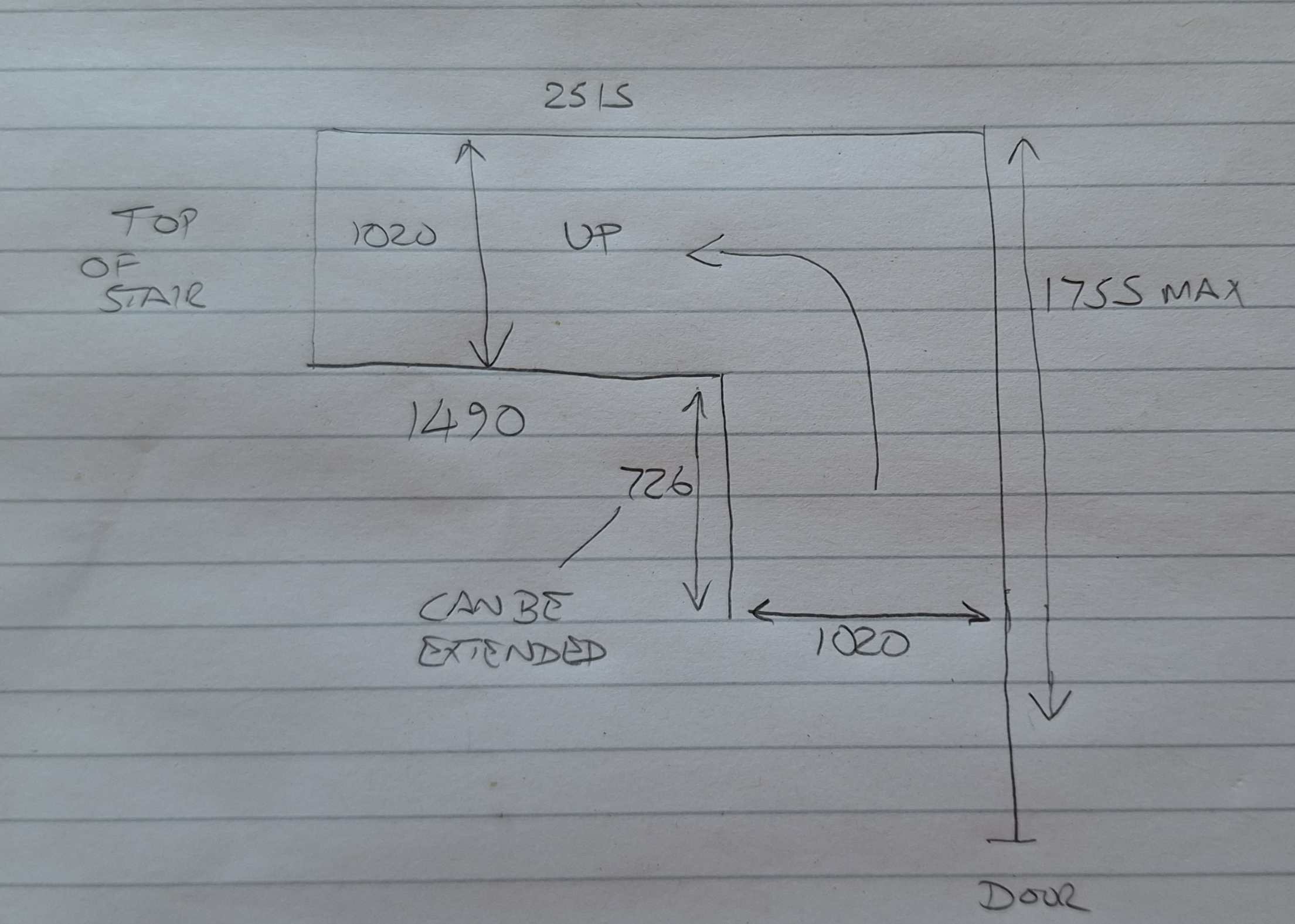
Yes was hoping to install the stairs myself.... Yes, stud walls are full height and already in place because they are structural racking. Only the stub wall is not structural. I suspect that one at least will have to come out. I'm reassured that I haven't missed something obvious!
-
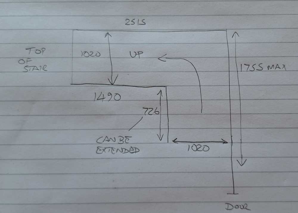
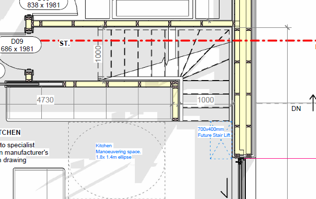
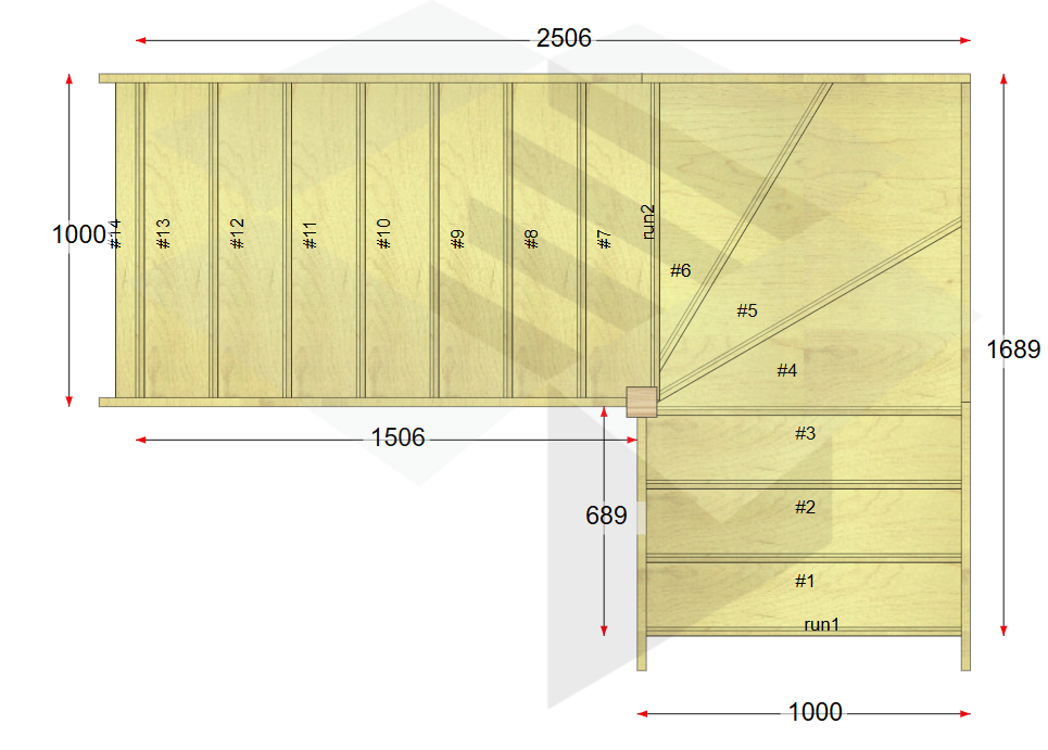
I need help understanding how a winder staircase can be installed in a fully-enclosed stairwell, please. CAD drawing shows the as-measured openings between stud/structural walls. Architects plans for context also attached. Stairbox have suggestd an over-stringer width of 1000mm which in principle fits with 20mm tolerance. However, the newel post at the inside corner of the winder overhangs the stringer by 29mm which means it doesn't fit between the walls. They suggested trimming back the studs on the inner corner to set the newel post into the wall. But I can't see how the stair would be constructed and inserted into the available opening as the newel post would have to pass all of the other studs first if the upper run is installed from the first floor with the post attached (which I belive is how it's usually done?).
-
I need to install the MDPE water pipe from my boundary box to the house. There is no option but to have it under the driveway, which will be gravel over MOT. I'll bury the pipe at least 900mm down. Should I use a duct in the bottom of the trench, or will a bit of sand under and over the pipe be sufficient? Ta.
-
+1 on the Huepar. I was a bit shy of spending so much money, but I've found it to be a very useful tool so far in the build. Way better than a single-line red DeWalt I had borrowed initially.
-
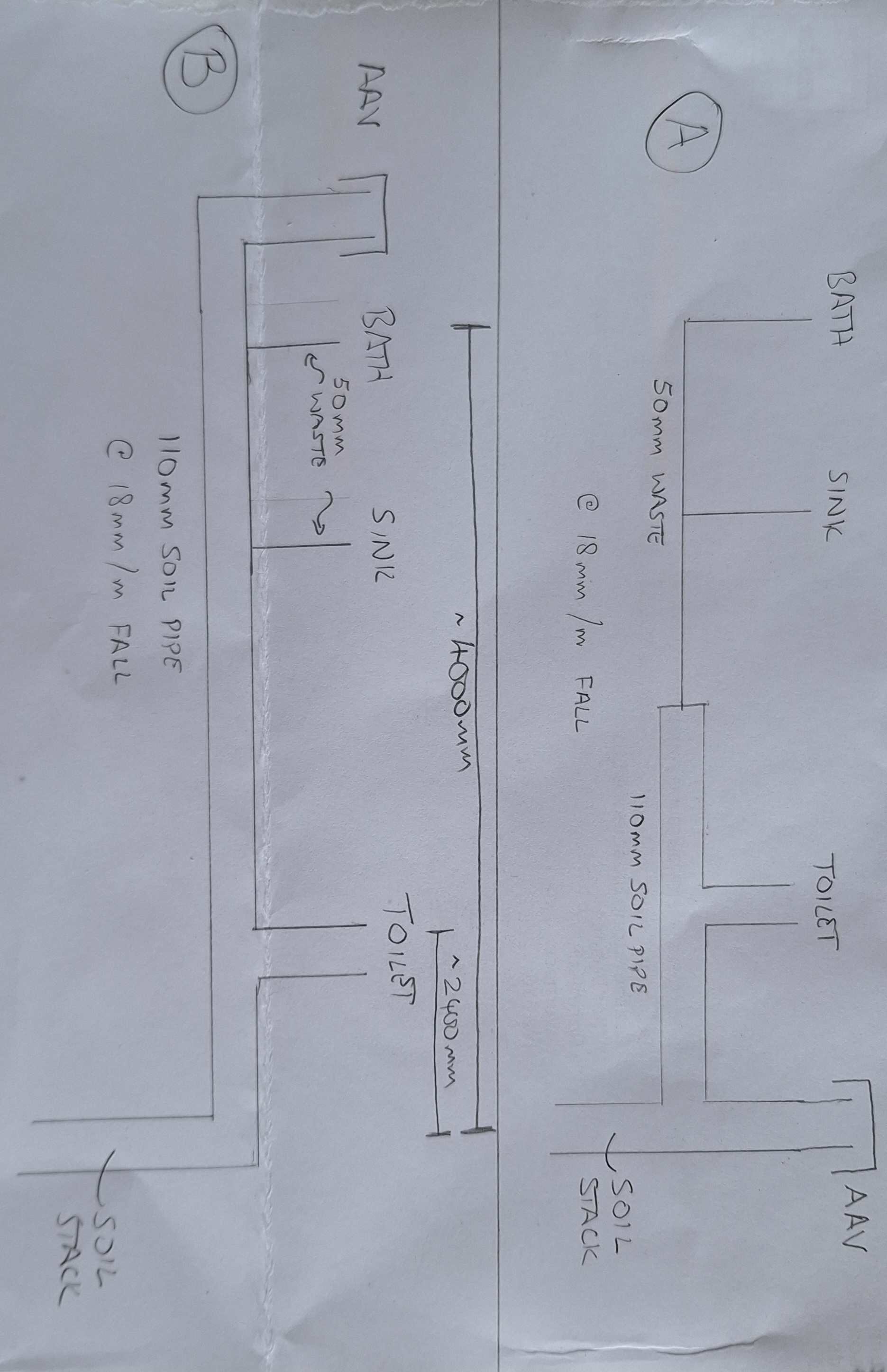
To be clear @Nickfromwales whichever scenario is used, the soil stack and AAV (and everything else in the drawings) are indoors on the first floor - the soil stack does not penetrate the ceiling or wall here it just drops to below the slab and exits there. Hence the requirement for the AAV inside to let air in. Gas venting is outside. Access not a problem as this is all in a service coomb behind a false wall. Does this change your view of Option A?
-
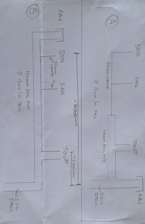
In the upstairs bathroom I have bath, then sink, then toilet running "horizontally" (18mm/m fall) into the vertical soil stack. I need to install an air admittavce valve for the stack. Venting is provided separately, outside the house. If I install as in (A), in the highly technical drawings below, is there risk that the bath and sink would be vacuumed by the toilet flushing? Would (B) be a better arrangement?
-
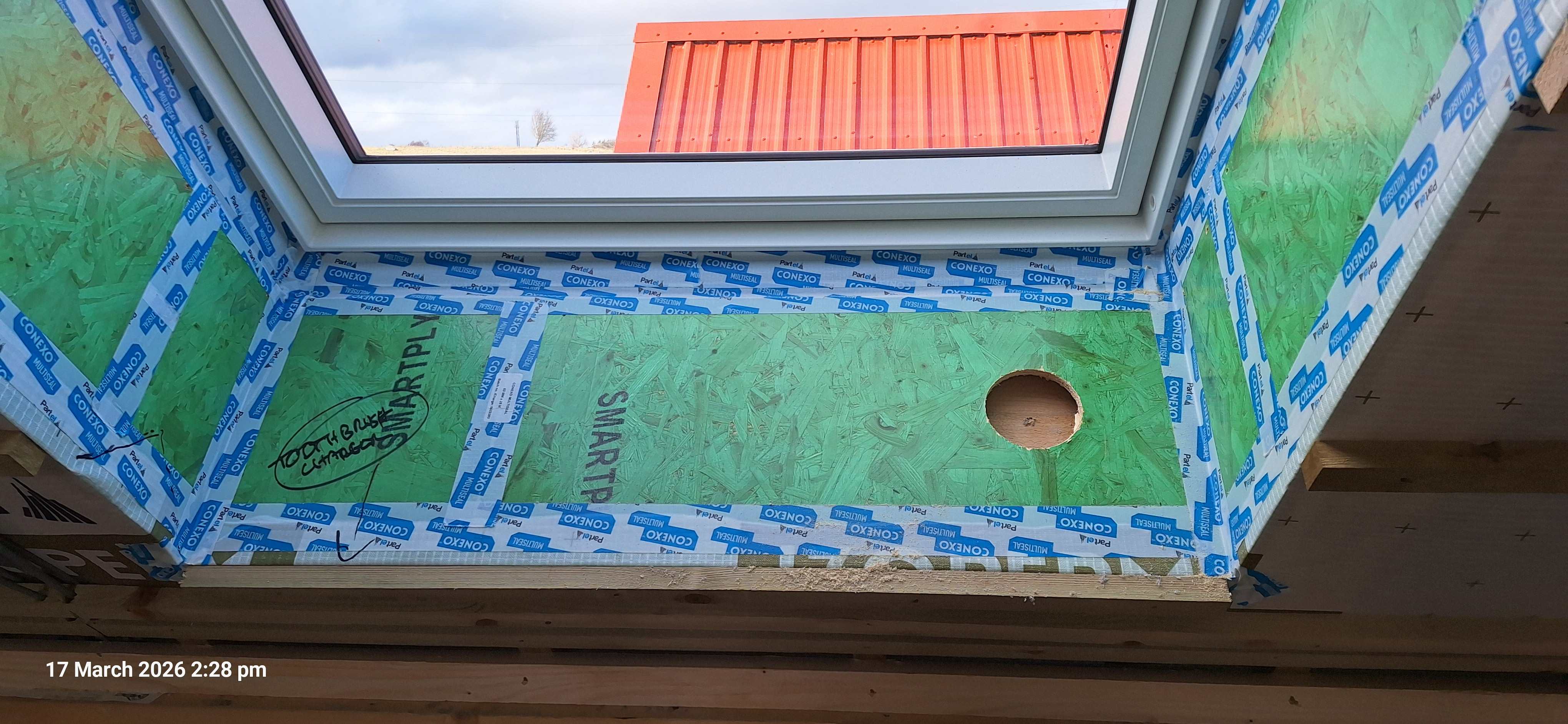
Two good suggestions there, thank you! I take it you agree it's worth sorting, rather than ignoring. I guess the squirty foam might be easier. Getting the osb off, having already been thoroughly taped up would be difficult. The tape tends to rip the green layer off. Is all expanding foam equal? Not sure whether the expense of the illbruck airtightness foam is necessary, being on the outside of the airtight layer?
-
The cellulose insulation was pumped into pur larsen truss frame last week. The installer noted that at each velux window there is a small-ish gap between the head and foot trimmers and the airtightness board about 25mm. Not possible to pump cellulose into such a shallow void. There is insulation behind the trimmers, of course. The TF company have dismissed the gap as "too small to have any impact"...I'm disinclined to accept that when chasing marginal gains in Passive type builds this is a reasonable thing to ignore. Am I being unreasonable? If not, suggestions for a solution?


-
Scotland - north east highlands. Not sure they're local; think they're travelling from Essex!
-
MBC are using R.Warville (JW- Insulation.co.uk) for my insulation blow next week.
-
Dunno if it's in the spirit of the forum to disclose company names? @Buildhub Moderators can delete if required. These are windows from NordVest. Have checked warranty detail. 2 years parts & labour, 5 years glazing & labour; further 5 years glazing but no labour....just shows how variable warranty can be. Perhaps I should have looked into this in more detail when choosing a supplier. But the headline "10 year warranty" seemed comparable with others. Doesn't fill me with joy for the long term. However they have accepted the warranty claim with fairly minimal fuss (a surprise based on previous issues). So new glass is on the way.
-
Dunno if it's in the spirit of the forum to disclose company names? @Buildhub Moderators can delete if required. These are windows from NordVest. Have checked warranty detail. 2 years parts & labour, 5 years glazing & labour; further 5 years glazing but no labour....just shows how variable warranty can be. Perhaps I should have looked into this in more detail when choosing a supplier. But the headline "10 year warranty" seemed comparable with others. Doesn't fill me with joy for the long term.
-
When we were getting quote, cost difference between 2g and 3g was about 10% from the same manufacturer in my case. Much smaller than expected.
-
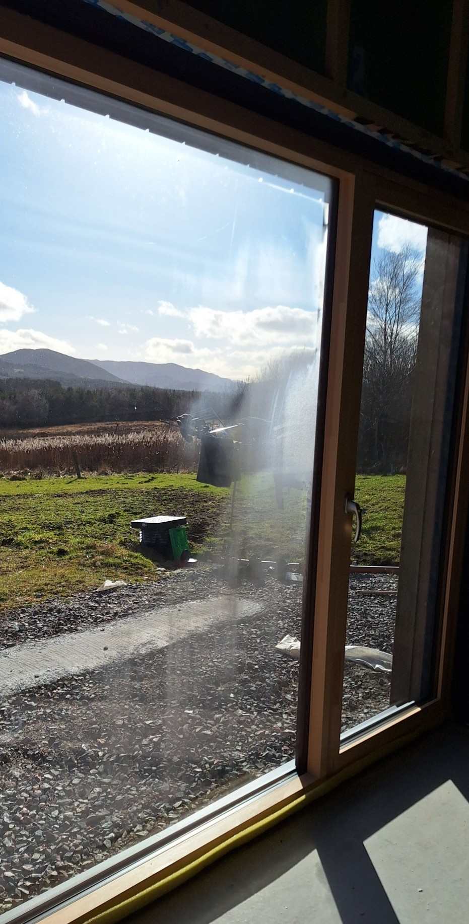
My timber cladding reveal boards overlap the aluminum of the window which itself ovelaps the glazing unit - they'll have to come off unfortunately. Doable, but irritating given I only finished installing today.
-
Not bl**dy long enough 👿
-
Well that's disappointing to say the least. No end of trouble with these windows. I really wish we'd gone with another manufacturer. Installed by their "recommended" installer, so not a direct link there. But at least we know I didn't mess it up. Will have to check the warranty to find out who's paying for the labour. Rather gutted as we just finished cladding that side today. The timber in the window reveal will presmably have to come out to allow access. There just aren't enough swear words today 😡
-
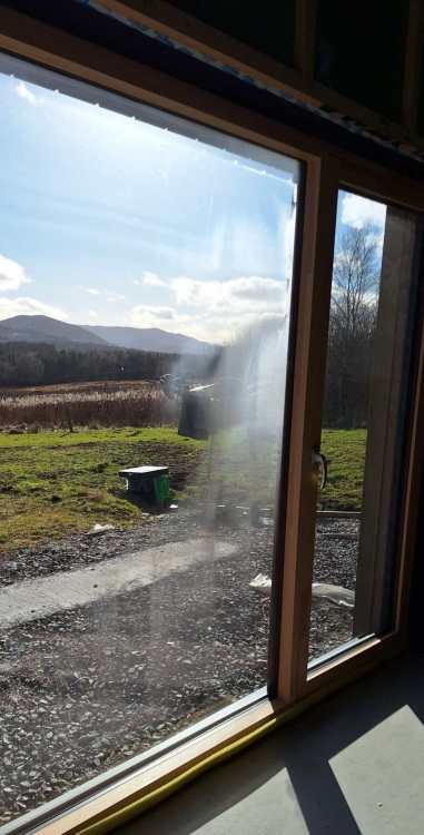
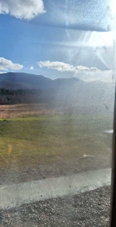
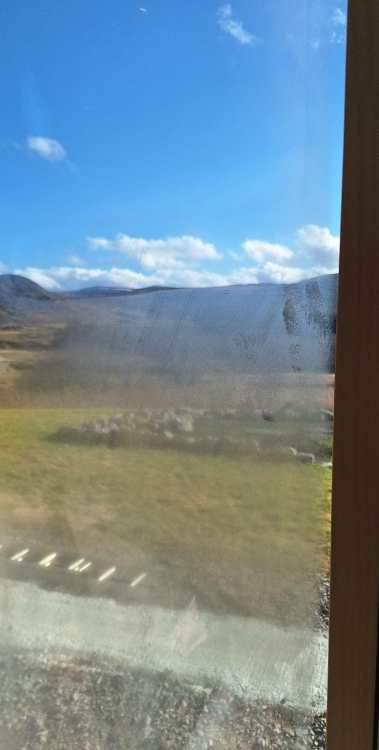
Bright sunny day today (for the first time in a while) and noticed what seems to be condensation or contamination between the panes. It's not on either touchable surface; it appears to be between the glass panes. Seems to be only in the large fixed pane which is ~2x2m; the opening pane beside it is fine. South facing if that makes any difference. Triple glazed, aluminium clad, installed 2025. Any ideas what this is? Causes? Solutions?
-
Ah, this is not OpenReach. It is a local area network broadband provider (coz we only haz copper BT cables in these backwards parts). But point taken - ask the service provider what they require.