Jeremy Harris
-
Posts
26430 -
Joined
-
Last visited
-
Days Won
360
Everything posted by Jeremy Harris
-
I could post you a lump of it easily enough. I've got a few bits sat in a box here from the big icicle of the stuff that formed down the rear of the case.
-
The thermistor string is in a dip tube that is sealed at the lower end and comes through a gland in the lid.
-
I did have an inline heater, but it was quite limited, so wouldn't run the shower. A tank that I can heat up when needed and provides the same flow rate as the Sunamp would just make for an easier to use back up I think. The one I've been looking at can supply about 117 litres of water at a mixed down 40°C and is actually cheaper than buying an inline unit, plus it only has a 2kW heating element, so can just be changeover switched from the Eddi supply, which is nice and easy to do.
-
That thought in your last sentence ran through my head earlier, looking at those photo's that @Nickfromwales posted. Looked to me almost like the beginnings of a DIY kit! I don't think that much PCM actually leaked from our unit, perhaps only 3 or 4% at most.
-
The supply and fit price looks exhorbitant to me. Before Sunamp agreed to replace the failed unit I looked around and found that I could buy the 9kWh/210 litre unit for £2,035.60, including VAT. Add on another £82.63 inc. VAT for the PV02 key, plus shipping at another £75 and the total comes to £2,193.23. The guys arrived to install the replacement unit just before 15:00 yesterday afternoon. The delivery guy was off and away with the old unit by 15:25. The new unit was in and switched on just after 16:00. The installer finished up and left at 16:35, so all told a couple of people for half an hour and one on his own for another hour and ten minutes. Clearly there was travel time, cost of vans, equipment, other overheads etc on top of these guys pay, but I'm struggling to see how that could add up to the silly price I was quoted. I could have hired a stair climber from the local hire place for £235/day, including delivery and collection by them. I'd happily pay someone's day rate for a job that took under two hours, given they might have travelling time etc. The most expensive trade I've used recently (chap that serviced and certified our treatment plant) charges £600 a day, including 50 miles travel, waste disposal etc. Someone should be able to swap over a duff Sunamp for a replacement for no more than £600 to £800 in labour, unless I'm seriously out of touch with prices. The total price should have been under £3k in total, rather than double that, IMHO. On a separate point, this experience of not having hot water has caused me to think about a back up system. Doesn't need to be super capable or anything, just needs to supply 120 to 150 litres at a mixed down 40°C (the "MAX40" number I think), so we could have a couple of quick showers. I've no floor space at all, but there is space up on one wall, I've got a space about 500mm wide and 1.4m high on a wall I could use, with a maximum projection off the wall of about 500mm or so. I've spotted a cheap wall-hung UVC that looks like it would fit in the space. The idea would be to plumb it to the hot and cold supplies on the wall beneath, with an easy to access isolator on the cold feed, plus a DP changeover switch to allow either the Sunamp or the UVC immersion to be heated. I'd need to add another 22mm discharge from the tundish, out through the wall and down to ground level, but that looks doable. I now know a keen local plumber, too, who wants to come over and talk about the Sunamp, so could get him to install the pipework and sign it off. Looking at the weight I'm sure I could get it up on the wall, ready to plumb in, easily enough, as there is already a big lifting eye by the ceiling right where it needs to go from when I lifted the old thermal store into place, years ago. My gut feeling is that for not too much money it would be useful to have a standby hot water system, even if it only has a modest capacity. Even a 3 or 4 minute hot shower would be a heck of a lot better than no shower!
-
They must have to leave a gap at the top for expansion, I'm sure, but they could do that if the cell was filled via a port, after assembly, which is what makes me think that they might need a very large opening in order to safely pour the molten PCM into the thing.
-
A stop hole. They do the same with cracks in aircraft structures . . .
-
Might there be a risk of the PCM getting overheated during the welding process? From what I remember from discussions around the time when the Sunamp first came out, the PCM was said to breakdown at a fairly low temperature, something like 120°C to 130°C sticks in my mind for some reason. I'd imagine that there would be a significant risk that the PCM towards the top might get to that sort of temperature whilst TIG/MIG welding a stainless cell closed. If I've understood Nick's description correctly, they fill the lower half of the cell up with hot (so liquid) PCM, then they add the lid and weld the two parts together. I'm guessing that they must have a good reason for doing it this way, perhaps relating to the viscosity of the molten PCM, rather than pouring the PCM in through a filling hole. Before I read Nick's description I'd assumed that they filled the cell up via the red cap, but it seems that is just a vent. It might also be made in two parts so the heat exchanger(s) can be fitted. Looks like this a secured to the upper section before the two parts are welded up. Presumably the top and heat exchanger(s) assembly is lowered into the still molten PCM, before it cools and sets solid around the thing. I can't see this being the only reason for welding the cell up after the heat exchanger(s) have been fitted, though. If the PCM could be poured in through a port of some kind then it makes sense to do the welding of the two halves before pouring the PCM in, if only because then all the welding can be done on horizontal surfaces, by putting the cell on its side and rotating it as it's welded. It seems so obvious to use a fully sealed container and just fill through some sort of fill port that I can only assume they must have a very good reason not to do it this way.
-
You might be right. My memory is from a structures course at RAE Farnborough in the 1980s, where we were shown a cine film of the Comet fuselage being pressure cycled in a big water tank, until the corner of one of the windows catastrophically failed, blowing out a fair chunk of the fuselage structure. It was a pretty dramatic bit of structural testing, the sort of thing that seemed to be commonplace back then, probably because doing manual stress calcs was such a laborious process, one that was very hard to apply to every element of every structure in any sort of fine detail.
-
If failure around the weld is the cause (and right now it's right up at the top of the list in terms of the reason for our unit failing) then that isn't a hard thing to fix during production. There have been quite a few failures involving leaking PCM, particularly from older units, and, given that Sunamp have improved the design a fair bit over the years it seems probable that they have looked at improving this aspect, especially if it was costing them a lot of money in warranty returns. May well be that improvements need more than just one change. Could be that they've improved the weld process as much as possible, but have also made other changes to reduce the stresses, like that deliberate ramp of power on start up. I know the old unit we had didn't do this, as I remember hearing the contactor clacking in and out as it pulsed power the elements during the first 20 minutes or so. Making that a linear ramp up will have added cost, so must have been done for a good reason. The emphasis on careful delivery and handling from manufacture to installation seems to be another change that may have been done for good reason. The setup the installer had yesterday, where the delivery van and lift crew were organised to arrive ten minutes before the installer, so the new unit could be upstairs ready to install and the old unit taken away as soon as it was out, looked to me to have been a process these guys used all the time, and it had a very clear focus on handling the thing very carefully. The installer even made a point of checking the packaging carefully for any sign of damage. Goodness knows what he'd have made of the state our old one arrived here in! Fingers crossed that the various improvements made over the past 6 years or so have made these units more reliable.
-
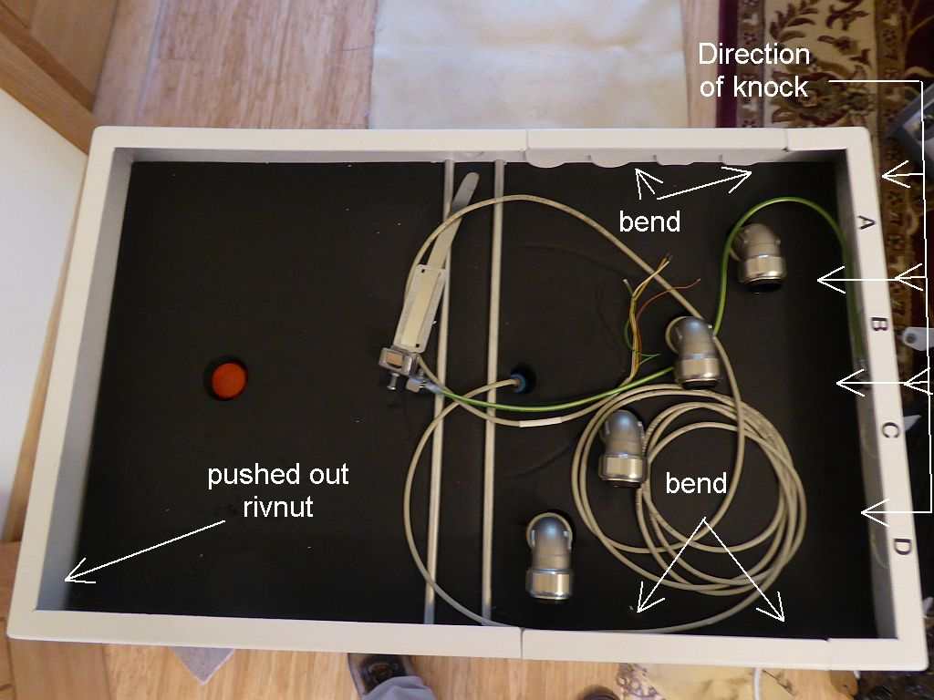
Very many thanks for that gem of information, Nick. It ties in very well with what I now think most probably happened to our unit. If this welded joint had been stressed by transit damage then it seems possible, perhaps even likely, that the cell in our old unit was just waiting to fail. It also ties in with the installer mentioning that some failures were down to transit damage. Our's had suffered a hefty knock near the top on the side where the pipes connect, which coincidentally seems to be where I think the leak may have been. From what little I could see of the top of our old unit it looked similar. Different elbows for the pipes but the rest looks the same. I suspect there may have been several different iterations of the design, some driven by value engineering, perhaps some driven by the findings from product failures. Seems quite likely that the weld process along that seam could be one such potential failure point, perhaps exacerbated by transit damage. Easy to see how a knock might start a crack, that then gradually grows over the years until the point where the PCM leaks out. Just found this photo that I remember sending to Sunamp when I found the transit damage back in 2018. I've added some annotations to it. The leak seemed to be around that end to the right where the knock seems to have been. That knock was enough to cause the lid to move left and rip out the rivnut at the lower left corner. Seems possible that this could have caused hidden damage to the weld. The plates where the pipe holes are were both bent inwards, presumably by the force applied to the right hand top of the unit when it fell over in transit (and I strongly suspect from the pallet damage and marks on the cardboard that it may have fallen over).

-
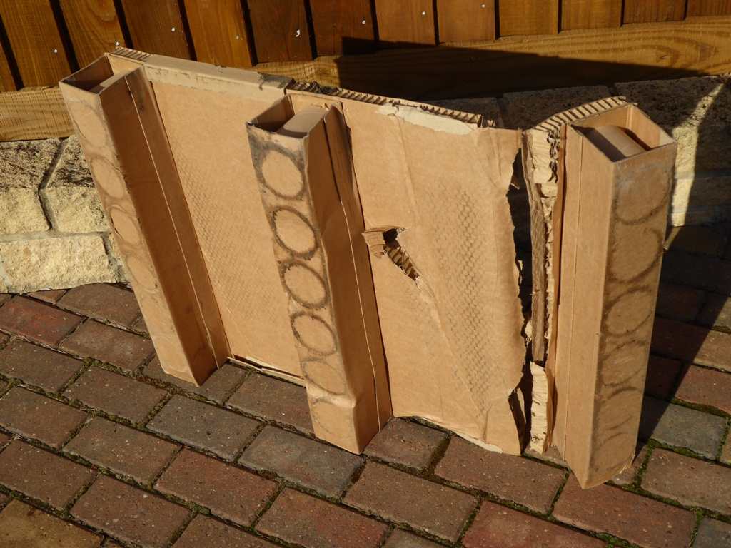
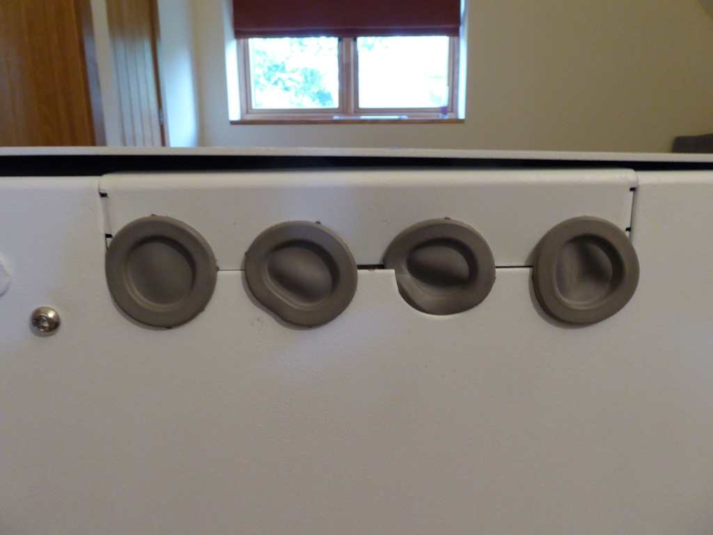
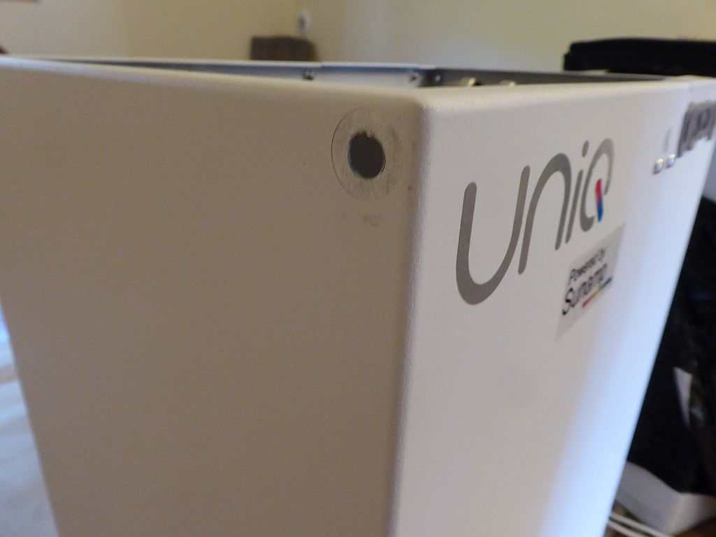
I believe that the design has probably changed quite a lot, and I have a strong suspicion that the heating element is something very different to the original immersion heater design, because of that slow ramp up in power on cold start. There's no power modulation in the control box, it seems to use a relay to turn the power on and off to the heating element. In our old UniQ that relay directly switched power to immersion heating elements in the base. This is what the start up power looked like, from first cold start, showing the ramp (the dip is where we turned the bypass switch off on the Eddi and switched to the one hour boost, so the power was off for a short time): This wasn't anything to do with the Eddi, as the first part of that ramp was with the Eddi off (the bypass switch was on) and the second part is with the Eddi on, in boost mode. This means there must be some sort of heating element control going on outwith the stuff in the control box itself (because that clearly only turns the supply on and off to the heater). There has to be a good reason for Sunamp having made this change, I'm sure. I don't think that it's a coincidence that some early models, with a resettable thermal trip next to the heating elements in the base (our old one had this) had some issues with that trip operating and turning the unit off. When the contactor in the control box failed on our first unit the advice from Sunamp was to check and reset that trip (which hadn't operated, the contactor had just mechanically broken internally). As for a vent, then I believe that the filling plug may do double duty as an over-pressure vent, although I can't be sure. It was fine on our old unit, the leak seemed to be at the other end somewhere. This again makes me think that the cause of our leak may just have been a failure in the casing somewhere, perhaps a latent manufacturing defect or even (as was mentioned by the installer) possible transit damage. Our unit did have a very rough ride during delivery. I reported this to Sunamp, with photos, at the time, as the pallet had been broken by a forklift and the unit may well have fallen over, as there was damage to the top of the casing, where the pipe entry cut outs are, plus the lid was damaged with a force so great that one of the lid securing screw rivnuts was ripped out (I fitted a new rivnut to fix this). These were the damage photos taken at the time, with the wrecked pallet it arrived on, the dented case and the ripped out rivnut hole: At the time, Sunamp didn't believe that there had been internal damage, but in the light of what the installer said yesterday about the care they now take when transporting and lifting units into place it has made me wonder whether or not there may have been some slight damage internally that has taken years to turn into a leak. The more I think about it the more believable I think this scenario may be. The sheer weight of these things does mean that if one was to fall over during delivery then it seems quite possible that this might cause internal damage. I think it's quite possible that some of the other cases of failure may be related to possible transit damage, thinking about it. It ties in with the way they are now delivered, if my experience yesterday is typical, where a great deal of care is taken to transport these things carefully, at every stage of their journey. My original UniQ unit arrived via a standard pallet service, and had clearly been subject to some fairly rough treatment along the way. Just to get it off the truck was a challenge, and with the damage to the pallet I had to transfer it to a spare timber pallet at the truck in order to be able to get it to our front door. I seem to remember Sunamp saying they were going to speak with the transport company and look at using more robust pallets at the time. Is it a coincidence that the end of my old unit that got a knock is the same end as the leak has appeared?


-
It could well be something like that, or just something relating to the manufacture of the casings, perhaps. As de Havilland tragically found out in the 1950's, squar'ish shapes do not tolerate fatigue cycling anywhere near as well as round'ish shapes. The stresses in corners are always a lot greater than in the same material under the same forces that doesn't have corners. It took loads of testing in a massive water tank at Farnborough to discover why the early Comets were breaking up in flight, as no one had considered the impact of stress concentrations at the corners of rectangular openings in the pressure hull.
-
@Nickfromwales, Out of curiosity I had a good look at the sensor string in our failed unit, to see if it had moved. Easy to determine that it hadn't, as there's no form of gland at the top of the dip tube on our old unit and the cable was folded over where it had been under the insulation, so would have been physically restrained from moving upwards. I pulled the sensor string out to check, and it looked undamaged, same as when it went in from what I can remember. I also had a look to see if there was somewhere obvious that the PCM had leaked from but couldn't see anything. The filling plug (which I had thought might be a blow-off point) looked fine, in fact the area at that end of the cell looked pretty dry, as did the pipe entry points into the top of the cell. If I had to guess, based on the fact that the PCM had pushed up around the edges and leaked out around the pipe entry points (but not obviously out of the cover over the heating element terminals) my suspicion would be that the casing might have cracked, perhaps somewhere close to the top corner, at the pipe entry end somewhere. The PCM looked to have pushed up between the cell case side and the VIP panels in that area. Doesn't really make anything any clearer, I'm afraid. All that seems fairly certain is that this failure wasn't caused by anything on the water side, there was zero evidence of any water leakage at all, so I suspect the concerns I expressed earlier about some sort of over-pressure event almost certainly had nothing at all to do with it. Very annoying not being able to understand the exact cause of the failure, both because I'm too damned curious for my own good, and always want to know WHY stuff happens, but also because it'd be reassuring to better understand these things, perhaps even to find ways to reduce the risk of it happening again. Guess I'll just have to accept that it is what it is.
-
The one they used didn't have tracks, but motorised wheels and moving step things that grabbed each stair and lifted the wheels up the next step. It also had a motorised lift platform, which made getting the heavy box out of the back of a van easy, it's a bit like a mini-forklift. It definitely wouldn't go up a ladder though, I'm afraid!
-
None at all. He checked the pressure regulating valve, checked the 100 litre accumulator sat almost next to the the thing and checked the incoming pressure from the well pump and, quite sensibly, concluded that there was zero risk of the supply going over the upper pressure limit. He did also say that he'd never seen a failure caused by supply over-pressure, he reckoned leaks were most often down to poor workmanship during installation. He reckoned most failures were electrical or poor installation workmanship, with a strong view that the latter was the cause of a fair few. PCM leaks weren't high on the list of things that happen, especially with the newer models, according to his view. The pipe work has been simplified on the new unit, too. It doesn't have two sets of heat exchanger pipes, just one set, which makes installation a bit simpler for electric-only installations, like ours. Most impressive takeaway from today was just how awesome the Zonzini stair climber was. Instead of me sweating away for hours with a sack truck, ropes and a tirfor winch to get the thing upstairs, the motorised Zonzoni just drove straight in the door and up the stairs in a couple of minutes! Having seen it working I'd no hesitate to just hire one if I ever needed to move anything hefty. I reckon I could have very easily got a new unit in and the old unit out using one of these, and really it's the heavy lifting that is the hardest part of the job, the rest is pretty straightforward.
-
Yes, I've already sorted how to do this. The Sunamp sits on top of a bit of 19mm varnished marine ply. I've sealed along the back with a bit of Sikaflexed plastic angle to the panelling behind. The plan is to add three sides to the edges of the ply to form a bund to limit the flow of anything that may leak (although I sincerely hope it doesn't!).
-
To be fair, I didn't ask them to fix the damage. The flooring damage is a ten minute job, as I have a part-box of left-over carpet tiles I can use. The plasterer was around earlier and having had a good look can't see any damage or reason to pull the ceiling down and replace it, so I'm just going to make good the surface and try repainting it, perhaps with a coat of some sort of stopper/sealer first. It's not a large area, so not worth getting a decorator in. I can't see any build up of crystalline PCM in the ceiling void, it looks almost as if the felt of the carpet tiles has worked as a sort of crude filter to leave most of the crystals behind.
-
All prepared! I managed to quickly Sikaflex a bit of plastic angle along the rear, to seal the bit I wouldn't be able to get at, and got the installer to fit the new unit slightly further out. All I need to do now is add the other three sides, the plan is to just bond and screw some boards around the edges of the bit of varnished marine ply that the unit is sat on. I'm pretty sure this will catch any PCM leak, should I be unlucky enough to experience another one. I'm also going to seal up that hole in the floor, when I replace the damaged carpet tiles around the unit (I still have a load of spares left over from fitting them, it's good to hoard stuff sometimes!). Sunamp have definitely made some significant changes to the way their control system works. The original unit I had just went through an initial commissioning stage on first power on where it clacked the contactor on and off repeatedly for around 20 minutes. This new one smoothly modulated the power at a rate of increase of around 150W per minute during that initial stage. No doubt this is a fair bit more benign in terms of the way the PCM initially melts around the element. I can't really fault Sunamp, unless I was being really picky. They agreed to change the unit on Tuesday and by just after 16:00 on Thursday the job was completed. That's pretty good service in my view.
-
Out of the blue I had a phone call just after lunch from the installer, who was on his way to us, about 2 hours away. Two vans arrived just before 15:00, one with the lifting crew and a stock of Sunamps, the other with the plumber. Within ten minutes the new Sunamp was up the stairs and ready to install, ten minutes later the old one was out, loaded in the delivery guys van and they were off. The new unit has been in for about half an hour or so and is now charging, the installer's happy all's well and has just left. Total time from the first van arriving to last van leaving was 1 hour 40 minutes, so not a difficult job. Does make me wonder how the chap from Bristol had the brass neck to want several thousands pounds labour for a job that took less than two hours . . . Anyway, hats off to Sunamp, I really can't fault the speed with which they've fixed this. Impressed by both the handling crew who did the delivery and lifting and by the installer. Poor lad had driven all the way down from Nuneaton to do this job.
-
Very easy to miss, Nick, if it wasn't for the fact that I'd used this exact PCB fuse before, back when I built the first iteration of our house environmental monitoring system (the very old Picaxe microcontroller based one) then I'd have missed it, too, TBH. I wasn't actually looking for it, either. I just wanted to compare the board inside our box with the one in your photo's, just out of curiosity, to see what had changed (not very much, it seems)!
-
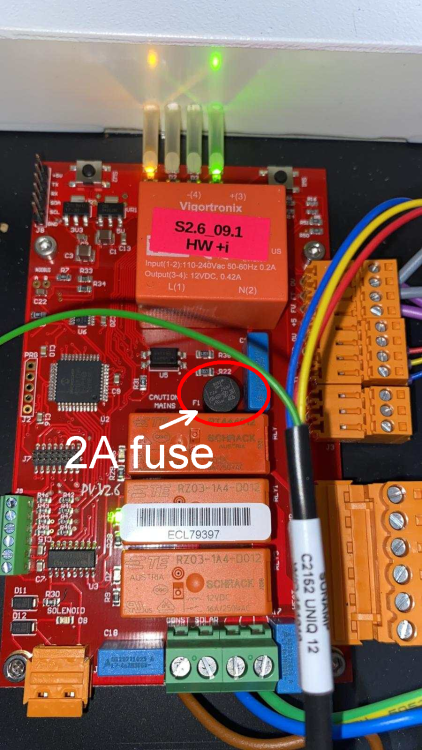
I've had a look inside our UniQ control box and it does have a 2A fuse on the incoming supply to the PCB, as does the board in your photo, @Nickfromwales. Not obvious unless you know what these Buss PCB fuses look like though. From one of your photos, it's marked "F1" on the board screen print: This would be fine for back-protecting up to a 3m 0.75mm² cable run, even though it's perhaps not ideal, in that it's generally best to protect cables at the supply end. It would prevent the PCB tracks from blowing though, I'm sure, and is probably good enough to protect the cable in the majority of installations, perhaps.
-
That's two versions later than the last PDF I had. The version I had (just after I had installed the thing) was V2.0. I think the one I worked to initially may have been V1.7, maybe V1.8, can't be 100% sure as I made a point of deleting all the earlier drafts in case I opened the wrong one by mistake!
-
I, too, haven't been here for a long time, I needed a break after the build and just had to get away from self-build related talk for a time, as it was gradually doing my head in (as well as absorbing a great deal of time). I admire your enthusiasm, though! There is no way I'm ever going to even think about another project, even though I still keep thinking of things I'd do differently if doing it again.
-
Interesting that, as the first copy of the UniQ MIs I have don't mention the fuse for the always-on supply, but the second version sort of does (right at the very end)! Mind you, the documents I had for the UniQ were pretty much all drafts, I believe, rather than the final version that accompanied the product. Given it was such a simple thing to install I never really gave it much thought, TBH, especially as I'd spent a fair bit of time on the phone with their (very helpful) technical chap, discussing the installation.