Nelliekins
-
Posts
157 -
Joined
-
Last visited
-
Days Won
3
Everything posted by Nelliekins
-
Lancashire. The box section projects into cantilever so we can just screw the tread to the riser in an L shape and attach to the box section from underneath. But sleepers could still be sliced down if they're at least 235mm wide / deep. Screwed through the box section steel from underneath. Yep. Scientists have a word for it... Heavy. ? The PFC weighs 23.6kg per linear metre (because it was mislabelled as 180x75 when it was 180x90), with just over 11m in total. The box section weighs too little to care about - perhaps 35kg all in. Inclusive of the timber we are looking at about 350kg including the timber. Next time we will use 120x65 PFC instead of this absurdity! But at least this won't bend or bounce!
-
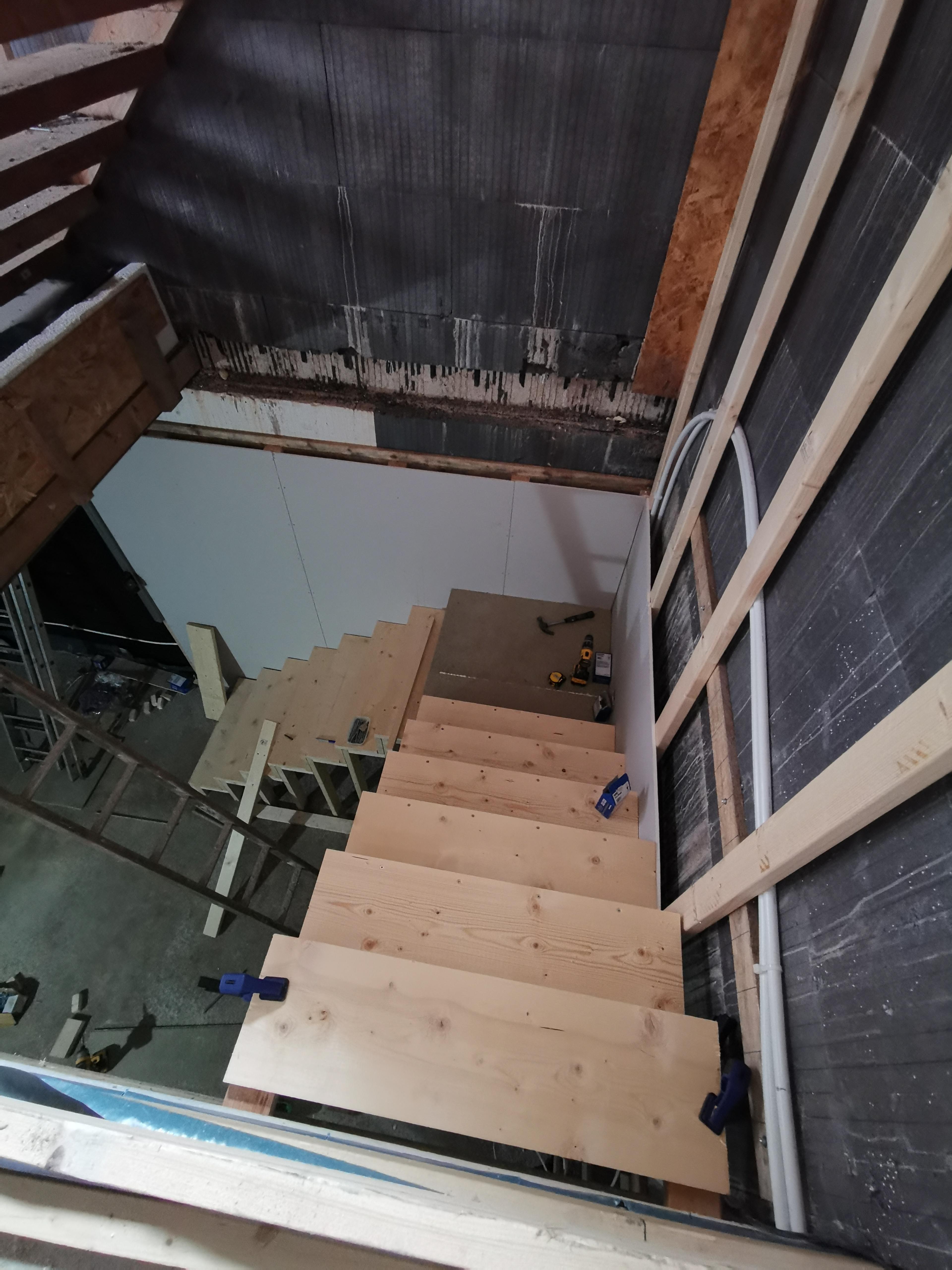
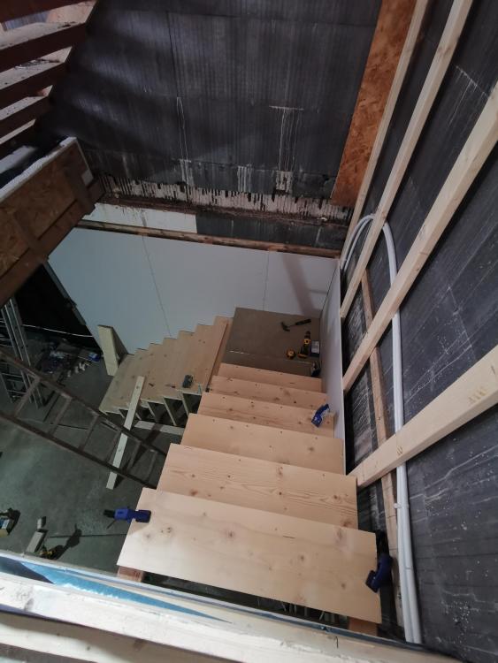
All being well it'll have a steel framed handrail welded on tomorrow, and nobody on site before that part gets underway anyway! The uprights for the handrail were cut this afternoon, and both the 4x2 timber and the plasterboard are in the garage ready to attach to it. We even have a variety of tek bolt lengths to get the best fit without sharp bits sticking through anywhere! ? The treads are proving more of a challenge, actually. The basement stairs are just spruce planks chopped down to 900mm wide. I thought of doing the same here but since we have a load of oak doors going in am wondering if we shouldn't get a better match for them... Anyone know where to get cheap oak planks from? Looking for a big pile (30!) of 900x240x38 treads and 900x185x38 risers to match... For now I am going to saw through a set of scales planks I have lying around - the treads will be a bit short but they will easily carry over the 620mm span at least, and they only cost a tenner each!
-
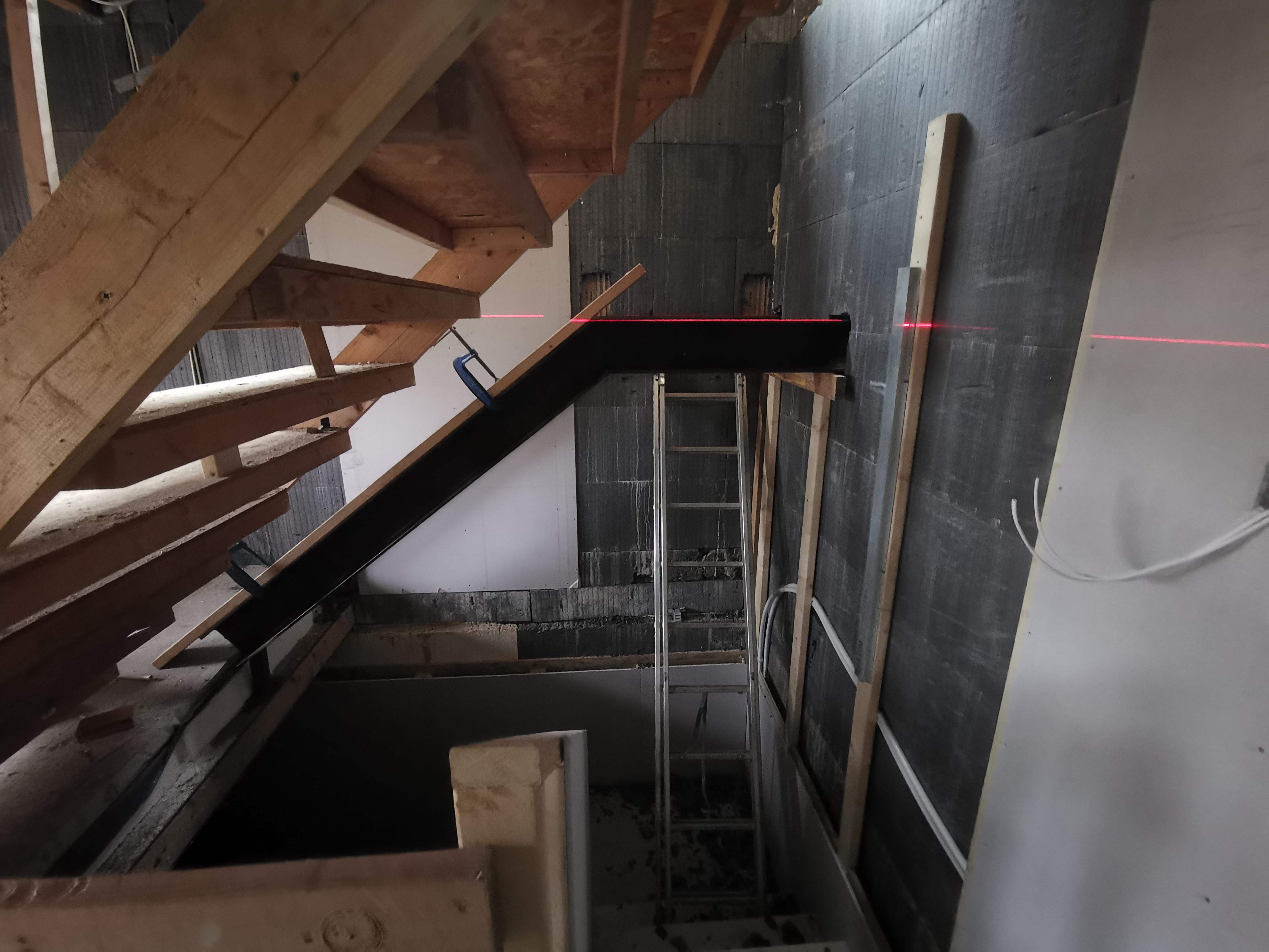
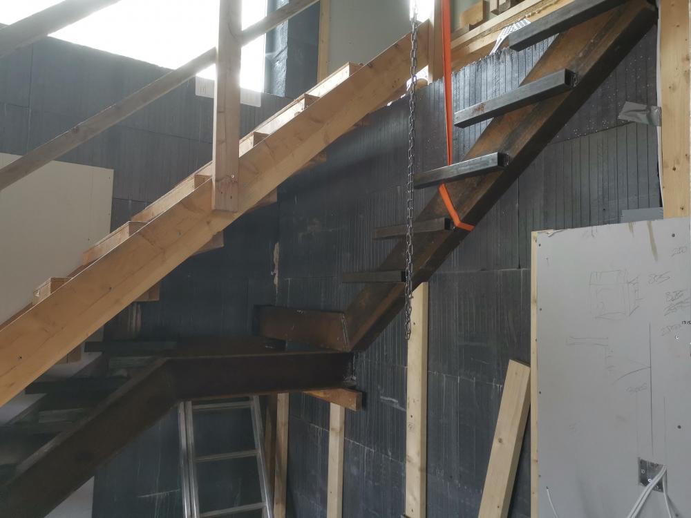
Ok so another visit from my welding friend, and we still aren't finished... ? Making progress at least : The old temporary status have been dismantled and the tread supports are now welded on fully. The "square" section for the landing is warped though - the top flight is 900mm apart from the top to the crank point, and then is 15mm too narrow where it goes into the wall. Rather than try to straighten the cranked beams, we are just going to pack off the face before the last riser. Next up is the handrail - we are going to place 1.5m lengths of 50mm box section welded to the side of the cranked beams on the right hand side (going up). 5 lengths, spaced at around 1 apart, should be good enough to attach a timber and plasterboard wall to...
-
As an aside, I just noticed that although the PFC is marked as 180x75 its actually 180x90. Wondered why it was so damned heavy lifting into place! Next time I think I will use something lighter like 125x65, because this stuff is insanely strong / rigid and is massive overkill!
-
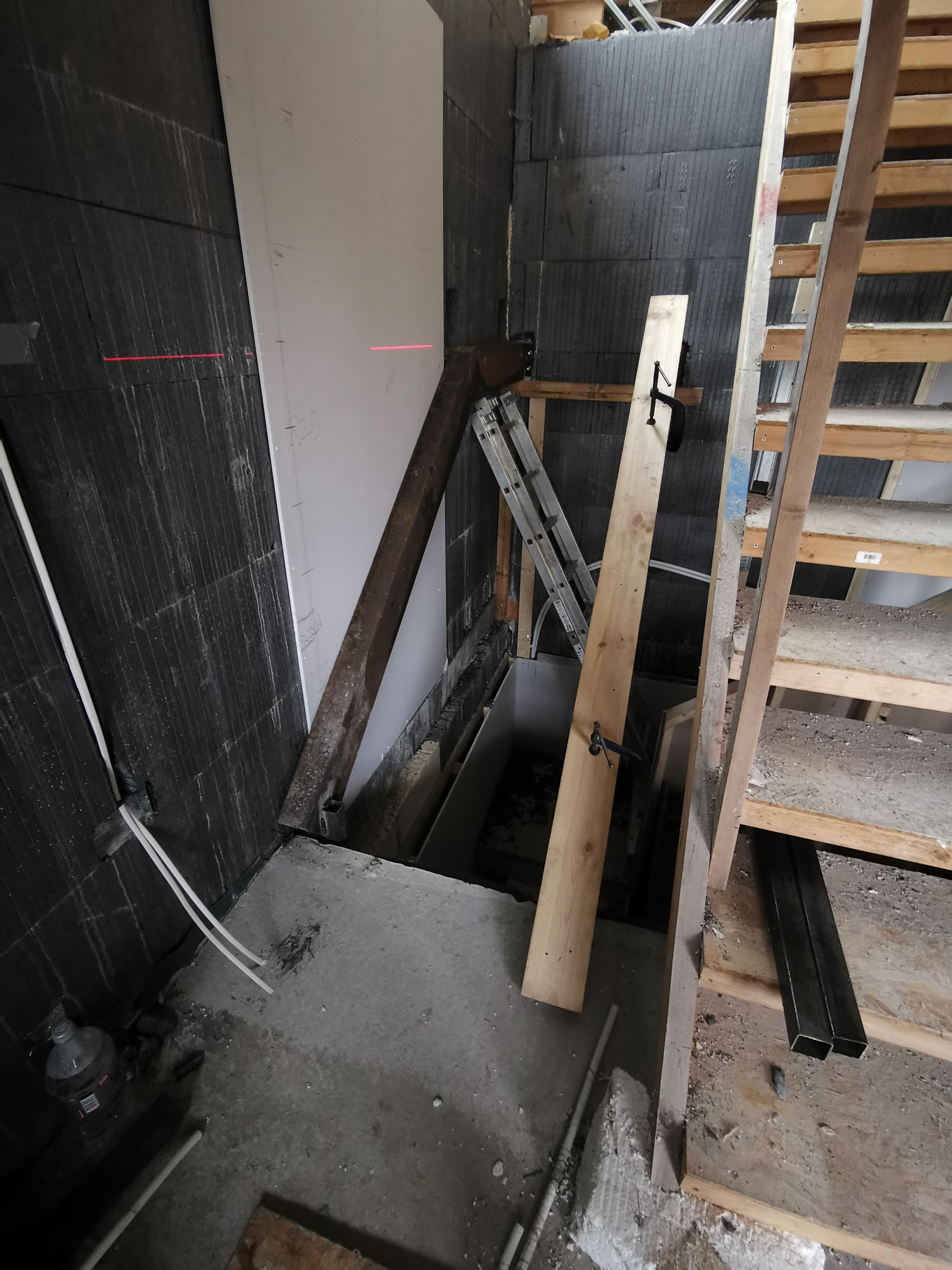
OK so it didn't go quite to plan... Bottom flight seems perfect - exactly 190mm rise on each tread of 240mm (although the treads aren't fitted yet). However the top flight has gone completely wrong. First, it transpires that using a spacer between treads when welding only works if it doesn't react to temperature... I used a piece of 140x38 CLS timber, having measured it first to confirm the size. However after getting warm through proximity to a welded joint, it distorted to 138mm on one side and 141mm on the other... But I didn't notice. Second, spacers are all well and good, but when the steel you're welding isn't actually the expected dimensions, you end up with an incremental error. Our 50mm box section came in 2 lengths - one was cut for the bottom flight and was nigh on perfect. The other was cut for the top flight, and according to a friend's caliper is 51.6mm. Doesn't sound a lot does it? However, that and the warped timber amounts to an error of 15.6mm on the top of a 6-tread flight. That's a problem. What's worse, there's a 4mm difference in the floor-to-floor height between where I measured and where the stairs start (because there's no way to measure directly where the stairs start - you have to use a laser to transfer the mark). So that's made the top step approx 20mm too shallow on the rise. Here's where we are at now - partially dismantled upper flight, so that we can adjust all the box section bits and make it right. Can't even do it in situ because the EPS isn't safe around fire!
-
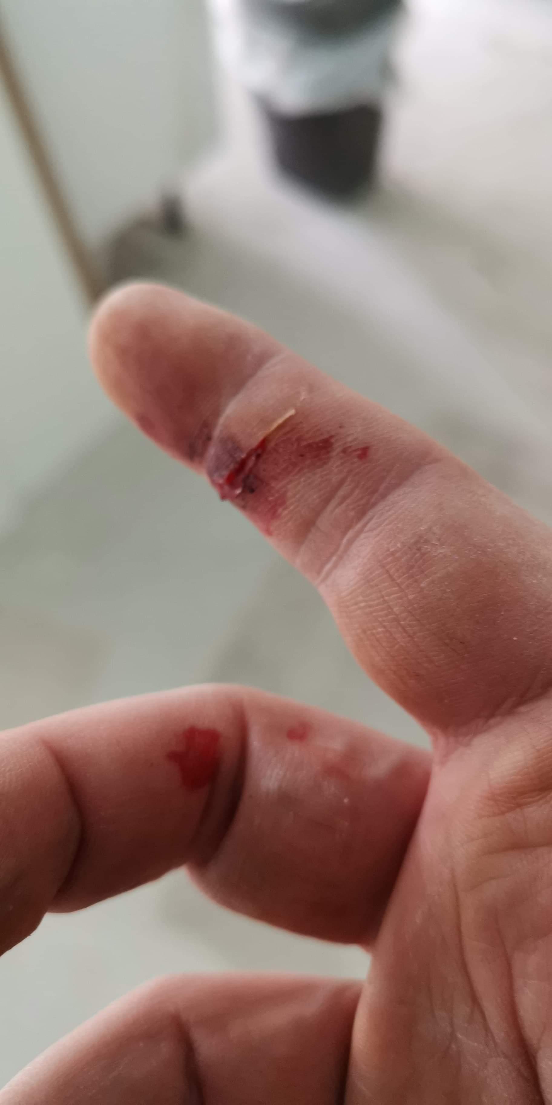
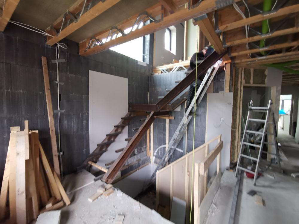
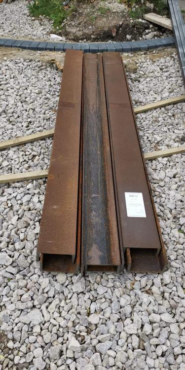
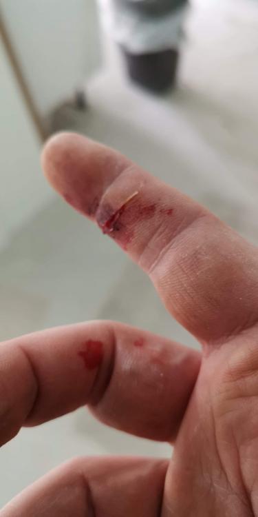
It starts!! Not much to look at, this steel stuff... Rusted to within an inch of its life! Despite this, all about as sharp as you could possibly imagine - nearly sliced my finger off picking the first one up! Still, some judicious use of gauze and tape and ready to carry on. My part-time builder came round to help me chop the steel, weld it all up, etc. After a day, we aren't as far through as I expected... That's one cranked beam, made from 180x75 PFC, and installed adjacent the wall. It's standing on a leg near-side which runs down to an I-beam in the floor, and some 120mm Thunderbolts bolted through a welded plate into the reinforced concrete wall at the far end. The timber is covering the second cranked beam, which has since been fixed in place in the same ways. Those 2 cranked beams will form the bottom flight of stairs, once the 50x50x3 box section is welded and/or tek-bolted to the PFCs for each tread. Here's the side view: On top of the landing part, we will be putting another pair of cranked beams (the same as these two but upside down) set at 90° (going up to the right) that will be welded onto a steel plate we have affixed to a double posi joist at the top of the stairwell. So far so good, but between the weather and the uneven ICF internal walls, it took 7 hours to get to this point... Let's hope tomorrow is more productive!


-
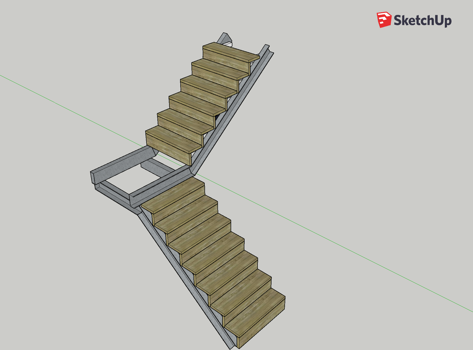
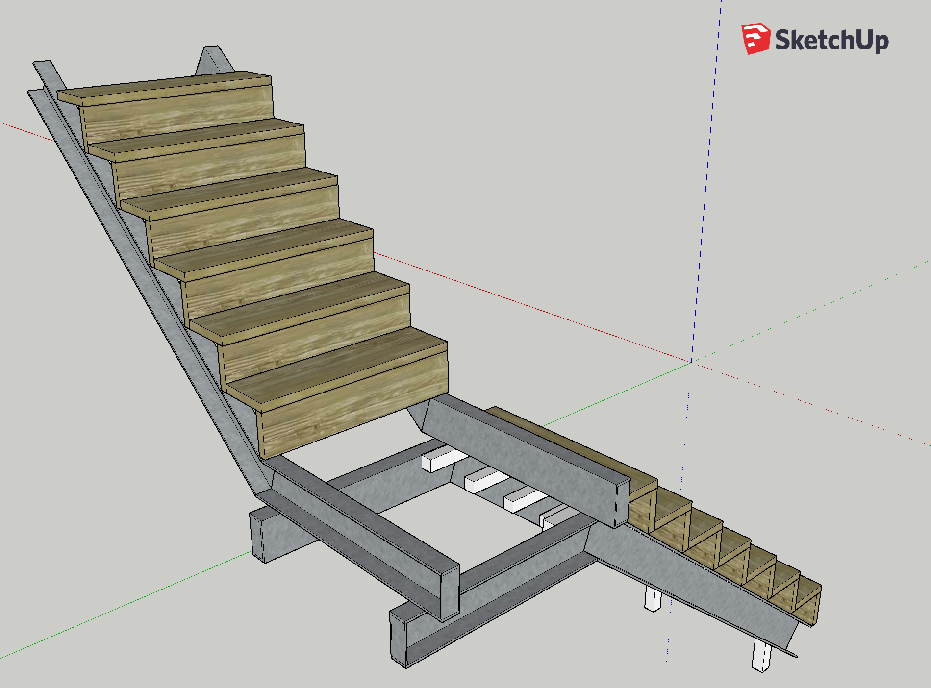
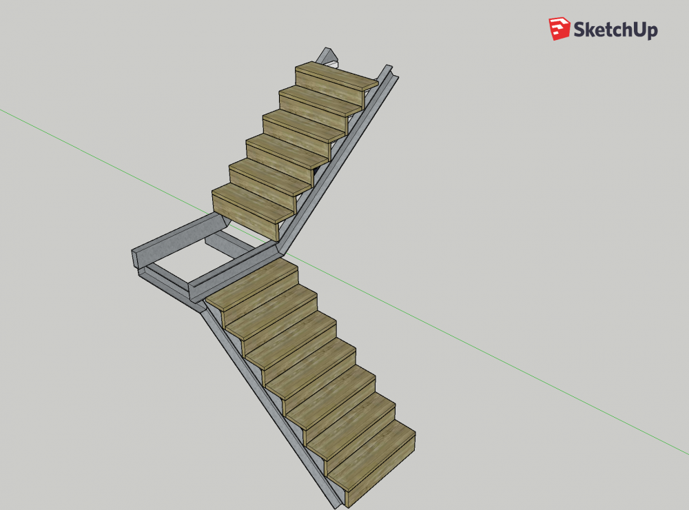
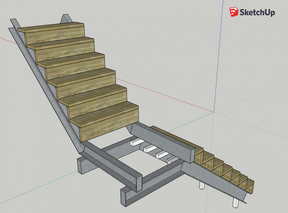
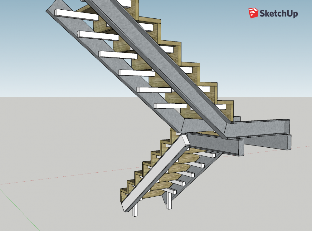
I think a simple set of deflection calcs could be knocked up without an engineer. I ended up checking a bunch of our first engineer's calcs because I was being told by Logix and NUDURA that he was being overly cautious... Anyway, here's an improvement on the design... The stringers are underslung PFC 180x75x20. The white box section is 50x50x3. The treads are sat on cantilevered box section welded to the PFC. The 2 stubby little legs at the bottom affix the base to a steel beam set into the basement ceiling, which was designed to carry the weight of these stairs and the concrete ground floor as well. Treads and risers are timber - spruce / redwood to start, oak or ash eventually. Total weight for the staircase will be around 450kg, but at least half of that is loaded onto our steel reinforced concrete walls. Oh and the beams will be tidied up at the ends, and the landing covered with timber on top of joists in hangers every 300mm. The handrail will be made from stud walls (4x2) bolted to timbers in the PFC webs, and braced at both ends by more handrail (it'll be continuous all the way through the 3 floors). Comments welcome!
-
Not really suitable for the space because the opening has been designed for a lift shaft to go down the "spare" area in the opening. Aye - we already have a double posi-joist at the top of the stairs. It's 2.85m floor-to-floor. The upstairs floor build-up is 255mm posi-joist, 22mm structural deck, 50mm EPS and 18mm floating floor, so 345mm total depth. Thanks - will check them out.
-
That's what we thought of first, but decided it wouldn't look great... Steel stairs would float which is (in our opinion) a much cleaner look, and wouldn't get in the way trying to get stuff down the stairs either!
-
Makes sense, and would probably be a lot cheaper too! Yep, something like 200mm lengths of 50x50x5 would be perfect I would think. We would bolt a timber to the steel plate if for no other reason than to match the treads and risers (which will be timber). And the treads and risers would give us racking strength as well. Plus a point to build a handrail from...
-
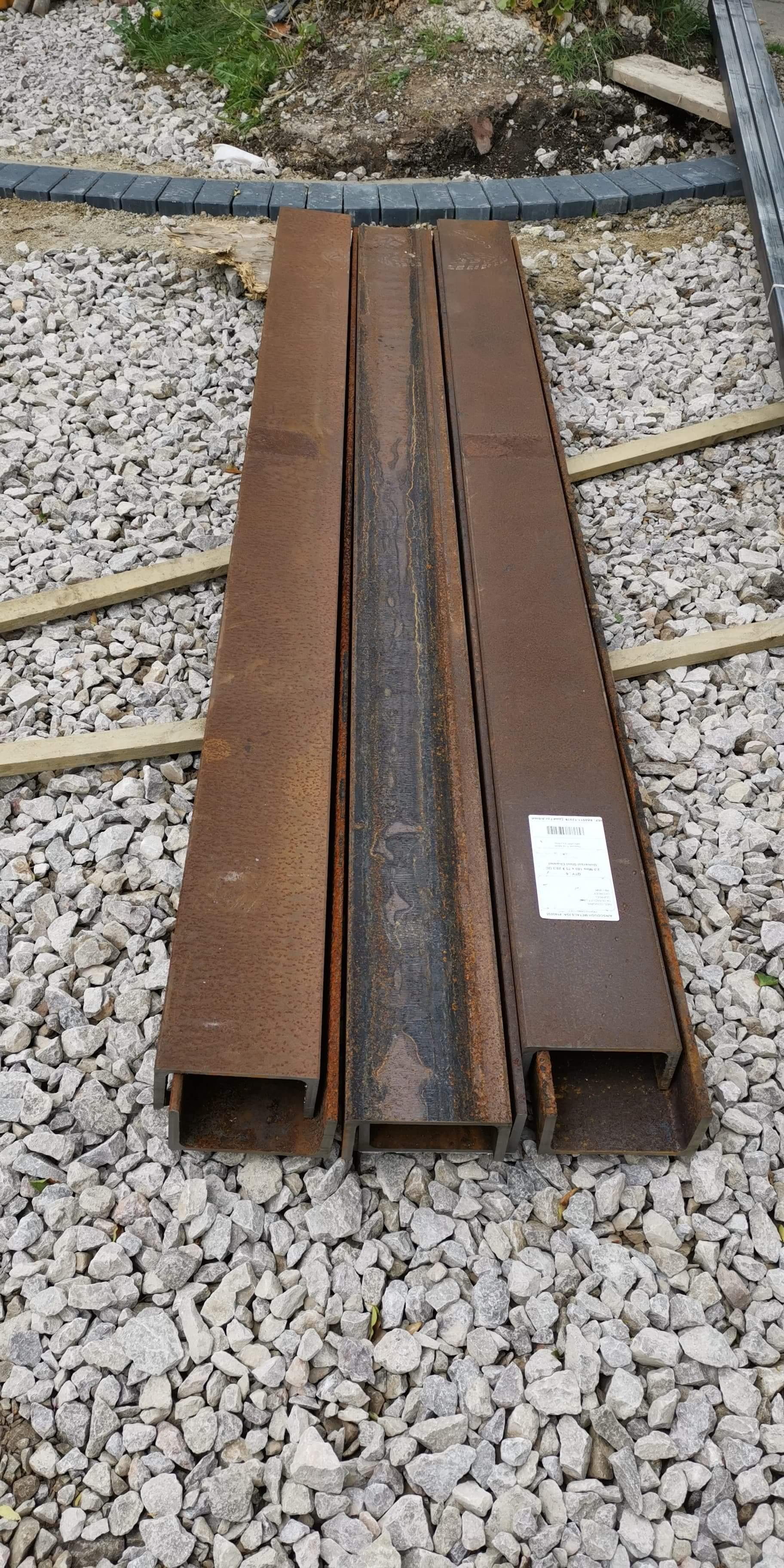
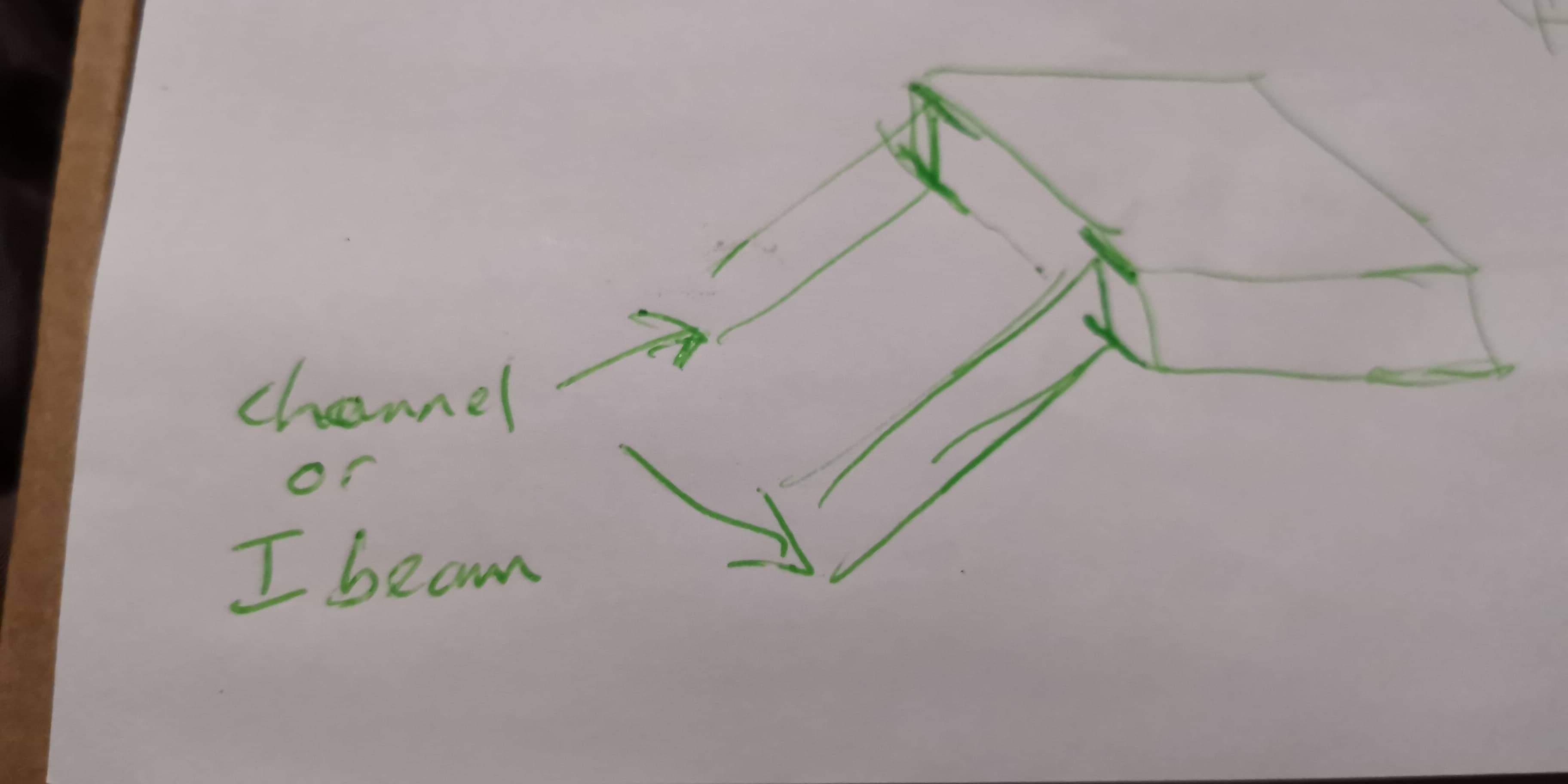
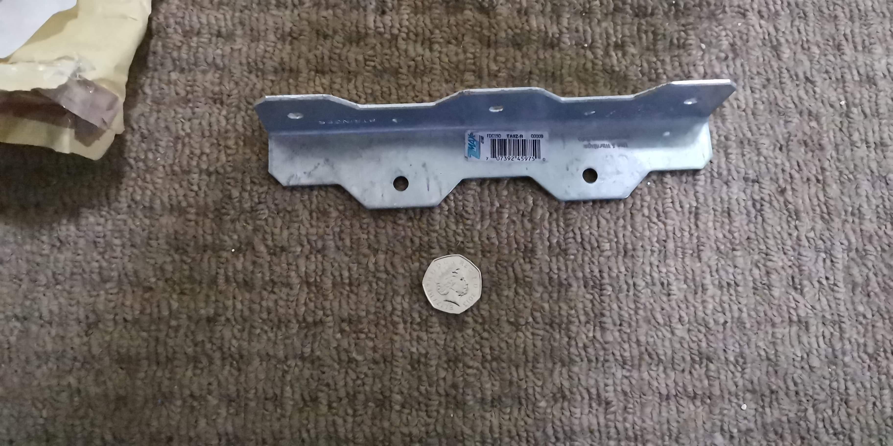
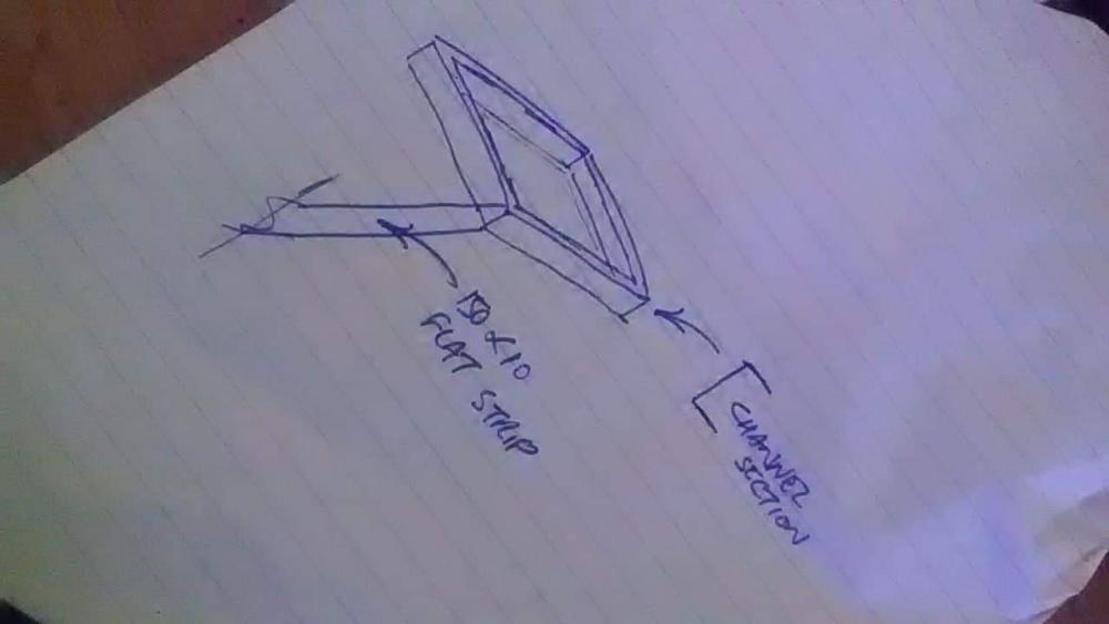
OK so we have blown the budget for the house, primarily fixing the leak in the basement that we got thanks to Logix UK... ? We need some stairs to go up from ground floor to first floor. We're looking at a quarter landing, with the landing outer edges against concrete ICF walls, so 3 corners of the landing can be fixed to concrete. However the inner corner of the quarter landing has no support. We can't put a newel post up from ground floor, because the stairs are directly over the stairwell to the basement. Here's a picture of the basement stairs: We need to mirror this staircase, directly above it. I can't think of a solution with timber, so I am thinking outside the box. Could we weld some steel channel as the stringers and a frame for the quarter landing, then steel angle on each stringer as a support for the treads? We have a tame welder who will work for scotch (after he's finished!) and the steel channel only costs 100 quid... Any thoughts anyone? This is the detail I am thinking of for lower flight to landing: Or maybe this : Then we would weld brackets like these for the treads to sit on : They're made by Simpson Strong Tie, and specifically designed for stair treads, and cost about a fiver. Suggestions welcome!


-
Heating system for an ICF house with UFH
Nelliekins replied to Nelliekins's topic in Other Heating Systems
Hmmm... That might work you know! Good idea! Just have to work out how to fit 2 into the same part of the return... ? -
Heating system for an ICF house with UFH
Nelliekins replied to Nelliekins's topic in Other Heating Systems
@PeterW I am beginning to wonder if the 2 port valve were the best idea... How will we circulate the water without taking in heat from the cylinder, e.g. to distribute solar gain from the kitchen? Am thinking that a 3 way diverter (not mid-position) valve would either connect a circuit to the flow from the coil or "short across" to the return. Thinking about it, we would need a 2 port valve as well as the 2no. 3-port valves, to close off the return that goes to the coil, correct? -
Short length of 51mm x 114mm oval?
Nelliekins replied to phatboy's topic in Mechanical Ventilation with Heat Recovery (MVHR)
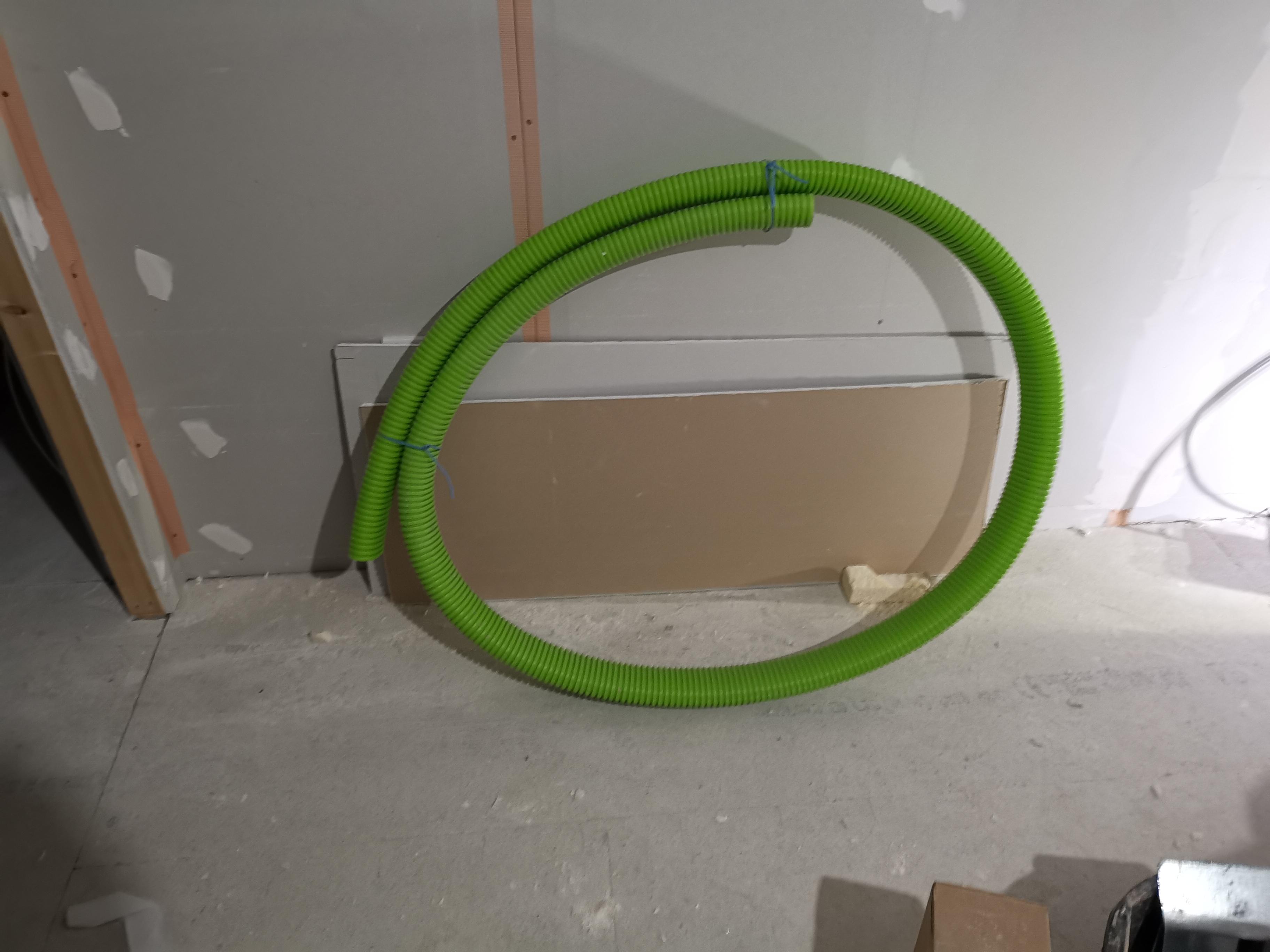
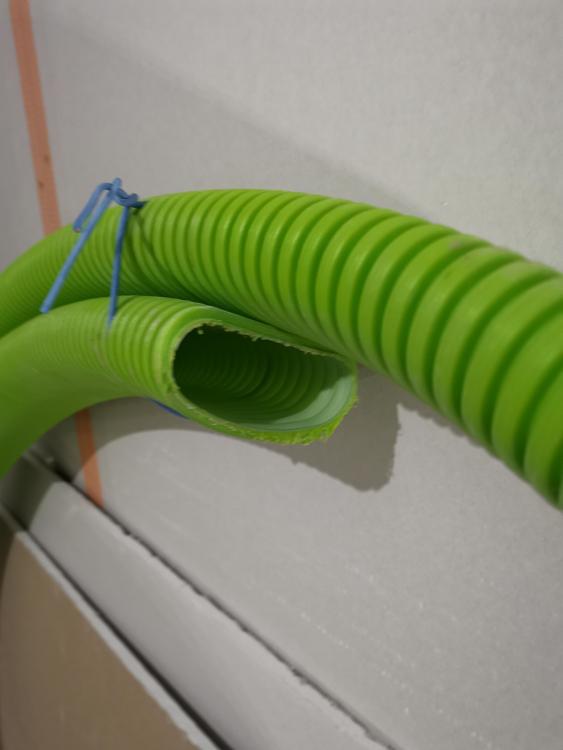
Hi Tim. We are in Chorley in Lancashire. Could probably get it to Bristol without too much effort... The ducting does fold over on itself without damaging, so might be able to get it in a 1m * 0.3m * 0.3m parcel... Want me to try and box it up? Neil. -
Heating system for an ICF house with UFH
Nelliekins replied to Nelliekins's topic in Other Heating Systems
It is indeed an ordinary indirect cylinder, 140L stainless steel RM Aquastel. Jeremy's spreadsheet said 25-26°C floor temp was what we were aiming for. Mixing valve is good for 25-50°C, and was set at 3/10. Flow was steady 20°C and return around 17°C. I boosted the cylinder temp from 55°C to 65°C by turning up the wick a bit on Mr Boiler, and then went to look at the mixing valve... I set it midway (5/10) at 5:30pm today. By 7pm, flow was up from 20°C to 28°C and return was 22°C on concrete floors and 26°C on 1st floor. So fiddling with the mixing valve and giving the boiler a bit more gas seems to have sorted the UFH temps... ? Still suspicious that it won't cut the mustard if it gets properly cold outside, but for now we have heating! -
Heating system for an ICF house with UFH
Nelliekins replied to Nelliekins's topic in Other Heating Systems
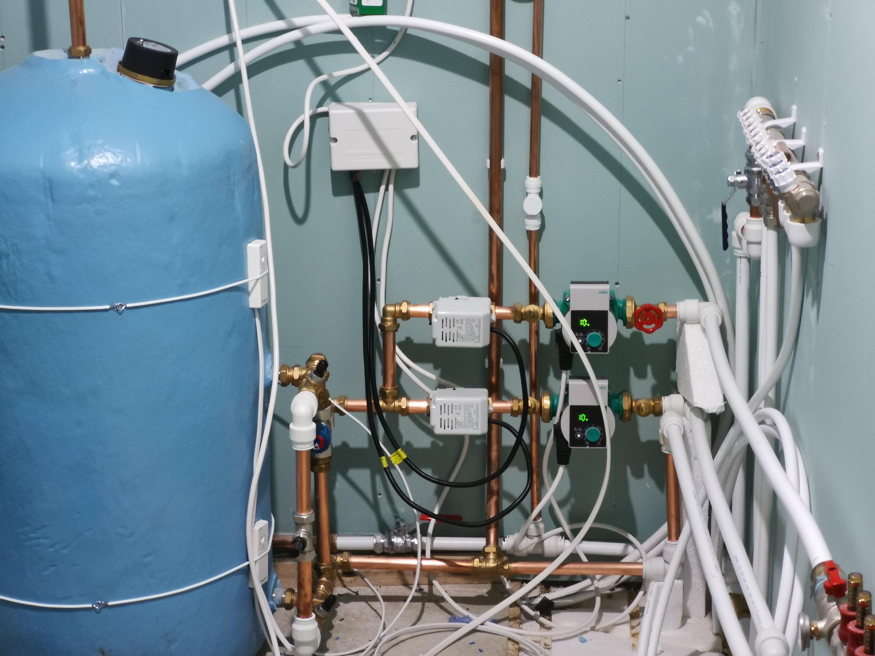
@PeterW ok I have fitted 2-port valves to each of the circuits, and pumps inline with each valve (driven by the valves). Here's a photo : (ignore the wiring and plumbing chaos - there's a rainwater distribution manifold and 2 wiring centres yet to fit!) So, what we have is coil going to tee on both flow and return. One loop formed by bypass valve set at 2 bar (little black thing by cylinder stat) . Other loop formed by Reliance mixing valve rated for 25-50C output, which then gets split to go into the circuits for UFH pumping. It all seems to work, except for one detail... After 30 minutes of running, the flow on the manifolds was 20C and return 12C. Fine, but after 24 hours of running the flow was still 20C with return up to around 17C. Clearly 20C isn't quite warm enough for the UFH - the spreadsheet from @JSHarris said 25C was the goal for our house. With one pump knocked off (thereby getting all the heat from the coil into just one half of the floor) it still stayed at 20C. My guess is that I have a few options: 1. Increase the cylinder temp from 55C to around 70C to see if that gets more heat into the coil 2. Impede the flow rate somehow so that the water travels through the coil slower (pumps already at minimum rate though!) 3. Replace the cylinder with one that has a more useful coil Have I missed anything? Going to put some DS18B20s into the thermowells all over the system tonight to see if I am missing anything simple...
-
Short length of 51mm x 114mm oval?
Nelliekins replied to phatboy's topic in Mechanical Ventilation with Heat Recovery (MVHR)
Thanks Tim. It's fine though - I am better with things to keep me busy! As I say, it's yours if you want it... But I suspect that unless you're collecting, it will be a pallet delivery because of the sheer size... Thoughts? -
Short length of 51mm x 114mm oval?
Nelliekins replied to phatboy's topic in Mechanical Ventilation with Heat Recovery (MVHR)
Hi Tim. Apologies it has taken so long to get back to you - my Dad just passed away and I am running around like a blue-arsed fly at the moment! If you still want it, it's yours... Just about 4m in fact...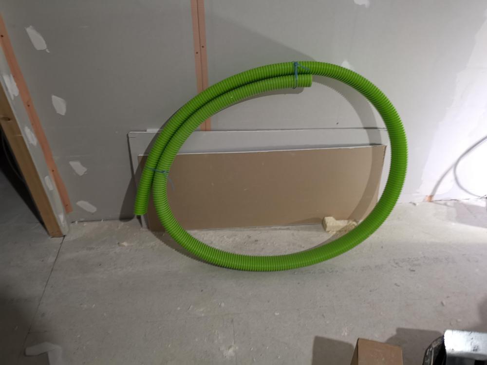
-
Hi Jack. Are you sure Loxone has native Dmx control? I thought that was a separate extension? Or do you mean KNX? I am about to start the home automation installation, including UniPi and Loxone kit alongside 24v DMX dimmers and relays. Might well start a thread about it all! ?
-
Short length of 51mm x 114mm oval?
Nelliekins replied to phatboy's topic in Mechanical Ventilation with Heat Recovery (MVHR)
Hi Tim. If it's the semi-rigid stuff you are on about I might have some Ubbink AE35SC (100x55)still left at site. Will try and get down there tomorrow and have a look see (we had a waste management company clear the site a couple of weeks ago, and most offcuts were taken then... But I remember seeing some oval in the basement the other day). If I do, it'll only be 3m or thereabouts - are you sure that's enough? Neil. -
To be honest, I'm glossing over some details somewhat! For example, that 45-degree wall was interesting to brace, mainly because it wasn't exactly 45 degrees. After foaming the wall joints, I was wondering how to brace the wall properly. My builder-come-consultant had a genius idea. We ended up creating a hinged OSB screen (using a bunch of standard door hinges), so that we could form each of the angles independently. Then we screwed the OSB to the webs in the ICF blocks to make it solid. Then we put CLS timbers across the OSB, and bolted together, to give it more rigidity, and bolted the CLS timbers together. Worked a treat. You can see the detail in pictures 4 & 7 above. Lifting the steel beam was a challenge, too. We attached ratchet straps around the uprights for the scaffold system (one in the kitchen side and one in the garage side, and clamped into the web with timbers), and then used spare ICF blocks from the basement walls as chocks to insert every time we got another 400mm up. That allowed us to adjust the straps safely each time, and start again. The problem came when we got to the last block - one ratchet snapped, and the beam dropped at the back. Thankfully we were (sensibly) working from above (on the scaffold) at that point, because if it had hit someone below we'd have needed an ambulance. The final 700mm of lifting for the back end of the beam was done by myself and 2 mates on our shoulders, once we had lifted the front end onto the garage wall and secured with metal strapping so it couldn't fall off. And boy, was it heavy! Now that I am getting a bit of personal time back, I'll start trying to include more anecdotes like these in the blog - it's just been mental levels of stress the past few weeks (Dad in hospital 200 miles away, and my day job looking like it's about to end right when both mortgages are at their peaks...)
-
That's the point - we had a topo done (cost £420) prior to completing the excavation of the basement hole - all setting out was then done by a setting out engineer (at a cost of £350) based off the topo. They just misread the topo somehow, because our only height datum was the DPC on the neighbour's house, and all the measurements were calculated using that as ground level (when clearly it wasn't). By the time we realised the problem, we had concreted the ground floor walls and built the first floor walls up. Our choice was either to have lower ceilings on the first floor (and I am not a fan of low ceilings - the basement is over 9' and we're at 8'4" on the ground floor), alter the roof pitch, or get the planners to let us have a taller house than either side. I vetoed option [1], and we had had enough dealings with the planning dept at this point to know option [3] was unlikely, which only left option [2] - alter the roof pitch. It still required a new planning application, but because it was obvious why we were making the change, and because it was obvious we weren't trying to make space for a future loft conversion (it's only 1.4m clearance in the loft now), the planners were much more accommodating.
-
Because then there's nothing to seal any tray against... That seems to be a bad idea, given everybody here appears to tank and then seal trays / formers against a tanked wall!
-
As it happens, it was a bit of both. The setting out engineer had taken the wrong reference point for the setting out of the basement slab, testing the neighbour's DPC as ground level instead of 140mm up from ground level. But the bigger problem was the neighbour's "measuring" of their eaves height. Our solution was fairly simple - just reduce the pitch of our roof to accommodate the planners' desire for our ridge line to stay below the neighbouring houses. Our roof was never going to be converted because it was already too shallow, so dropping another 2 degrees of pitch from 27° to 25° wasn't a huge issue for us. I wouldn't have been able to stand up in the loft regardless. However, it did mean slightly less effective solar PV, especially in the winter months. Ho hum!
-
Not yet! That's late spring covered, next up is summer 2018, and the roof going on and windows going in!