


SBMS
-
Posts
1064 -
Joined
-
Last visited
Everything posted by SBMS
-
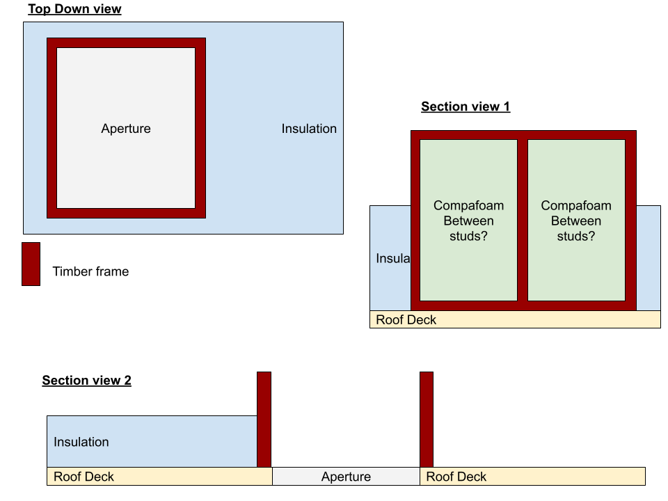
Thanks - and in between the studs of the timber upstands goes compafoam (my section view 1) or could I infill with the PIR?
-
@JohnMo thanks for this - am still a bit confused with the makeup.. Is it like the below (tried to show it from a few angles). So build a tinber frame around the aperture, then fill between studs with compafoam with levels as you mentioned?
-
Thanks @Onoff. He probably does have a mate, just wanted to make it as frictionless as possible. And if I can pay a few hundred quid to get it inspected by the BC at the end that’s nice and easy?
-
Also - is the compacfoam effectively infilling the frame around the top of the aperture?
-
I’ve often heard Sparky’s don’t like signing off others work - could this cause an issue finding someone or could we just get an EICR report from a third party as sign off?
-
Thanks! So it sounds like there is a mechanism for them to inspect. We will be using a private BC so will need to check with them
-
Would there not be thermal bridging that we are trying to avoid where the timber frame connects to the roof deck? is the roof light aperture to the left in your section diagram?
-
I wondered whether BCO would accept a third party EICR post completion, if they did ask?
-
It’s a possibility, I just wondered if there’s a possibility for BC to sign off.. if you were competent enough to do it yourself for example but weren’t able to self certify can BCO sign off?
-
Father in law is a retired electrician (retired last year) so no longer able to self certify. Was considering him doing the electrics on our self build. I know that another electrician can sign it off on their behalf (which is frowned upon). Is there a mechanism where building control will sign off the electrics without the need for self certification?
-
Do you mean build a frame that’s 100mm away from the aperture around the aperture. And then on the ‘outside’ of this frame the PIR butts up to it and the inside the compacfoam? struggling to visualise what you mean
-
Thanks @JohnMo got a video of it online. This looks like a great idea for our upstand. One problem is that we are doing warm roof construction so putting 165mm insulation on top. Compafoam looks like it’s max height is 150mm and I think regs state the upstanding needs to be 150 above the finish roof level. Would you do 150mm compafoam then a 165mm timber frame on top or two layers of compafoam to build a 315mm upstand?
-
Is the whole of the upstand made out of it? Have you got any pictures or details? cheers
-
Ah damn, now you’ve got me thinking of insulated up stands - never even realised this was a thing…
-
Anyone got any recommendations for a cost effective flat, fixed roof light for our flat roof that achieves 1.0 u value or lower? We need two and they are each 2800mm x1300mm.
-
@Dave Jones when you say calculating heat loss ‘through’ - isn’t both sides of your marmox insulated? CWI one side and the floor PIR the other? Or is this not how it works
-
Floor joists: in blockwork, on masonry hangers or on ringbeam?
SBMS replied to SBMS's topic in Brick & Block
We’ve got floors that are built into blockwork in current house. They bounce a bit on a couple of long spans but don’t squeak. anyone else any experience with hangers? I wonder if we should specify 400mm spacing if we go with hangers.. -
Floor joists: in blockwork, on masonry hangers or on ringbeam?
SBMS replied to SBMS's topic in Brick & Block
Did you seal around the hangers for airtightness? -
Interested to hear people's thoughts here - how did you fit your intermediary floor joists? A very quick comparison: Built into blockwork: quick and easy for brickies, no squeeky floors, difficult to airtight (Tony Tray needed) Joist Hangers: better for airtightness (but detailing still needed to account for mortar drying, timber shrinking), pre-engineered by posi joist designer, have heard they move and can be squeaky Ring Beam: ideal for airtightness, brickies and just construct the walls, more work to construct, structural engineer needed to specify bolts and sizes etc, again have heard they move and can be squeaky Thoughts?
-
Have you quantified the difference in heat loss from the increased thermal bridging? I calculated that a perimeter row of 215mm thermoblock would be circa £2k additional cost. I wonder what the energy saving would be, but I'm not sure payback justifies it? No hard data for that though, just a gut feeling...
-
Thanks, yes it's not been updated yet following SE's drawings. DPC is in wrong place too!
-
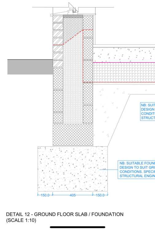
Thanks @JohnMo got it now. Out of interest how would one typically ‘stop’ the EPS beads 225mm above the concrete cavity fill? A cavity tray? FYI this is the architect detailing showing the DPC/cavity tray in red dotted line - does this catch the EPS beads?
-
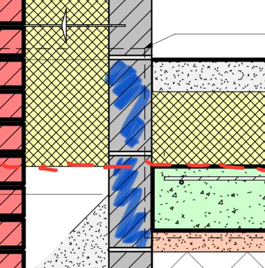
Got you. I think the thing I couldn’t make sense of is why I’ve read in a few places on here that members have taken their insulation to the bottom of foundations. In my head in only makes sense to take it to the same depth as the slab insulation (dotted red line below) Am I correct on that? So in summary, I just need to change the two courses of inner block immediately below DPC (marked blue below) to aircrete blocks and that’s it?
-
At the risk of sounding daft (I don’t mind!).. if the cavity below ground is filled with insulation, how is this thermal bridging any different to above ground - ie the same makeup with a block wall and then 200mm of insulation? Is it because it’s a solid mass below ground on the inside of the wall as opposed to mostly empty space (ie a room) above the DPC? Or is the primary reason for using aircrete blocks simply to negate the thermal bridging of the bottom most block sitting on the foundations? I hope my naivety will be useful for others!
-
Is there any reason why aircrete blocks would be needed if we brought the cavity insulation (EPS beads) right down to the bottom of the cavity? Would that negate any thermal bridging? I don’t know whether a Cavity tray at DPC level would still be needed.
