BEJB
-
Posts
33 -
Joined
-
Last visited
Everything posted by BEJB
-
Ecodan - room temp auto adaptation and multiple zones
BEJB replied to BEJB's topic in Air Source Heat Pumps (ASHP)
Being a scientist, I know you should change one thing at a time, then evaluate the impact of that. However, I'm retired, so I've had a go at:- reducing the speed of the zone 1 pump setting the zone 2 pump to the UFH setting (I think the Ecodan engineer probably changed that to higher constant speed) reducing the 'set back' of the UFH thermostat, so the floor temperature doesn't drop so much overnight. altering the wiring for the zone 2 (UFH) pump to connect it to OUT2 rather than OUT3. OUT 3 provides pump power if Zone 2 calls for heat. OUT 2 provides power if either Zone 1 or Zone 2 calls for heat. So if Zone 1 calls for heat, it heats both the radiators and the UFH - so the UFH becomes part of the zone 1 heating circuit. But if it doesn't get enough heat from that, when Zone 1 thermostat reaches temperature, Zone 2 can operate on its own. Switched the heating to flow temperature and then back to Room, to reset the 'learning' process. Of course, yet another variable has kicked in, because the outside temperature has risen by about 10C, so it is now about 13C. So of course, everything is toasty, and I won't tell if the current setting is any good until we drop back down to frosty nights. Thanks for your help. Here's hoping things are a bit better for these changes. -
Ecodan - room temp auto adaptation and multiple zones
BEJB replied to BEJB's topic in Air Source Heat Pumps (ASHP)
OK, so I might has been exaggerating when I said 'bottom'. Zone 2 is lower down the LLH than zone 1. I've tried to attach a picture. What it does mean is that the hot water just seems to be scooted off into Z1 if the Z1 pump is running, leaving nothing left for Z2. I don't know what the Z2 pump pumps through the UFH - all I can think is that it is the return water from the bottom of the LLH. When I think about it, it makes my head explode! I tend to think the whole thing suffers from poor design, caused by a heating engineer more used to gas boilers. Zone 1 is OK - the radiators have a greater capacity than the 14kW heat pump. But if the zone 2 UFH runs buy itself, I don't think the emitter capacity is up to dealing with the heat pump - the return temperature is only a degree or two below the flow. So the system starts sawtoothing. At least it is only a couple of 'tooths' per hour and the floor does heat. But for that to work, I have to have zone 1 off. Generally, I can get by and ignore it. But when the cold weather strikes and the outside temperature doesn't rise above zero for a week or so, it doe highlight these weaknesses. I think I need to follow the advice given when it turns cold - just switch to flow temperature and whack it up to 45 - and accept the bills going through the roof!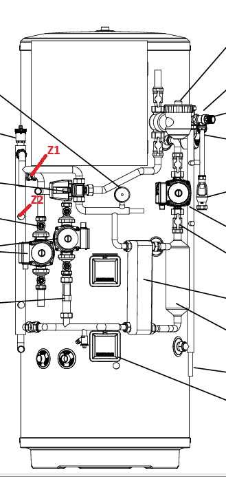
-
Ecodan - room temp auto adaptation and multiple zones
BEJB replied to BEJB's topic in Air Source Heat Pumps (ASHP)
Mmm - again, you have got straight to the point. I have a Mitsubishi preplumbed cylinder, with four pumps. It has a low loss headerm with zone1 pipes coming off the top of the LLH and zone 2 coming off towards the bottom. However, for some reason best known to the installer, if the pumps for both zones are pumping, the pipework for zone 2 doesn't get hot - all the heat goes to zone 1. So with Room setting, if zone 1 pumps all the time, zone 2 gets no heat. Sad face. -
Ecodan - room temp auto adaptation and multiple zones
BEJB replied to BEJB's topic in Air Source Heat Pumps (ASHP)
Mmmm- that is interesting. The heating system can heat zone1, zone 2 or DHW but only one of them at a time. I know DHW claims priority, but if I could have zone 1 and zone 2 independently or together, that would probably help. Thanks for the tip - that's something to look at. Interestingly, if I have either zone 1 or zone 2 calling for heat, the Melcloud app shows both of them operating. I always assumed that was an artefact of the software, but maybe it is another thing pointing to some sort of configuration error. -
Ecodan - room temp auto adaptation and multiple zones
BEJB replied to BEJB's topic in Air Source Heat Pumps (ASHP)
I think this is very true. I find it difficult to see how the auto adaptation can learn for the kitchen. It does have oven & hob, plus heat from things like the dishwasher etc. Also, it has several windows that face south-east, so gets quite a lot of solar gain. It can be quite cold outside, but if it's sunny it can be quite warm in the kitchen. While I think auto adaptation is good for zone 1, if I could set zone 2 to WC, that would definitely be worth a go. -
Ecodan - room temp auto adaptation and multiple zones
BEJB replied to BEJB's topic in Air Source Heat Pumps (ASHP)
When I first got the house , the kitchen/utility had third party controls. Dividing the UFH into 2 definitely meant the loops were too small for the ashp to heat! Anyway, I swapped that out for an ecodan thermostat,which controlled both ufh loops and so worked a bit better. It also showed the temperatures on the Melcloud reports. I do wonder if there is a setting or a dip switch that allows me to control the heating modes for both zones .... -
Ecodan - room temp auto adaptation and multiple zones
BEJB replied to BEJB's topic in Air Source Heat Pumps (ASHP)
I have the two zones but only one option
-
Ecodan - room temp auto adaptation and multiple zones
BEJB replied to BEJB's topic in Air Source Heat Pumps (ASHP)
I can't set different heating modes for the two zones. I set it for zone 1 and the same applies to zone 2. Room seems to be the best compromise. I don't know if this is just the way it is setup, or if I could change this to allow different heating modes for different zones. -
Ecodan - room temp auto adaptation and multiple zones
BEJB replied to BEJB's topic in Air Source Heat Pumps (ASHP)
That's interesting. Yes, I do have separate Ecodan remote controllers for each zone. Although I have 'set back differentials' for both zones (reduced thermostat overnight), I have less for the UFH and the UFH starts earlier, so it gets a boost first thing in the morning. I could have a go at further reducing or removing the setback differential for zone 2 and raising it even earlier (if there is still a setback differential). I'd still have the thing where zone 1 wants to just run continuously during the day, rather than heating the house so zone 2 gets a chance. But maybe getting heat overnight would be ok. I do wonder if the auto adaptation can 'learn' the heating of the two different zones - or if it pretends its just one zone and produces a sort of 'average' which is not right for either. I also think there is a design flaw, in that the two zones have very different capacities. Zone 1 has lots of rads and the heat pump has obviously been sized for that. I think the heat pump is therefore oversized for the comparatively small volume of the kitchen UFH. So it can sometimes have comparatively inefficient sawtoothing. This seems less of a problem with auto adaptation than it does with weather compensation, so maybe the auto adaptation does learn something. Thanks for your replies and ideas. -
I have a 14kW Mitsubishi Ecodan, which heats 2 zones (zone 1 = house with rads and zone 2 = kitchen with UFH) and DHW. I spent a good time playing with weather compensation only to find that room temperature with auto adaptation heats better with a higher COP - happy bunny! However, there does seem to be a slight issue. Auto adaptation seems to set itself to the lowest flow temperature to match heat input to heat output. So zone 1 heats well and is very efficient. But the system doesn't run zone 1 and zone 2 at the same time - zone 1 takes precedent if it calls for heat. So zone 1 seems to be on all the time (nice and snug!) and zone 2 seems to be off most/all of the time (a bit chilly). Does anyone have any suggestions as to how I might be able to get some heat to zone 2, while still being able to benefit from auto adaptation? Thanks in advance for any help or advice you can give.
-
When first installed, my Ecodan had a daily standby reported by Melcloud of about 2.5kWh. Mitsubishi then installed a meter and it dropped to about 0.5kWh. I think some Ecodans over estimate their power usage. Hopefully Mitsubishi will correct their firmware and this problem will go away.
-
I'm not sure I can help much. Generally, I think Ecodans are excellent, and I'm not sure there are any to avoid (?). I think the main question is whether the power measurements being discussed are taken from the Ecodan approximations, or whether they are actual measurements taken by monitoring systems - in particular for power consumption. I do think that for some models, the power consumption approximations provided by the Ecodan system are currently incorrect for standby. For my 8.5kW system, they were overestimating it by a factor of 5-6, which I can now see, having had a power consumption meter installed. The 14kW system had a much lower approximated standby power consumption. I would recommend a metering system is installed, if you can afford it - I suspect it would pay for itself quite rapidly (although I don't have one for the larger system and probably won't have one installed on the basis of cost - go figure!). Hopefully, Mitsubishi will use this information to alter the firmware, to improve the approximations for all models.
-
In case it helps, I thought I'd also try to get an idea of how much the freeze-stat function uses. So on a cold night, I disabled the heating, but let the freeze-stat function operate. It was a cold night so it was operating continuously overnight - keeping the flow temperature at 20C. I took a screenshot the next morning at about twenty-five to seven. It seemed to show it was using about 0.065-0.070 kWh per hour. Standby (above) seemed to take about 0.01 to 0.015 kWh/h. So the freeze-stat function seemed to take an additional 0.055 kWh/h (or 55W - or about 1 1/3 kWh/day if it's running all day).

-
Sorry for the delay in replying. The power supply goes from the consumer unit to the outside unit, which is then T-ed off, through the wall to power the indoor unit. They just installed a single power meter, which is before the T, so it is measuring everything - heat pump, controls, circulation pump - the lot.
-
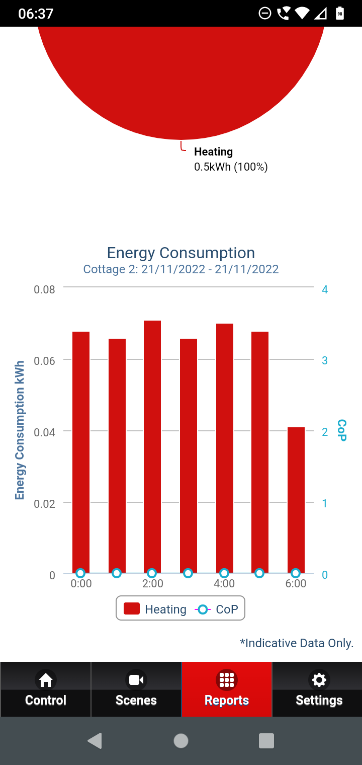
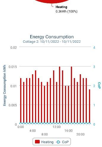
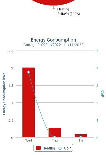
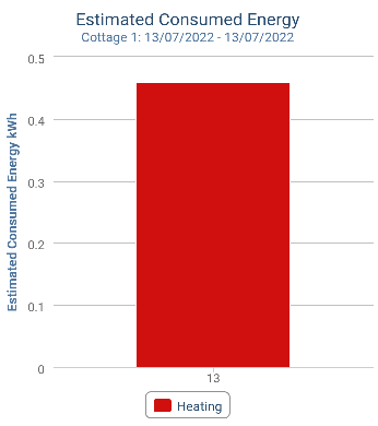
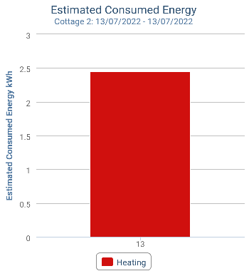
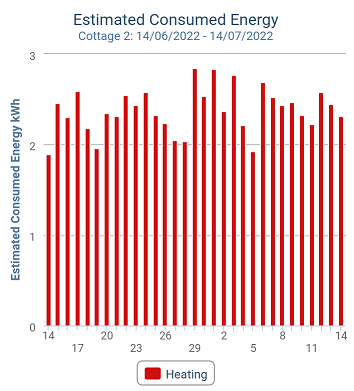
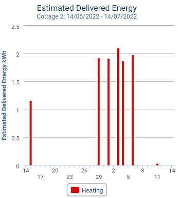
OK, I have a bit of an update. I contacted Melcloud to ask why our smaller system (PUHZ-W85VAA) had a standby figure of about 2.5kWh/day but our larger system (PUHZ-HW140VHA2-BS) had a standby usage of only 0.4-0.5 kWh/day. Apparently Melcloud just takes the estimated data from the FTC5 controller, so I checked that, which confirmed that that figure was the 2.5kWh/day. So they spoke to one of their engineers, who said the figure should not be that high. They decided that they wanted to install one of their standard monitoring systems on the W85VAA to see what its actual use was. They have done that and I ran a standby test yesterday (as it was very mild). That showed that the actual standby usage for the whole system was only about 0.3kWh for the day - or between 10-15W. I've reported that back to them. I'm hoping that it allows them to check their firmware and improve their standby estimates for people without monitoring systems installed. So all I can suggest for the moment is that if you see very high standby usage, take it very much with a pinch of salt. I've included some pictures. The first is BEFORE – estimated with no monitoring installation – standby on 13th July. The second and third are AFTER – with monitoring installed – standby on 10th November. Cheers Eric

-
Many thanks for those comments. I have been in discussion with the Melcloud team over the reports for my PUHZ-W85VAA system. The consumed estimate report shows a 'standby' estimate (ie no heat being generated) of just over 2.5kWh/day which is shocking, particularly at the cost per unit now. I have been able to turn off all other circuits in the house, so the only thing running is the heat pump (and FTC etc). Then I watched the power meter for the house (a bit like watching paint dry, and the meter kept ticking over overnight when I wasn't looking, so it has some inaccuracies). It took between 45 and 37 hours to consume 1kWh. I calculate that a steady standby usage during that time would be between 0.65kWh/day (27W) and 0.53kWh/day (22W)? This is very similar to the figures in the Standby document for a 'similar' ASHP. Interestingly, I also have my own clamp ‘smart meter’ attached and that shows a much higher figure of about 160-450w or a total of 7-11kWh/day – again as the Standby document says it would. So my conclusion s that, as it stands neither clamp meters or the Melcloud reports are accurate ways to measure the standby power usage. I confess that I had missed the fact that the estimate is actually made in the heatpump itself and just collected regularly by Melcloud. I had rather assumed that the Melcloud system itself calculated the estimate. That feels like it will make it more difficult to alter the estimation routine to make it more accurate. I'm hoping they will take this information and come out with an improved estimate.
-
I've come to this discussion very late. The hot weather has meant that my ASHPs have not been delivering heat for a month or so, so I've ended up looking at Melcloud reports that only show 'standby' figures (accepting these are just 'indicative'). And I've been quite shocked. Our house used to be two small cottages, so it has two systems. Cottage 1 was installed in 2015 and the outside unit is a PUHZ-HW140VHA2-BS. This is a larger system, and has 2 zones (rads and UFH for the kitchen) and DHW with a pre-packaged cylinder (for both cottages). There are solar panels and a solar diverter (which has allowed me to turn off the DHW recently, so I can see the standby for this system. Cottage 2 has a much smaller system that was installed in 2020 with a PUHZ-W85VAA outside unit. This just heats a few rads - nothing complicated. In recent days, when I have been able to have both systems 'on standby' the Melcloud reports show the larger Cottage 1 system (PUHZ-HW140VHA2-BS) has a daily energy consumption of 0.45kWh (equiv average power 19W). The smaller Cottage 2 system (PUHZ-W85VAA) has a daily energy draw of 2.5kWh (equiv average power - 104W). I have been in email contact with Mitsubishi and they have directed me to the Melcloud developer, to see if the reports are wrong. I think it may be possible that the PUHZ-HW140VHA2-BS report is wrong because Melcloud doesn't recognise that model number, whereas it does recognise the newer smaller system. I'll try and use my old 'smart meter' and get a clamp on some power feeds to measure more accurately.
-
I've attached the installation manual. Page 7 gives the range of flow rates for the different models. Mine is 'PUHZ-HW140 17.9 - 40.1'. I do have an option as to what to do when zone 2 calls for heat. The most obvious one is to fire up the heat pump and power up the pump for zone 2. This gives me the fast cycling and very inefficient heating of the UFH. The other option is to power up both pumps - for both zone 1 and zone 2. This could work (by providing 'thermal mass'?) and sounds like it might absorb some of the flow, removing the fast cycling. However, the zone 1 flow pipe comes from the LLH above the zone 2 flow pipe. So the heat all (or virtually all) goes down the zone 1 flow, leaving nothing for the zone 2 flow. I could rebalance the radiators in zone 1 closing them down, so some flow is left for zone 2 when both pumps are on (plus lowering the pump rate for the zone 1 pump). However, it feels like this would mean that, when just zone 1 is on and zone 2 is off, that remaining heat would continue down the LLH and would provoke cycling again (albeit probably slower). Really struggling here Ecodan_FTC5_Pre-plumbed_Cylinder_Installation__Operation_Parts_Manual.pdf
-
I had done the pump to the ufh but not the others. I've done them all now and they all seem to be ok. At least the temperature has dropped a bit now, so testing the heating is better received by the rest of the family! I've removed the Salus actuators now - I'm not sure they are set up correctly and also they seem to close the actuator valves down a bit when you attach them, even when they are supposed to be open. At least I should be able to see if I get some heat through to the UFH at all.
-
I'm pretty sure the LLH is on the right way up. It is a pre-plumbed unit, looks exactly the same as all the photos, with the vent at the top and the correct inlets/outlets in the right places as you go down. 100% certainty is impossible but I think that is unlikely to be the problem.
-
I suppose what I meant was the sizing is all wrong. The ASHP is around double the capacity that the UFH has to handle the flow and dissipate heat. Does that make sense? I'm not sure I follow your comment about zone 2? What I was trying to describe were my attempts to raise the flow levels to match the primary. I removed the flow meters (which restrict the flow and I didn't have the actuators fitted, so the actuator valves were completely open. So there was no real restriction (apart from the pipe capacity/friction) and the water could flow was fast as it liked. When I did that, there seemed to be about 10 cycles an hour rather than the normal 6. The only thing I could think was that more of the heat was getting to the return than before - so maybe it was moving so fast, it didn't have time to dissipate the heat into the floor slab. There is probably another explanation but I couldn't think of one. Any other ideas very gratefully received!
-
I'm glad you found a use for those reports too. I'm also very envious. Despite having thermistors on the zones, I can't get the flow temperatures for the zones like you can. I asked Mitsubishi support and they said you can't get them on a simple 2 zone system. For something like the problem I am having, it would be very useful if I could!
-
The Ecodan documentation says that the flow rate for the heating primary for a 14kw Ecodan is between 17.9 and 40.1 L/min. The service says mine has a flow rate of 18L/min. I have three loops on the UFH, each with a flow meter that goes up to 4l/min. So the total is 12L/min as a maximum (it is actually below that - say about 10. I did remove the flow meters and put blanking plates in to remove any obstruction. Actually that increased the rate of the cycling. I think the hot water was travelling so fast that it wasn't losing heat fast enough. I think I have hit a case of very bad heating system design
-
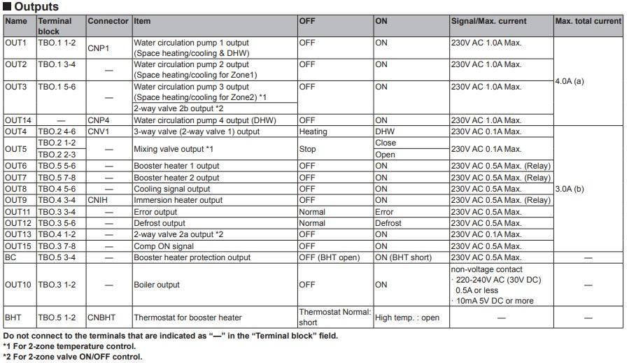
I am becoming increasingly convinced that the UFH just doesn't have the capacity to handle the heat coming from the heat pump, and hence the fast cycling. So there are a couple of 'solutions' that I'm thinking about at the moment (but always open to instructions not to be a dolt, or other options to consider!). First, I wonder about adding additional items to the UFH heat manifold, to 'absorb' the heat and hopefully heat the kitchen. I could extend the manifold and connect a radiator into the room (as it is an ASHP, it would have to be a large triple radiator). Alternatively, there is a lobby areas just outside the kitchen - I could disconnect the radiator in that (currently in zone 1) and connect it to the UFH manifold. Neither are great solutions, but they might help. The other option I'm considering is a 'feature' of the Ecodan FTC5. I've attached a copy of the outputs for the FTC5, For 2 zone heating with pumps for each zone, Mitsubishi say that zone 2 pump should be connected to OUT3 and zone 1 pump should be connected to OUT13 (apparently, the 0.1A is a typo!). One reason for this is that, if zone 2 is on (OUT3), then there is also power at OUT2. If the zone 1 pump were connected to OUT2 (as intuitively seems sensible), then it would also come on when the zone 2 pump (OUT3) came on. So I'm wondering about connecting the zone 1 pump to OUT2, rather than OUT13. So when the zone 2 UFH came on, so would the zone 1 radiators. So there would be enough radiator capacity to handle the heat provided by the heat pump, and there would be no fast cycling. It is true that the heat would go to the highest point in the low loss header (zone 1) . So I'm thinking about balancing the zone 1 radiators down, so there is remaining capacity to pass to zone 2. This doesn't seem ideal. I wonder if that might mean that when zone 1 is on by itself, the radiators might then have insufficient capacity to handle the heat - so once again heat would go down the low loss header and I'd get cycling. The balancing seems quite sensitive. It feels like I need a variable valve that allows full flow to zone 1 when it is operating alone, but restricts the flow to zone 1 when zone 2 is operating. As you can tell, I am very much an amateur at this, and easily get myself into a tizz. Any help is much appreciated Eric
-
I don't think there is a valve of any sort that can help here. Obviously there is the three way valve to select if the heat goes to DHW or to heating. There are on-off valves either side of the magnetic trap. There are on-off valves either side of the UFH. But I think that is it I'm just wondering what your thoughts are about return flow from zone 1. From my perception, zone 2 operates, but a substantial amount of the flow goes down the low loss header rather than the UFH. As a result the return thermistor returns a reading that is only marginally below the flow. The temperature of both rises, until the the heat pump cuts out. At that point, the pump for zone 1 cuts in (and zone 2 pump continues). This seems to result in some heat passing into zone 1 and heating the radiators a bit. colder water emerges from zone 1, cooling the water through the heat pump, low loss header and the start of zone 1 & 2. After a pause, the cycle starts again.