ian192744
-
Posts
24 -
Joined
-
Last visited
ian192744's Achievements
Member (3/5)
2
Reputation
-
Mitsubishi vs Samsung Heat pump
ian192744 replied to Slippin Jimmy's topic in Air Source Heat Pumps (ASHP)
answering the HA integration: best way to do it with samsung is to install the modbus module MIM-B19 into the outdoor unit. Then modbus to HA machine (or modbus to an ESP, ESP to HA). I use this and it works well. My original intent was to use it for control and I do have the ability to do so, but I mainly use it for monitoring, I can see pretty much everything. for some idea what you can track: my system is https://heatpumpmonitor.org/system/view?id=45 on heatpumpmonitor. COP's are ok 4 ish in milder weather, but drop noticeably below 3 once temp is below 3C or so. Probably a newer on like the Vaillant would do better, if I was choosing again now that'd be on my shortlist. I can get my samsung 16 down to 4kw but thats pushing the lower boundary. I have a 200m2 1973 house, my house needs 10kw when its -3C, 4kw when its 7C . so its ok. but from what I've read on other fora, the 8 doesn't get down as well , can't do 25%, more like about 3.0 kw. If your house is 100m2 and well insulated 2019 new build then an 8kw samsung will be too big, its minimum of 3.0kw in mild weather will be way overpowered. make sure you research the minimum turn down of the options you are looking at. (most mfrs won't tell you, you need to glean from other users on fora). Are you able to carefully measure your current gas boiler use to workout your heat throughput? -
just wanted to add my 2c to this. The figures in the Graham Hendra Freedom HeatPumps video here are the wrong way round. I recently self-installed samsung 16kw. followed grahams video's for setup. couldn't get my head round my radiators running cooler when we got a cold snap. the manuals are all very well but they don't say which numbered setting is on the right and which is on the left, and the screen doesn't say which one is which number. not ideal by samsung. anyway in 202* the "Low Target Value" is the lowest LWT temp value that you want to use when its mild . The "High Target Value" is the highest LWT you want to use when its cold.
-
near milton keynes. If there are companies that can do this, then any specifics please? yes have considered EWI but the house is quite an awkwards shape, quotes have been in the tens of thousands. so want to re-look at this first. also someone made the point to me that if the cavity has air in , then air will circulate in there, thus reducing the performance of EWI
-
Hi , My house is 1973 built, exterior skin brick, interior concrete block , cavity wall, detached. The cavity varies between 40mm and 80mm approx. I don't know why its not consistent or so small, it just is. The cavity contains 20mm of a very "old school" polystyrene board - somewhat like what would have been used to package a TV in 1970's or 1980's for those old enough to remember that far back. The type that fragmented into small white balls at the slightest poke. The board isn't even particularly well fitted - from the small bits of the cavity that I've had open at various time, its simply loosely laid in there not fixed. It is not a modern system at all. so the insulation is not brilliant, as you might expect. Every "bog standard" cavity wall company that I have had round over the years, after survey has said they won't touch it. All for understandable reasons - not enough remaining cavity gap to work with , danger of getting cold spots with an incomplete fill, risk of the existing polystyrene board fragmenting etc. I'd sort of given up on it but now that I am trying again to improve the fabric, its the first thing again that comes to mind again. Can anyone point me at a company that might have a solution for this? thanks Ian
-
LLH/Small Buffer - Pumping direction
ian192744 replied to ian192744's topic in Boilers & Hot Water Tanks
thanks. sorry but your diagram loses all detail with the screenshot resolution. however, I have studied dozens of similar diagrams , plumbing and heating websites, watched umpteen design videos, and it does seem to be common that the pump for the secondary circuit is shown adjacent to the buffer pumping away , but nowhere can I find a reference that says that this is the right thing to do. DHW is in a 1 year old 300L UVC (which nick steered me towards after a previous discussion a year or two back) and has a HP size coil so not changing that. the buffers I've been looking at are this https://lovatospa.com/gb/product/49017080/bomber-20-hybrid to fit without difficulty, or possibly, with some inconvenience and significant re-arrangement of the airing cupboard, this https://lovatospa.com/gb/product/49017084/bomber-50-c (which does have an immersion option). I REALLY want one that will flat-to-wall mount because of where it has to go. so many uk supplied buffers seem to be just cylinders and thus take up a lot of space projecting outwards. great if you have a plant room, not so great if you don't. boiler is a heat only, no pump, hence the question. Currently pump is away from boiler into rad circuit (at the mid point). -
LLH/Small Buffer - Pumping direction
ian192744 replied to ian192744's topic in Boilers & Hot Water Tanks
+info wouldn't let me edit above post.. too slow ... MCS heat loss for my house at -3C is 14-16kw depending on room temp assumptions. Boiler has been flow-temp limited to 55 for the last year and half. gas load monitored on 30 minute intervals, I know we're comfortably inside 16kw almost all the time. -
LLH/Small Buffer - Pumping direction
ian192744 replied to ian192744's topic in Boilers & Hot Water Tanks
hi nick The e-boiler is a backup for if the rest is broken, just heat a couple of rooms . Many ashp have a backup heater - I'd rather get one without a backup heater and have the backup contained in a separate device (so its a proper backup!) . Its also to heat 1 room regularly . the house has just 1 room occupied during the day 4 days a week - just my study - and I detest having to run the gas to heat this when I could use electricity which is either low-carbon (Tou into battery ) or from PV, so cold sunny days in feb-march-april it will be free. none of this is predicated on cost saving with ToU tariffs (which I happen to believe will continue, but thats by the by) just a nice to have. why would a 20L buffer be unsuitable for this design? not big enough? there are 16kw heat pumps (e.g daikin) that are specced for a min vol of 20L which is why I am at that figure, its not a made up number. 100L would be really difficult to find a space for. there is no intent to run heat sources simultaneously. the heat pump in the diagram doesn't exist and won't for some time.A2A non-starter - whole house is rads. This isn't a major rebuilding project. any thoughts on the actual hydronics question or do I need to look elsewhere for that? cheers Ian -
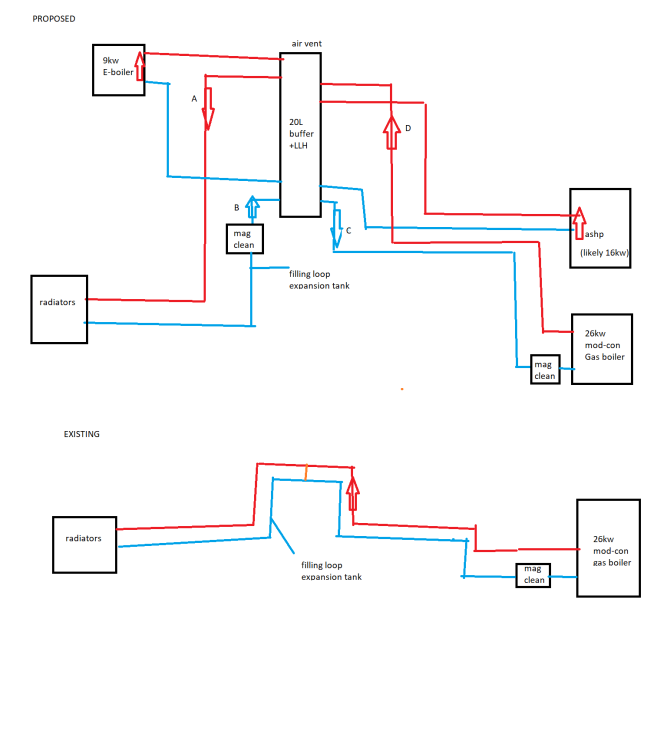
hi all interested in the hydronics wisdom with regarding to pumping direction relative to an LLH / small buffer. Some system components like ASHP have their own pump so that is a given, it has to at the far point away from the LLH. however for a loop that needs its own pump (rads, and a heat only boiler), the pump needs to be sited physically close to the LLH in my case - there is no where else it can go. Should it pump away from the LLH (positive pressure into the circuit - pumps A and C ) or towards the LLH (positive pressure towards the LLH - pumps B and D). I'd have expected from the physics of it that you'd want the positive pressure going into the circuit , but struggling to find any decent reference documentation on this? reasons for system design - existing system is not great . looked at it all sorts of ways, we have a flow rate problem. all the loops are long and bendy, big house, lots of rads, TRV's on all. boiler short cycles a lot, and in fact has been known to not fire due to not enough flow rate when TRV' drop down. separating primary from secondary will give full flow to boiler, and allow pump tuning for the needs of that loop, rather than the current which is a compromise. - will put in an e-boiler (as backup for the gas) asap. cheap and cheerful , doddle to install, and running on 40kwh of octopus go stored in my 3x powerwalls its a wee bit cheaper than gas. - intend to add an ASHP next year but will keep boiler. not been able to pin down a vendor or installer yet . capex for a 16kw + install struggling to make sense of right now. but 20L LLH buffer future proofs it. looking at a buffer with internal baffles / directed take offs to maintain stratification ta Ian
-
did either of you solve this question? I have honeywell evohome with opentherm to mod-con viessman boiler. looking for an ASHP that can consume third party stat input (large house, need programmable TRV's for reasons much discussed already, I know I'll need a fair-size buffer to maintain volume when TRV's shut). if ASHP can consume opentherm instead of on/off, so much the better.
-
planning my ASHP location, and pipe route to get to where all the rad circuits distribute from and likely buffer location - 1st floor airing cupboard. seems to me like my easiest option will be to go outside , up from ground level , round an awkward corner, then up the side of the house to roof level (2 story house), then into the loft space, across the loft then drop into the airing cupboard. If I go for the option of "get inside as soon as poss", the internal route will require a whole lot of lifting of boards (chipboard - 1970's house so a pain) , lots of joist drilling / notching and we have to go through 2 external walls (there's an extension that causes this to be 2 not 1) - all quite a lot of hassle and time consuming. Plus with 32mm pex, thats big joist holes. Prefer not 28mm copper as seriously pricy these days. whereas the external route for my house I reckon is do-able really quickly , mostly DIY able , and little/no major hole drilling. once into the loft, I can bury pipe under insulation and the routing is easy. Question - has anyone used pipe like this https://ingoodnic.uk/25-25-90mm-2.html ? I'm thinking 10m of dual 32mm preinsulated as 32mm has more or less equivalent ID to 28mm copper which seems to be the recommended by most installer. It'd go the side of the house and in through a hole in soffit into the loft space. No wall drilling. My soffits are really wide so room for bend radius should not be an issue. It'd be in a non-visible corner so no issues with spoiling appearance or similar. ta Ian
-
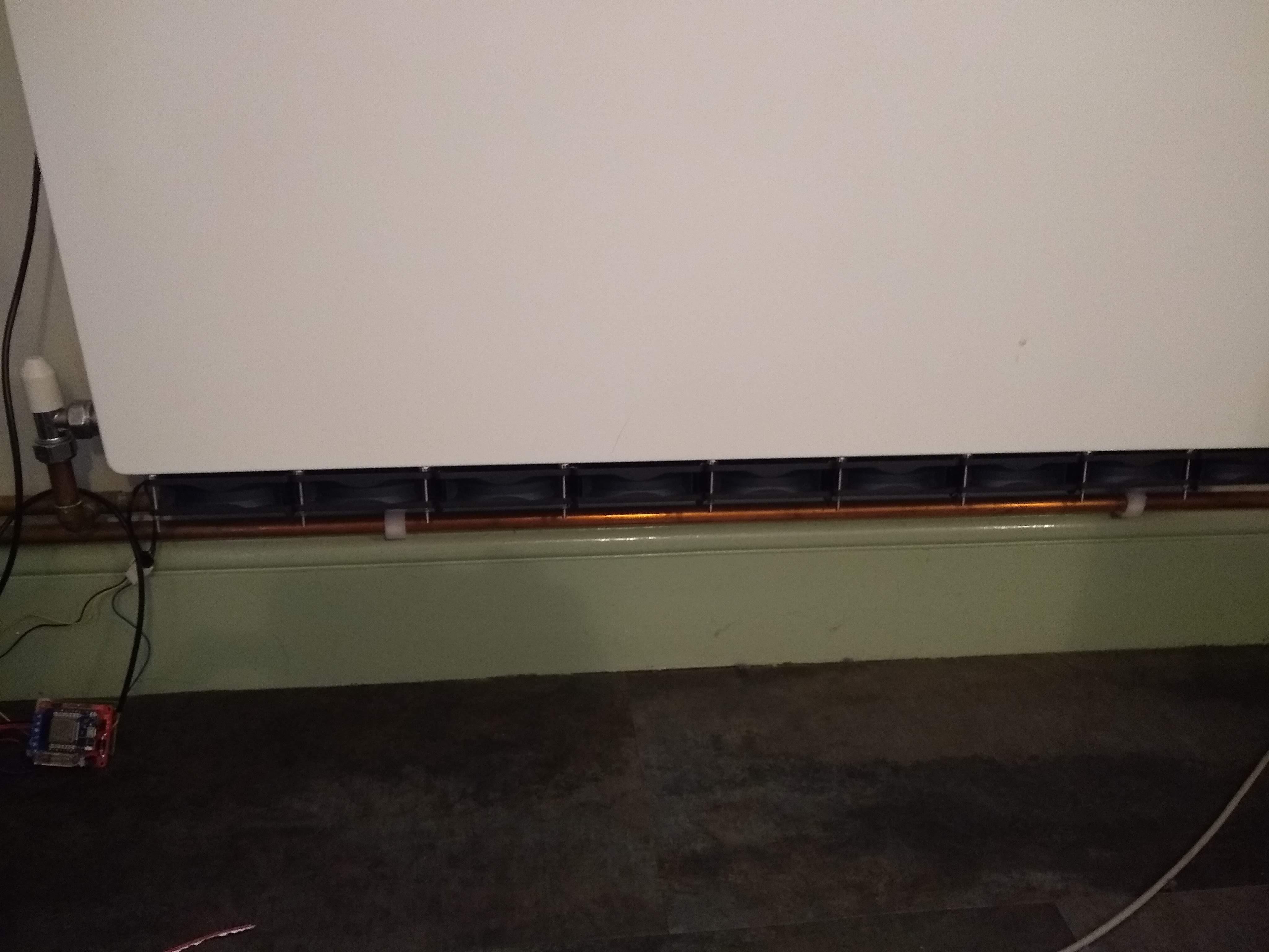
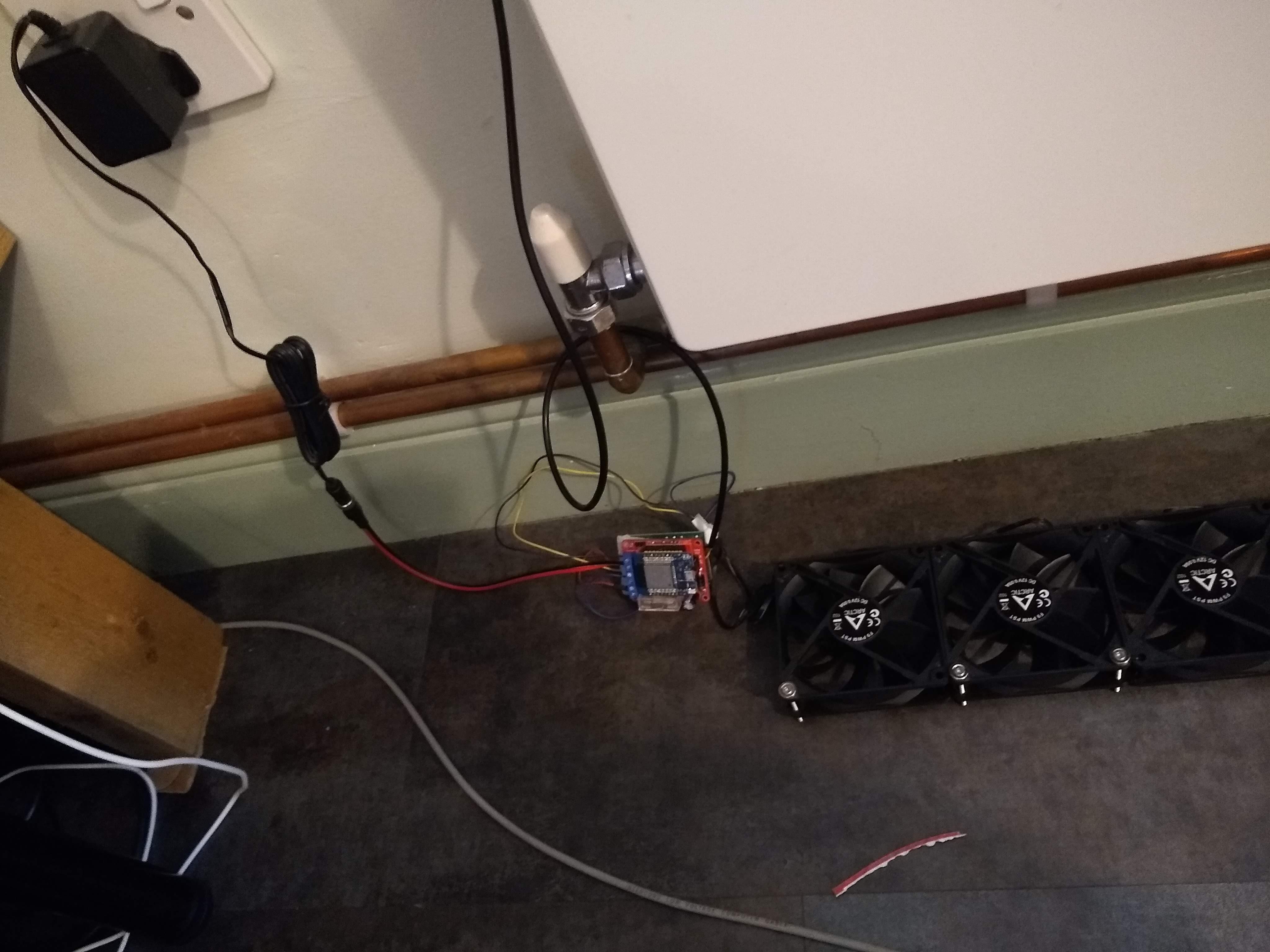
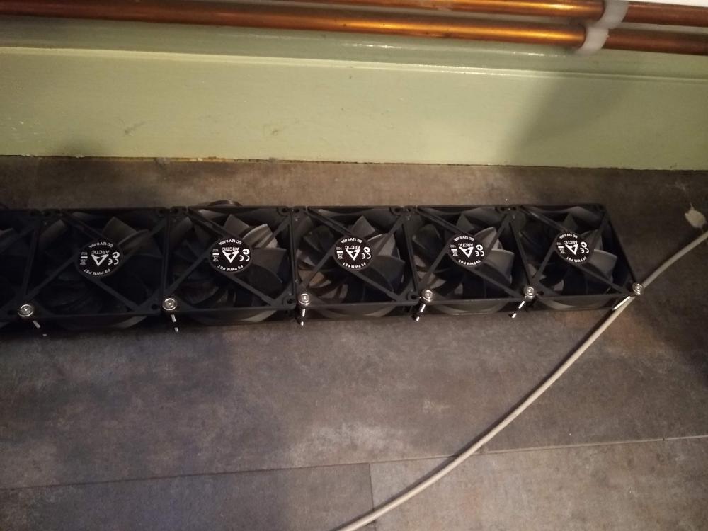
there's absolutely no vibration. I bought a 100pack of these guys https://www.ebay.co.uk/itm/144017582577, as long as the rad is the right shape to get a good contact, they won't move. PWM allows you complete flexibility with fan speed if you're unlucky enough to find a resonance at some point. But a bit of neoprene superglued around the contact points would be easy peasy to add if vibration damping was needed. I used to have a bit of an obsession with SilentPC's, I'd always build my own in the days when aircooling was the only option. I now buy fully passive heatpipe+heatsink and/or All-in-One water coolers for PC's that I uses, but its given me the background on building for airflow and near-silence at the same time. Mid-spec PC fans are really quiet and don't cost the earth. The arctic PWM PST fans are so useful because they come with the daisy chain connectors as part of the design - so only one upstream connection for as many fans as you like. I was thinking about top vs bottom of rad as mount point for cooling as well, although I don't have a cooling capable source yet. One bonus of magnet-held setups is that you do have the option to simply move it from the top of the rad to the bottom or vice versa. rads with less than 80mm depth are indeed a problem. depending on what else is below the rad you could mount an 80mm fan on an angle (lower end toward the wall, some trickery with clips into the skirting to hold that side up). I tried this with a K1 rad and it was ok but not great, obviously significant airflow wasted going behind the rad into the unheated space. I didn't experiment with blocking it. unfortunately I haven't found any 60mm fans worth trying - of course they exist, but they are all designed for comms room / datacentre environments where low noise is not a thing - plus to cover the length of the rad, you need loads. I think 80mm is the smallest worthwhile. I think something like this https://www.amazon.co.uk/Myhomeware-Radiator-Adapter-Diverter-Booster/dp/B07LGCXQZV?th=1 should be easy enough to make , in order to divert air away from curtains at the top, and if reversed with fans blowing down from the top and mounted underneath, could probably form the basis of a condensation drip catcher for cooling. I haven't done anything about that yet though. the other thing to think about is that if you CAN fit a K3 rad in for depth, then you'd have space to use 140mm fans which will have loads more airflow and you need less to cover the length - you could then make the rad smaller in either height or length. basically I am trying to avoid having to replace all my rads, especially not put monster K3's in everywhere. I'd rather have a K2 with a fan. having looked at the design of some of the commercially available FCU's , I couldn't find any where I liked the way they worked (fans too small, not controllable enough, no noise specs on the actual fans themselves - only on the overall unit) and/or pricing levels are very high compared to that of a rad plus some fans. And being a bit of a tinkerer I thought I'd build my own! I'll be building the mk2 at some point soon, I'll take some more detailed pics. Ian
-
this answer your question? obviously its all off right now....
-
I looked at the commercial units and decided a) too small b) no control over the quality or noise level of the fans used (undoubtedly cheap crap) c) quite pricey for what they are so I'm building my own. Fitted unmounted controller ler fan unit components: Arctic F9 or F8 PWM PST Fans (daisychained) Cable ties to hold the fans together Circular Neodymium magnets with countersunk holes, Bolts to hold them on Magnets itself to the underside of a flat panel K2 rad very nicely. Not nice enough to be commercially sold obviously , or to be on display to the world, but if its out of the way or you're not fussed about elegance, its ok. control unit: 12V PSU ESP32 controller , PWM output for fan speed, 3.3v (ESP) ->5v (FAN PWM) level shifting . Using a board from https://www.mottramlabs.com/index.html 12V relay for fan power on/off DS18B20 temperature sensor (gaffer taped to back of radiator) All run from ESPHOME and HOMEASSISTANT Photos are of the prototype version, tested end of 2022 winter. Temp sensor turns on the fans when rad is over 30C, ESP32 PWM controls the fan speed between 20% and 35% up to 50C flow. Its silent, and generates a noticeable improvement in room warmup time (I have not measured scientifically just by the "does Mrs Ian put more jumpers on or not" test....) I currently have a gas boiler was running it at 50-55C flow (with heating only of course!) whilst testing this in preparation for ASHP hopefully later this year. Ian


-
What large bore Plastic Primary Pipe for ASHP?
ian192744 replied to ian192744's topic in Other Heating Systems
so at 26mm ID its the same bore as 28mm copper so flow rate calculators that assume 28mm copper should be valid. And the compression fittings make it do-able with a spanner. that is really excellent thank you! presume the crimp fittings need the right crimp tool (that your plumber had?), looks like they are about 100 quid, worth having if you are doing lots I guess. -
What large bore Plastic Primary Pipe for ASHP?
ian192744 replied to ian192744's topic in Other Heating Systems
brilliant thanks jenni. that is way cheaper than any copper solution. Do you know what the inner bore size is for that pipe? What fittings do you use to reduce it to 28mm to connect to the rest of your system?