mistake_not
-
Posts
80 -
Joined
-
Last visited
Everything posted by mistake_not
-
An option (not saying it's good) is silver foil. Mist spray the glass with water from a sprayer and it will stick perfectly. Just make sure you don't scratch anything.
-
ASHP schematic - Noddy question - CCT
mistake_not replied to crispy_wafer's topic in Air Source Heat Pumps (ASHP)
If you are just doing UFH you should be able to eliminate everything except the 3 port valve to go between the hot water tank / heating (assume you are doing PDHW?) You should have a super efficient system just running the HP flow and return to the UFH (fully open). Obvs if you are paranoid about cookies add a heat diverter (urban plumber had a good vid showing esbe mixer and overheat detector in series) but I wouldn't bother. Only gotcha I can see is making sure you have enough water volume for defrost cycles and ensure you have an expansion tank. (I don't know the cooling set up requirements) -
For sure. Also min flow temp if it's a figure given.
-
Ah that's really interesting to see- thank you. Makes me think I should look at something similar for pumps. Given the price of the quotes I have received a self installation (+sparky) might be on the cards...
-
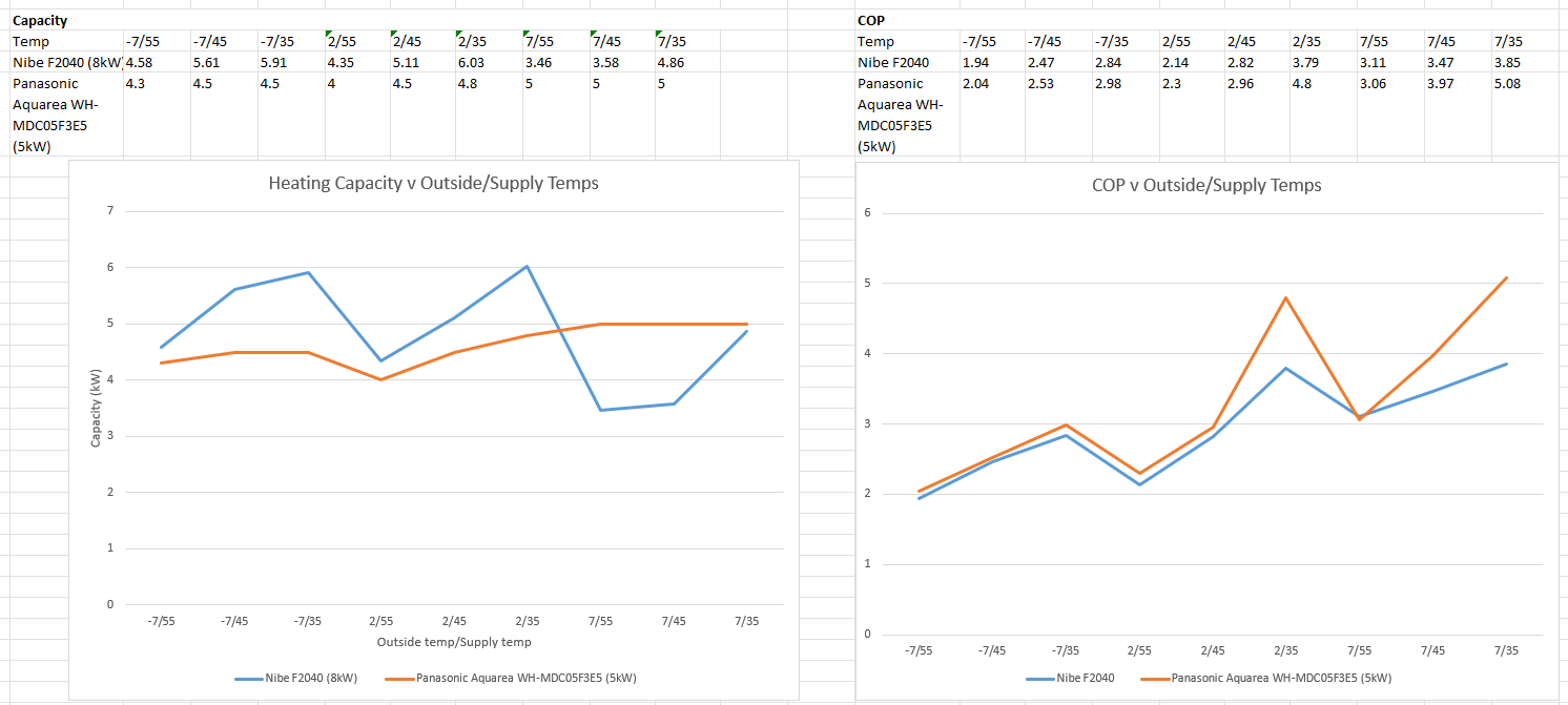
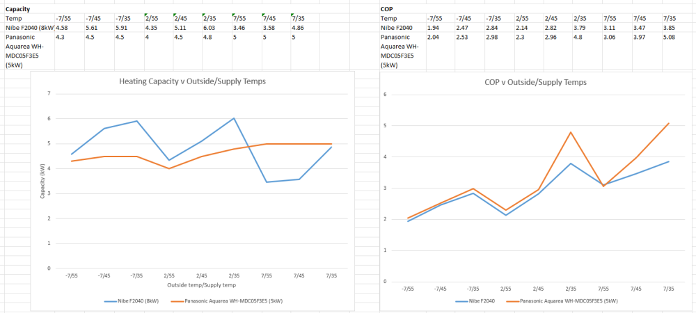
Really useful thanks @jack. I took a quick look at the Panasonic unit and on the face of it the specs look good and folks seem to have been able to integrate fully to HA using ESP32. Annoyingly the image seems to have a problem and won't load 😞
-
Yeah, seems like a 10p resistor they charge £300 😬
-
So, now that lovely discussion is out the way. Anyone got recommendations for a 5kw pump that does heating and cooling? Obvious candidates are Viessman and Valiant but I know nother about HP manufacturers really. Only requirements other than heating and cooling is integrated into Home assistant so I can keep the cooling point above the dew point, and (probably separately) do weather comp for heating. Plan is a simple open system, no zoning, have enough water volume to not need a buffer, and have bug enough pipework for dt5 flow rates.
-
Wait x months* and I'll have some data... *Where months may be years....
-
This is my plan: avoids condensation faff / risk.
-
I'm going to replace rads with fan coils upstairs. My downstairs doesn't get too hot, so a few degrees reduction via the UFH is good enough. If I get more then bonus 😄
-
Yeah, the one quote I have had (based around 5kw pump, no rad changes, leaving water tank, but including boiler rip out) is something like 7k after grant 😞. Tempted to see if the sparky that did my solar can do something with me so I get BUS.... I want a very simple fully open loop weather comp system, I already have PDHW and my pipework is all big enough already.
-
Whilst it does have that deleted, it also has custom ones and I have made sure they match the as built values. Seemed like a pretty steady output over that night though, and it's wasn't sunny days. But agree it's likely somewhere in the middle. My gut feeling is the ability for the heat pump to modulate will be more important to me than max value. I had a quick play when you first posted about it. All my u-values are as built, so I'm guessing I'll end up v similar but will give it a go. Does anyone know the deal with BUS / MCS? Do they have to hit heat loss calcs exactly?
-
Hi all, Contemplating to moving to a ASHP over the summer (mainly for cooling benefit from UFH and fan coils). Doing my heat calcs I have a big difference between my calculated heat loss and real world heat loss. Hoping someone will help me understand the difference. Calculated heat loss is around 5.1kw using the freedom heat pump spreadsheet (attached). I used the same target temps as we have in real life, and the output figures match those generated from loopcad when I was using that. Real world I got data from my smart meter. I used a night in Jan that was -2, so no solar gain etc. This real world figure gave me 3.2kw. So what do I believe? I don't want to have an oversized heat pump and want to run the system on weather comp. Other info is we find we can heat the house quite nicely just running the UFH, and leave the rads off upstairs. Means downstairs is at 19.5 and upstairs at 17. Thanks 👍 😊 Heat loss calcs 20 HCR.xlsx
-
Patio rail system - thoughts?
mistake_not replied to mistake_not's topic in Landscaping, Decking & Patios
Fyi link: -
Patio rail system - thoughts?
mistake_not replied to mistake_not's topic in Landscaping, Decking & Patios
Ah yes good point. In my head I'd just lumped pedestals in together with rails as: things that support slabs and (potentially) make my life easier. New question: anyone got experience of pedestals! -
Anybody got any experience of laying a patio / slabs on a rail system? I am (probably) going to do a patio later this year and contemplating using something like this. Seems like it helps with drainage next to the house and would be a lot simpler to lay (as long as the pads are on something solid). Something like this: https://www.rynosystems.com/pave/terrasmart-rail/
-
For design I got a lot out of loopcad in a Virtual Machine so I could do repeated trails.
-
Ring final earth leakage fault-running out of ideas!
mistake_not replied to FlatMax's topic in Consumer Units, RCDs, MCBOs
You can do the very slow and boring resistance testing.... Disconnect at CU completely, then test resistance between cables pairs at every socket and see where resistance is lowest. Might tell you when you are closet to problem. -
Downdraft Extractor Ducting Route
mistake_not replied to carson321's topic in Kitchen & Household Appliances
Before I decided to install MVHR I was going to go outside and use a Naber Compair tower as an outlet. Had all the baffles and nice things to not leech heat. In fact I got as far as buying one that's still sat in my garage.... https://forum.buildhub.org.uk/topic/42930-naber-compair-tower/#comment-604747 -
I'm not sure you need membranes / materials for a lot of that, depends what exactly you are doing. Probably just a normal polythene DPC between block and beam and insulation Insulation that's well taped and foamed might not need anything above it before liquid screed. Normally the membrane (if used) would be above insulation, below pipes. You want your pipes to be in the screed to transfer head. Re between screed and floor - depends what wood. Some supplies will want a super level finish before wood and will apply a smoothing compound, some planks can go straight on top. Hope it helps.
-
Fine tuning my IWI Solid wall (Warm Batten) design
mistake_not replied to Annker's topic in Heat Insulation
Before I have just used contact matt as a mist coat, but realised with some modern paints to need to use the right base coat / primer as some folks have had issues with contact matt as a base coat and paints peeling. -
Fine tuning my IWI Solid wall (Warm Batten) design
mistake_not replied to Annker's topic in Heat Insulation
Slight tangent. What paint are you / folks finishing IWI like this with? I'm looking at using something breathable which rules out the normal vinyl Matt etc I think. -
Anyone got a WUFI Pro licence?
mistake_not replied to Drellingore's topic in General Self Build & DIY Discussion
If you do this run it in a VM. Cracks / keygens are a great place for "added value" -
Recharging R290 portable air con units
mistake_not replied to mistake_not's topic in General Plumbing
Then hopefully heat pump / fan coils next year 😄 -
Recharging R290 portable air con units
mistake_not replied to mistake_not's topic in General Plumbing
It's slowly lost effectiveness over the last 3 years, so if I can bodge this summer I'll be happy!