mistake_not
-
Posts
80 -
Joined
-
Last visited
Everything posted by mistake_not
-
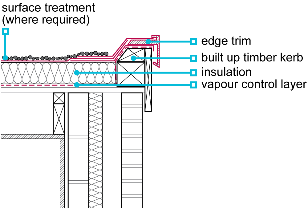
I'm now confused again. I was planning on doing something like below (image from NHBC), but full fill rather than partial fill cavity obviously.
-
Cheers. Good to confirm thoughts; have detailed the warm roof insulation to go over the cavity with an overhang.
-
Main reason for 125mm cavity is aligning to existing walls that will need IWI. However yes can easily tweak cavity size. Given you can get EPS and Bats at same lambda value (0.32) any thoughts on best filler?
-
IWI options on extension and rennovation
mistake_not replied to mistake_not's topic in Heat Insulation
Agreed - actual plan is either 63mm CLS or metal c / I stud. Just drew it badly as 2 bits on the air gap drawing, and didn't correct the non air gap one. -
IWI options on extension and rennovation
mistake_not replied to mistake_not's topic in Heat Insulation
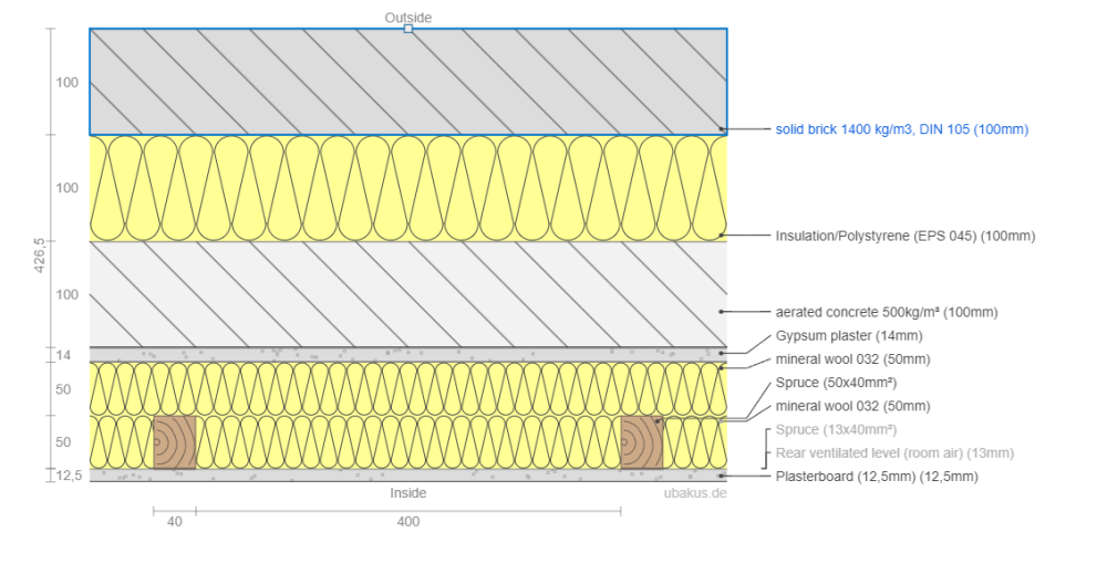
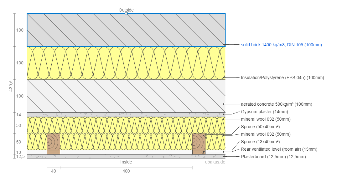
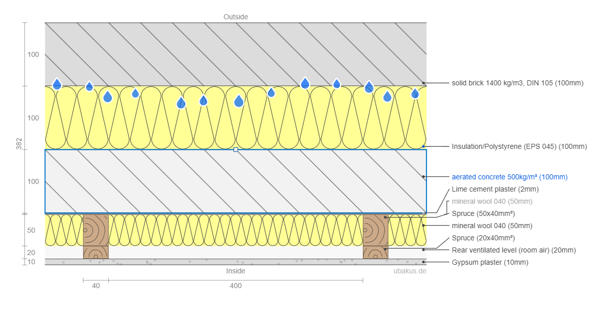
Circling back to this. One final thing I am confused / not sure about: My current plan after advice is to keep the existing plaster for airtightness, adding airtight paint at top and bottom where it is missing / between floors, and tape round windows. Then add mineral wool with no vapour barrier. Material profile below (not airgap size / service cavity size TBC). However, from reading others posts this may have air convection losses with air travelling up in front of the mineral wool as I am not planning to install a vapour barrier / membrane in front of the insulation. Are the losses going to be significant? Or is this not really an issue. This resource suggests I should avoid doing what I am doing: https://www.eurima.org/uploads/files/modules/articles/1607345579_DEF_2020_eurima_howtoinstall.pdf My easy alternative is just to remove the air gap as shown below. But that means electricians have more of a pain running cables / boxes etc, and likely require thicker cables. Thoughts appreciated!
-
So considering options for insulating the cavity of our extension. Have come to the conclusion that using PIR ends badly from an air tightness and gaps perspective. Learnings from this thread: Cavity is currently planned at 125mm and would prefer not to tweak. So thinking my options are: - full fill batts - closed cell foam - EPS In terms of what's easiest for builder not to get wrong, and not need another sub contractor, and VFM full fill batts seems the way to go. However, is there any potential issues with air tightness with using them? To note inner leaf will be parge coated for air tightness and some IWI added (mineral wool) before plasterboard.
-
Nice! Stupid question: surely there is some cold bridging from the upright steel you insulated with aerogel, to this horizontal steel as they are touching? Or is it so many minimal it's best ignored?
-
Did you do anything for the horizontal steel above? (Got a similar set up going in soon).
-
IWI options on extension and rennovation
mistake_not replied to mistake_not's topic in Heat Insulation
Yeah, at same time I'm installing UFH with lots of insulation below. Flow temp at -2 would be 30degrees (ISH). Emitters are too small upstairs for open flow system, so planning on replacing them in 2-3 years then and putting in a heat pump then. For now will mix down the flow for the UFH. -
Where should I put a vapour membrane on IWI
mistake_not replied to thetdog666's topic in Heat Insulation
If you do this then surely you have to breach the VCL multiple times when you run cables / pipes from your service void to your internal face. You want your VCL behind your battens, I'm from of your first layer of insulation (working from inside). -
IWI options on extension and rennovation
mistake_not replied to mistake_not's topic in Heat Insulation
I'm sure you could. 2 different approaches: Estimate and simplify: just add a new source and exhaust on opposite sides of the building, and add estimated flow in and out at each point. External model: model the outside of the building, and see how much air travels through. Bit harder as you have to do temperature as well. However simscale (the platform) I have been using does do thermal modelling with airflow so I'm sure it's possible. -
IWI options on extension and rennovation
mistake_not replied to mistake_not's topic in Heat Insulation
Yup. Complete overkill, but interesting. Takes about an hour to model a house, and then 20 min per run. Been playing with either optimising age of air in the house (low), or creating longest flows through house. Obviously whilst ensuring coverage. Not sure what's best. But, not really needed to just a play thing. Post is here on it: -
IWI options on extension and rennovation
mistake_not replied to mistake_not's topic in Heat Insulation
Cool. Assumed as much. Assume that having the boards run continuously, then studding in front is slightly better, but still not great. Thanks. I'll look properly with WUFI at some point. Good to know the limitations. Super. That's basically my plan. MVHR is planned, just playing with CFD to work out flow etc. -
IWI options on extension and rennovation
mistake_not replied to mistake_not's topic in Heat Insulation
Yeah thought of EWI. I'm in a conservation area so IWI is easier unfortunately. -
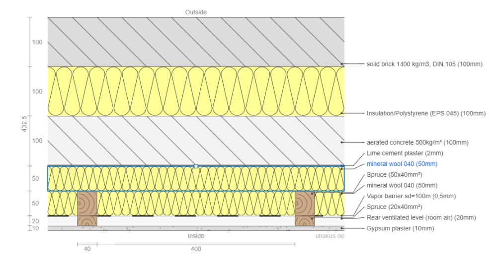
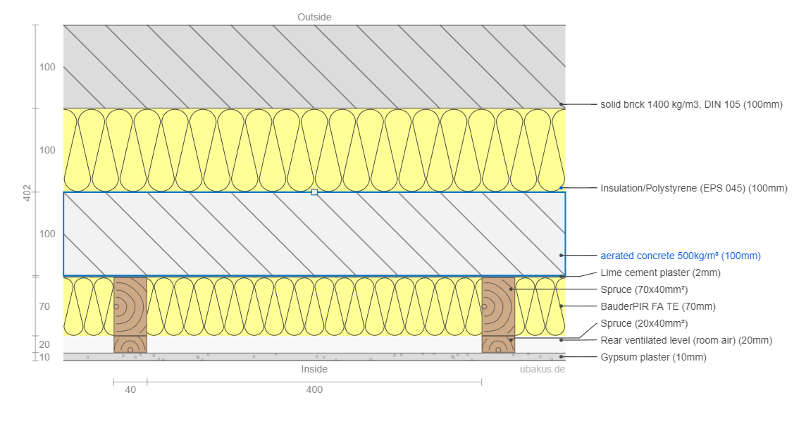
Hi, Been reading a few posts on IWI in the forum, and want to check some thoughts.... We are building an extension, and renovating the existing structure. We are planning on adding IWI during the renovations to the ground floor (upper floor to be done in a couple of years time). Current existing wall build up is: 100 mm brick 100mm filled cavity with EPS 100mm concrete block, partially filled with EPS. From reading others posts it appears that I would be better off insulating with something like mineral wool / wood fibre, rather than using insulated plasterboard. I have modelled both quickly in Ubakus, and whilst the insulated plasterboard shows much lower moisture levels, I assume this is based off perfect fitting of it. Obviously it wont be fitted perfectly, with potential moisture entering at the top and bottom (particularly the top as upper floor not insulated for a couple of years), as well as sockets etc. So, my proposed build up for the renovation is this below. The thickest mineral wool build up ubaqus suggests is 50mm of wool without adding a vapor barrier. If I add a vapor barrier then I think I could increase the thickness of the insulation, as shown below. However, my gut feel is I wont be able to do the barrier well due to brining through existing socket cables etc. To note I am removing all existing plaster from the walls and parge coating with lime as part of the renovation, so I suppose I could re-route electrics then to the service void. Finally, I suppose this is my other option using PIR board between studs, then a service void.... Grateful for thoughts. I am sure I have misunderstood something... Toby


-
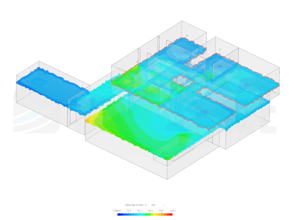
I might have "nerd sniped" myself and done some 3D CAD and CFD.... This run is using the following table for air supply and exhaust: Room Supply m3 Extract m3 kitchen 100 (2 locations) Living room 45 Office 25 WC 30 utility 30 gym 45 family bathroom 30 en suite 30 master bedroom 35 spare bedroom 30 small bedroom 1 20 small bedroom 2 20 total 220 220 Definitely some issues with the CAD, but just playing for now. Not quite sure what I am aiming for though; do I want the longest possible runs between supply and exhaust, best coverage of the whole house with no "dead" zones, or just lowest main air age. Obviously no dead zones seems like a good start point. If folks want to interrogate more you can create your own SimScale account (for free) and copy the project and play (or just look properly at my results): https://www.simscale.com/workbench/?pid=1479988443212465839&mi=run%3A100%2Csimulation%3A99&mt=SIMULATION_RUN
.thumb.png.fb8d6c658afc2f0b9a8613ab08728065.png)
-
I did all this originally. The only bit that was missed was half the kitchen diner, so I added another supply to the kitchen which is shown in the design you see. So specifically, the other 20 comes from the living room, though might pull from office as well. The only element that may not be covered is the stairs.
-
Are those penetrations to allow airflow around a room, or for ducting to go through? I need flow around a room if I was to use a coandra extract (I think).
-
Know of any air flow modelling software? CFD might be overkill! That vent looks good thanks. Annoyingly our kitchen diner will have a steel beam down the middle where the rear wall used to be, which would likely disrupt this approach.
-
All, thanks for the advice so far. To address some of the comments: What would an appropriate supply requirement be for the gym? It does get used (6+ times a week) but only for weight training. My thought is we open a window when training as supplying sufficient air would be hard. Also we keep the gym / utility colder, so keeping supply and extractor from those 2 balanced and therefore eliminating flow to and from the rest of the house seemed to make sense. But yes could easily increase flow and exhaust from those to areas. Otherwise simple airflow modelling has enough going through hall and landing. Also without supply to the kitchen / diner I get no flow through that bit of the kitchen. Agree unit in loft is a pain - even more because I would have to widen the hatch to get it up there. Unfortunately airing cupboard is full, but will see if I could get a sensible ducting run from utility. Anyone got any thoughts on ducting? Specifically is the 90mm semi-rigid ducting worth it?
-
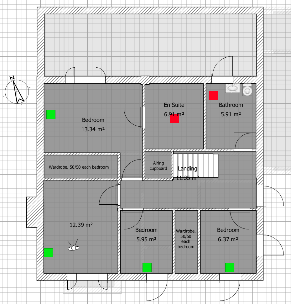
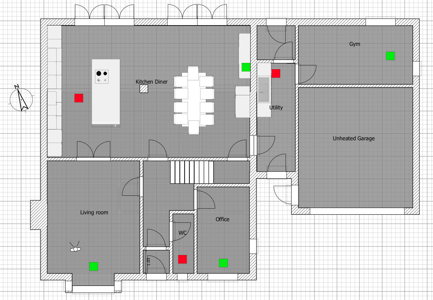
Hi all. Spent a good while reading others posts, and am now planning my own MVHR retrofit installation as part a whole range of works. However, I know I will have missed (at least) one thing, so grateful for a sanity check on my thinking. My current plan is a MVHR unit in the loft, running pipework radially. To help with allergies I want to use a unit that has at least a F7 filter, so was looking at the Zehnder Q350. Quick questions on it: Is it likely to be quieter / less vibration noise if I attach it to a gable wall, or joists? The unit looks good, but should I be looking at something else instead? I plan to use BPC 90mm semi-rigid radial pipe as it seems easy to install, and should provide minimal pressure loss and be quiet. I can drop pipes down to the ground floor relatively easily via some boxing in and use of wardrobe corners. My house layout is as per the two images attached. I have added planned exhaust and supply locations to the diagrams (exhaust in red, supply in green). Total floor areas is approx 190m2. I have the following calculations (from Part L and PassivHouse tables) for amount of air needed, and again welcome folks pointing out the likely errors. Room Supply m3 Extract m3 kitchen 20 67 Living room 47 Office 20 WC 35 utility 29 gym 29 family bathroom 45 en suite 40 master bedroom 40 spare bedroom 20 small bedroom 1 20 small bedroom 2 20 total 216 216 Some very basic pressure loss calculations put the longest and most bendy pipe run at less than 50PA (supply), so think I am fine on that front. Thanks in advance for any that help 🙂


-
Thanks @JohnMo. The Salus actuators look good. Any suggestions on electric mixer / 3 way valves? Have done some googling and haven't found much, the only examples I have found are this: https://www.heatingcontrolsonline.co.uk/ectc-with-sensor.html And this https://www.tiasystem.co.uk/products/manifolds-and-cabinets/mixing-pump-sets/mixing-pump-unitwith-an-electric-actuator,produkt118/ However the simple answer is spec electric actuator/ mixer rather than thermostatic and let the plumber sort....
-
Thanks for the quick reply @ProDave. Yes S plan and different channels and valves is the plan (and existing set up for HW / CH). Questions were more about manual manifolds Vs electronic as well as WC electric mixers. Also my assumption is it's best to have the UFW all running same flow rate. Heat source is boiler but obviously wil likely change to ASHP in the future as boilers go away.... Can't afford to do entire house in one go, hence going to be mixed rads / UFH for a while.
-
Hi, Hoping for some design help / thoughts for a planned UFH installation. I have done some searching/ reading on previous posts but still have questions. The context: I am renovating an extending our house, and looking to install UFH downstairs. We are going to dig up the existing floor slab and lay insulation/ screed so we are not dumping heat into the ground (as well as one other insulating changes). Upstairs will remain as rads, but may convert to UFH in the future, however a few rads will always remain. I have been playing around with loopcad, and looks like I will have 3 or 4 loops of 60ish M. The questions: should I aim for the same flow rates across the loops, same length, or something else? Also should I be looking for a specific manifold/ pump design for mixing rads and UFW? I previously had a single loop on my last house with a very small manifold. I just set the mixer to fully open and used a Tado thermostat with WC to turn it on an off which worked ok, but not great as the PiD control couldn't be set manually so would overshoot. Edit: I am planning single zone and all actuators open: so assume I want the same flow rate on all? Thanks for any help / advice. Toby


.png.5c09d4da7f52613a78343737774b1923.png)