Beelbeebub
-
Posts
1224 -
Joined
-
Last visited
-
Days Won
6
Everything posted by Beelbeebub
-
You also mention the performance is worse on windy days This would point to a potential air tightness issue. If your airtightness is less than designed/estimated then your heat demand will be higher due to more airchanges per hour than expected. Do you have any drafts in windy weather?ie around windows or light fittings?
-
Feels a bit steep.
-
Supposedly British designed and built (I assume with a far eastern compressor). https://ebac.com/heatpumps At least they come in grey and black which will probably look better, or at least less obvious. Interesting slant to the top of the casing which presumably helps shed water in our climate. The only other interesting thing is thry claim a different defrost strategy that reduces the energy lost. It seems (reading between the lines) that at temperatures above 3C but below the critical temp when frost starts to form they simoky don't bother with heating the coil using the compressor in reverse. They (I assume) just run the fan and rely on the fact the frost will melt away naturally in the above freezing air. They also mention that when they do use the reverse cycle they do so at the minimum temperature to melt the ice to water but not to vapourise it. Although the clouds of steam some brands give off during defrost look impressive I don't think they are heating rhe cool up very much, in those conditions it doesn't take very warm water to produce visible steam. But is suppose every little helps. The only downside to this strategy (which tbh I assumed every manufacturer did anyway) is it must be slower than using active heating - so your proportion of heating time to defrost time will be worse and your effective power output lowered.
-
Any thoughts on Adia thermal?
Beelbeebub replied to Beelbeebub's topic in Air Source Heat Pumps (ASHP)
As you say, there are loads of options. But the point is they all require work (and thus time and cost) to fit. By using the almost universally fitted TRV interface, the time to fit becomes negligible. We aren't after perfect, linear flow control. Just flow control that is "good enough" -
Any thoughts on Adia thermal?
Beelbeebub replied to Beelbeebub's topic in Air Source Heat Pumps (ASHP)
I did once try and use a trv valve to control the temperature of an UFH loop. I couod do it manually by moving the pin in and out on a screw thread. But then I tried using one of those thermal actuators and controlling the power to it in order to control the pin location. Turns out trying to control the power to control the temperature of the actuator to control the position when your only feedback was temperature downstream....isn't too smart. 😁 -
Any thoughts on Adia thermal?
Beelbeebub replied to Beelbeebub's topic in Air Source Heat Pumps (ASHP)
One option for the combi replacement is to simply have a 10kw instantaneous heater installed in the "box" maybe with a small (15l is I think the upper limit before you get into G3 regs) hot water tank. Nowhere as efficient but DHW is generally a small component of use. Wire in a 40A spur to the "boiler" which contains a 10kw instantaneous heater in a 15l vessel, plus the pumps and sensors for Adias fancy hub. The HP supply is taken from that box to the outdoor unit. When hot water is demanded the HP shuts down and the immersion heater kicks in. So the wall unit is very much a combi replacement but with an outdoor unit connected through the old flue hole (avoids drilling holes in walls - saves time) -
Any thoughts on Adia thermal?
Beelbeebub replied to Beelbeebub's topic in Air Source Heat Pumps (ASHP)
Yes. Miught be based on the salus auto ones. You need quite accurate positional control which most trv's won't have because thry don't need it. Ultimately a dedicated flow control valve would be a good thing to have rather than bodging the trv interface. Once you have the hardware to monitor individual room performance, you migbt as well male use of it throughout the life of the system. It offers the possibility of the control ability of zoning with the efficency of open loop WC -
Any thoughts on Adia thermal?
Beelbeebub replied to Beelbeebub's topic in Air Source Heat Pumps (ASHP)
Whilst the system can't magic it's way round physics. If your pipe work or rads are too small then there is nothing it can do. What I can see it doijng is getting the absolute best out of your existing system. In a lot of cases that may be enough. At least in the short term. It would be great is the unit could be plumbed into the existing system in advance and then spend a heating season (or even just a few weeks) working out exactly what HP would need, which rads need upgrading etc. The other way I could imagine it working is the unit being designed to replace a gas boiler, ie similar footprint, with the flow return pipes exiting the wall via the existing flue hole (unless it's a roof flue obvs). Then outside a temporary HP can be installed. So you boiler breaks down. You call the installer, who rocks up, sticks this box on the wall instead of your boiler. The outside the dump their "temporary" HP - one probably slightly oversized. They leave the system for a few weeks whilst it works out exactly what is needed. During this time your box is working out what size you HP needs to be, any rads that might need cha gong etc. The running costs at this time migbt be a bit higher than ideal but it's only temporary, akin to using fan heaters whilst your boiler is being replaced. When the results are in, you pick you final HP, maybe a different location etc. Then thr installers rock up, take away their temporary HP to be used on another job, and install your final unit and (if wanted) do any rad upgrades indicated. -
Any thoughts on Adia thermal?
Beelbeebub replied to Beelbeebub's topic in Air Source Heat Pumps (ASHP)
Not quite. Trvs are pretty much on/off. The simply turn rads off when the room.gets too hot. Basically happy shopper room zoning. As I understand it these are used as flow balancers. I assume the balancing valves on the rads will be wound wide open and then these valves will assume that role under the direction of the central brain -
Any thoughts on Adia thermal?
Beelbeebub replied to Beelbeebub's topic in Air Source Heat Pumps (ASHP)
I guess so. But it also decoupled that work from installing the heat generator. Doing it all in one is ideal but does (sometimes) require many days of disruption which may not fit into the owners schedule. It's fine if it's preplanned but for the "shit my boiler has broken down" market that may not be possible and will be a major factor in the heatpump vs boiler decision. Swapping in a new boiler can be done in a day or two No way you could do the MCS route that fast. -
Came across this company/start up. They make a fairly startling claim - to reduce install time by removing the need for changing rads/pipes etc. Behind the slightly unbelievable claim they make some good points.... A large proportion of boiler installs are "distressed" purchases ie boiler breaks down and I need heat and DHW now! For these circumstances there isn't the option of the long lead times for a survey, changing all the rads, ripping up pipes etc. If there is a big saving on install time (via their claimed magic box) there will be a saving on install cost which will offset the higher running costs until the system can be brought up to efficiency. This vaguely aligns with my proposal to use the BUS funds to subsidise the heating costs rather than spending lots of money trying (and often failing) to get the system to break even from day 1. Their secret sauce is basically an automatic system balancing device that will provide the desired room temps for the least flow temp whilst respecting things like cycle times and defrost volumes. It also monitors room by room heatloss and radiator performance to recommend which rads you need to upgrade first. So...... Thoughts? https://www.adiathermal.co.uk/
-
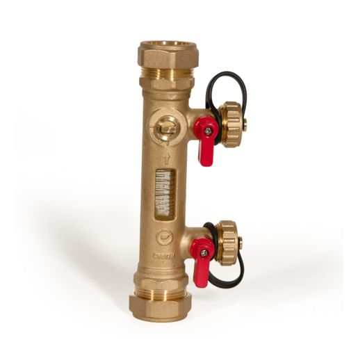
Might be worth getting an old fashioned flow gauge fitted at the same time so you can get a visual indication of thr flow independent of any electronic device. Faulty flow sensors can be a bugger to identify, especially if they are intermittent. With this type of gauge you can confirm if there is a flow or not (plus can see the condition of the fluid)
-
Are we targeting ASHP's at the wrong market?
Beelbeebub replied to ProDave's topic in Air Source Heat Pumps (ASHP)
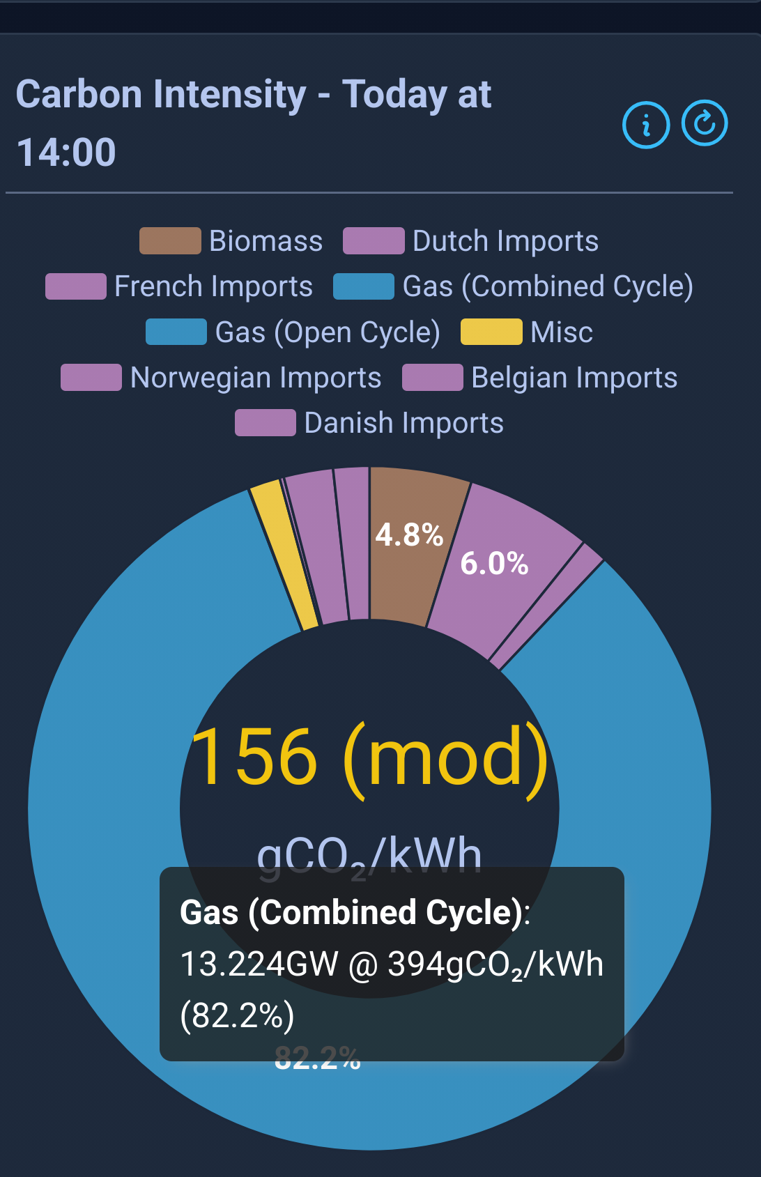
The effect on CCGT efficency of any renewable fluctuations is fairly irrelevant to the "but more co2" argument. In order to produce less CO2 per kwh(t) than a gas boiler, HPs need only hit 2:1 efficency which is almost always the case for UK temperatures. Even for the few days a yer that the HP's might drop below 2:1 and the instantaneous co2 emissions go above those of a gas boiler, the annual efficiency (aka SCOP) of a HP will always be well above 2 (for any reasonably installed system). And the above calculation assumes *all* electricity was produced from gas ie the grid carbon intensity is 400g. In reality the grid intensity is far below that. For example the worst week of 2024 for grid co2 emissions was 220g. So for all of 2024 a resistively heated house produced less carbon than an equivilent gas boiler heated house. -
You're always going to be a bit buggered if the external wall is opposite the heat source. You'll just get a steeper gradient if you up the flow temp. Is there any prospect of moving the rad to the outside wall? Your only other alternative would be some sort of forced air movement - there are fans that are pretty much silent, you don't need alot of air movement to make a big difference. Maybe a large diameter, low speed ceiling fan?
-
Are we targeting ASHP's at the wrong market?
Beelbeebub replied to ProDave's topic in Air Source Heat Pumps (ASHP)
That CO2 per kwh thermal of natural gas is about 200g/kwh. This tallies with around 220g per kwh(thermal) for a 90% efficency boiler. CCGT plants are upwards of 50% efficient at converting thermal energy to electricity. Which tallies with the 400g of CO2 per kwh (electrical). With flow temp of 45c or less most modern HPs can achive better than 2:1 down to well below 0C. Even at 55C flows they achive 2:1 down to -2C There are valid reasons why we can't replace every gas boiler with a HP but "you will increace co2 emissions from electricity by more than you will save by stopping direct burning" isn't one of them. -
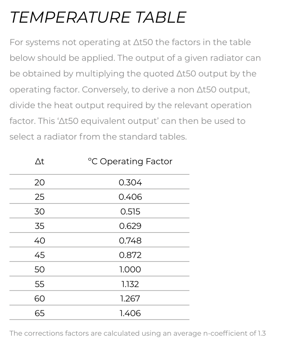
From the stelrad catalog. Remember it's the dT of the mean temp ie DT50 would be something like a flow of 80C and return of 60C (assuming room temp of 20C) So a typical HP with a flow of 45C and return of 40C would be midway between DT20 and dt25 so about 1/3 the rated output.

-
Are we targeting ASHP's at the wrong market?
Beelbeebub replied to ProDave's topic in Air Source Heat Pumps (ASHP)
An efficient gas boiler emits around 220g of CO2 per kwh of heat. A gas power plant emitts just under 400g of CO2 per kwh delivered. So burning gas in a power plant then using an ASHP operating at a Cop of 2:1 would have lower co2/kwh than burning the gas in a domestic boiler. 2:1 CoP is achievable in all but the most ham fisted installation. So if we could snap out fingers and replace every gas boiler with an ASHP (and build some extra gas power stations etc) we would reduce our co2 emissions.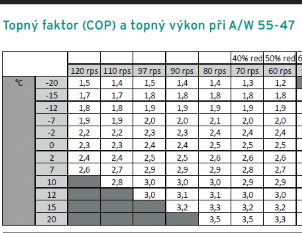

-
Is this the touch screen one?
-
Thats what the auto actuators would sort out. They would regulate the flow so the dt was 7/5C. The alternative is to manually balance the ufh and rads so the dt was to the HP's liking and run it all (ufh and rads) as one big zone. From the HP's point of view there isn't any difference between a rad and a UFH. All it sees is a flow rate at a given pump speed and a dT and will adjust it's power to achive the setpoint temp. If you are hitting the maximum power and are unable to achive the set temp then isn't the problem is your HP is too small?
-
Hang on how is your setup. Is you ufh via a "standard for boilers" manifold with it's own pump and mixing valve? Is your flow and return direct from the HP or. Is there a thermal store/buffer?
-
The lowest flow temp for a given power output is going to be with the ufh and rads both on together (and balanced) because that is the largest emmiter area. So you could run open loop WC, and just balance the UFH and rad flows to give you the best results. What about the salus autobalancing trv/actuators? They monitor the flow and return and adjust the flow (they sit on standard trv valves or even ufh loop actuators) so the dT is 7c (or maybe 5c, I forget)
-
Understood, but is the root problem that there are some rooms that cannot be heated without using rads at 45C and UFH at 40C at the same time? What is the.max temp the UFH can stand?
-
Not scare mongering. *if* the heat exchanger freezes, it's buggered. As you correctly point out, it won't freeze that easily. The only real possibility is a long power cut during a persistent cold snap eg beast from the east (the conditions when the electrical hearing trace won't help) However, in the unlikely event that happens you are onky concerned with draining down the HP. The buried portion prob won't freeze and even if it did it's not that big a disaster. So an AF valve will still provide protection as long as it is positioned to drain out the HP. The rest doesn't matter
-
If you go with an AF valve below the HP but out of the ground - ideally just as the pipe emerges then it should protect your HP should there be an extended power cut and cold spell. Ultimately if your bit of pipe sticking up from the ground to you AF valve freezes it's not that big a deal. The goal is to stop freeze damage to the heat exchanger in the HP. If that freezes you HP is scrap. Even if the pump inside freezes it's not the end of the world, so all you need is thr freeze valves to be such that the HP drains down. I would argue a single one on the lowest outlet (doesn't matter if flow or return) is enough. The goal is to get a flow of water through the HP so it can't freeze solid. If the valve opens and some water flows out that achives the goal. If enough water flows out to empty the HP, that also achieves the goal.
-
S I can get this straight in my head. You want to run in 3 conditions 1) Just rads at WC curve suited to rads 2) Just UFH at WC curve suited to UFH 3) Both rads & UFH with HP outputting WC curve for rads You can currently run 1 & 2 no problem, the issue is with 3 where the UFH circuit drops the return temp so much the HP cannot achive the desired rad temp? Is that correct? Assuming it is, I imagine you essentially have 2 choices. During the overlap time you can either run with Rads WC, and (as you suggest) have a lower flow rate through the UFH such that the return flow/temp doesn't drag the bulk flow down and cause the HP problems. The other option is the inverse, run both at the UFH WC temp. The UFH will be fine (obviously) the rads will be a bit cooler and output a bit less but the return temp shouldn't be an issue for the HP. The downside of this is the rad zones will be a little underpowered but this could be compensated for by switching to rads only for periods to "blip" a bit more heat into the zones. The upside is there shouldn't be any plumbing changes.