


sharpener
-
Posts
1492 -
Joined
-
Last visited
-
Days Won
1
Everything posted by sharpener
-
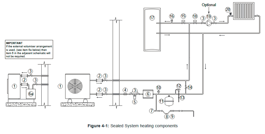
Sorry @JohnMo but it is the same R410a one, the current Grants use R32 though it is not clear what exactly the OP has bought, perhaps he will tell us? <It is normal to have a buffer on the central heating side of the 3 way valve.> Not what the Grant manual shows, [6] is the volumiser in the pic below. If you are going to have one at all then I would think it would still help to have it in circuit for the DHW (as they do). But you could argue that when the CH cuts in you have the extra volume of water at a higher temperature than you want/need/is good for the efficiency. N.b. the pic shows an S-plan setup, this allows both circuits to be in use at once, best not to allow this as the temps you want are very different esp without a blending valve. As others have said this allows for a drop-in boiler replacement in a system with just rads, but the downside is you get far from optimal efficiency with any attached UFH. @JamesPa <wrote Conclusion was that a 5 C temp diff and a 3sq m coil was ok with my planned hp which modulates down to 4kW> So almost certainly OK with the OP's 6kW unit then.
-
Useful stuff @JohnMo but what is the volume of the DHW circuit and how do you stop it short cycling on DHW only? I imagine this is why the Grant manual requires a volumiser under all circumstances. Though AFAICS the Chofu manual does not. (Also it may not be current as I have just noticed it says R410a refrigerant.)
-
How small is a "small" unit? Stick with the min pipe size to match the HP tappings as per the Grant instructions here, which is 3/4 in or 22mm for the smallest. There are also the Chofu instructions here which do show UFH but unlike the diagram on p14 you could omit the blending valve. As @DanDeeimplies this is only required for a boiler flow at ~60C, then you do not need a secondary pump or LLH either. As you will see from the curves on p13 even the 6kW unit has a pump easily able to push 16 l/s against a sizeable pd, actually it can develop a higher pressure than the 10kW. Grant do stipulate using a volumiser, you will still need this to prevent short cycling on DHW only. On p13 they say install it on the flow if it has an auxiliary heater, however on p18 they show it on the return which has lower losses, there are extensive discussions about this on this forum. Good luck, let us know how you get on!
-
That's one of the constraints I'm working with. The previous owners who did the barn conversion built the cyl into a loft void above the airing cupboard in a way that makes it extremely difficult and costly to replace. However from p99 of the installation instructions kindly posted above it looks possible to command the Grant/Chofu HPs to produce DHW by an external contact closure with the thermistor input disabled (p. 97) Can you see any reason why the existing thermostat (or the switch on the S-plan valve) could not do this? This control interface is for me one of the attractions of this particular HP, it is supposedly marketed as a replacement in S-plan boiler systems though I clearly want to optimise its performance as a HP. The other bright spot is that the wiring for this valve is already in place down to the utility room. Although the 4 cores + E could be re-purposed I am not sure whether the tank has a suitable pocket for a thermistor. No I don't know why they didn't just bring the 2 stat wires down and put the valve downstairs where you could get at it but there are a lot of things I would have done differently. Luckily I am ATM still able to get parts for the Kidd boiler even though they have gone out of business, but the former service manager who now holds the stocks is nearing retirement so it is very much on borrowed time.
-
Yes but I see no harm in first giving the HP a chance to do what it can 0300 to 0500. Depending on the siting of the coil vs immersion vs sensor the convection might mix the tank better giving you more stored heat overall.
-
Thanks for that @JoeBano, looks very comprehensive and flexible. After reading that it would seem I could connect it up as follows: 60l buffer tank plumbed as volumiser in return line, or 3 port with secondary pump controlled as "except when DHW activated". Possibility to add 3kW heater as supplementary source in extreme cold conditions. Heating zone 1 UFH on ground floor (four zones, existing room stats used as high limits only, might change living rm to smart starts as only used evenings) Heating zone 2 Radiators on 1st floor. Call for heat from existing Evohome boiler relay. Individual room controls by existing Honeywell wireless TRVs. DHW: exisiting 200l OSO cylinder. Call for heat from existing cyl stat (55C). Use low tariff setting to charge in small hours. Recovery time unimportant as mostly only two occupants, there is also an immersion with solar diverter to boost to 60C as necessary foc. Programming: UFH 24/7 with night setback. Master bedroom first thing and late evening, guest rooms as required. DHW small hours and afternoon boost. No it will never qualify for MCS but plumbing and wiring routes are long and difficult so with a few larger rads this would make the best of my existing infrastructure. TIA for any thoughts on the above.
-
@JoeBano what flow temp do you achieve for the hot water and are you otherwise happy with the Grant 10kW? Do you use their controller, or external/third party controls and what would you recommend in the light of your experience? TIA for your help.
-
Well you imply yourself this is undesirable but see below. If you have a buffer then it is theoretically desirable to maintain the circulation when the HP stops heating to benefit from the stored heat therein. Ditto a volumiser. But if the HP is running for 15 mins in every 20 anyway there is probably not much benefit to be had. Boiler systems almost always have the circulating pump running all the time and manage to be more or less silent. Mine are, apart from 1 rad which gurgles a bit because (I think) it is where the air collects. If yours is unacceptably noisy perhaps it is worth tracking down the cause, air in the system or something partially closed or blocked may be needing attention. Or maybe the pump is turned up too high or knackered or the wrong type for the duty, there are constant-pressure pumps designed to automatically handle widely varying flow volumes which might be better. Bypass valves are adjustable, you would need to set it just a bit higher than the pressure drop required when all the emitters are in circuit, then when the pump stops or other valves close the pressure will only rise slightly and I would expect the HP to handle this OK. Having the volumiser in the return means the losses are lower and there is a good heat reservoir for the defrost cycle. The downside is that this will push cold water into the ch loop - unless of course it is arranged that the ch pump is off during defrost, that is when/why the bypass valve will help. Can you tell us how the ch pump is controlled? Also you have not said if your rads are also controlled by zone valves or TRVs, that would be helpful.
-
No quick fix for this. How is the ch pump controlled, is it from the HP itself or from the system call for heat and can you change it somehow? Is there a programmable run-on setting? Can you wire the ch pump to be on all the relevant time and if necessary put an NRV in parallel with the HP? That's easier, you can put an auto bypass valve across F and R, after the volumiser but before the ch pump. It may be necessary anyway if your rads all have TRVs. That is the layout I am contemplating.
-
Yes but you also need to take account of the declared max running current, the 17.5A represents some 4.2 kW which I presume is the max at startup, your ESS needs to be able to handle this. Victron systems can IIRC supply 200% rated power for 10s, don't know about others. Am considering this Grant 10kW for my own system but plan to connect to grid side of the ESS as it would eat through the 10.65kWh battery pretty quickly. I think the capital cost of thermal storage would be much lower/kWh. Also the 7/35C conditions may not be worst case. I have asked Grant for performance curves covering Ta down to -10 and Tw up to 55C but have had no response.
-
What does your present setup not achieve, and do you need a buffer at all? @IanR's list posted 1750 last Friday seems a good checklist for this. If not then yes, connecting the existing tank as a volumiser in the return line might give an improvement.
-
Octopus ASHP Quotation info
sharpener replied to lakelandfolk's topic in Air Source Heat Pumps (ASHP)
Octopus claim to offer a 7kW "standard installation" for £3k after the BUS grant, worth asking why it is so much more. Apart from the £620 for new rads and an 8kW HP vs 7kW it's not clear what costs the extra £2400. "9 days of engineer time" would surely cover installing the rads as well. Some more information on their pricing from the Octopus web site: "A standard installation includes everything you'd need for a typical 3 bedroom home: Expert no obligation consultation & home survey, A heat pump (up to 7kW) from a leading brand, on a ground level external wall A hot water cylinder (Up to 200L) in the place of your existing one Copper pipe (Up to 12m) and electrical cabling (up to 15m) connected to your existing plumbing and fusebox Up to 9 days of engineer time to install your system System flush, chemicals and magnetic filter to keep your system running smoothly 5 year warranty on parts and labour Every home is unique though so that is why a survey is essential to assess yours.I We’ve been working hard to optimise our processes and supply chain to bring heat pumps to you at the lowest price possible. 90% of our heat pump quotes are lower than the national average of £7,904. Our standard installation costs range from as low as £3000 including the Boiler upgrade scheme (similar to a gas boiler system), when including the £5,000 Boiler Upgrade Scheme grant (which BEIS publish monthly on their website). It can cost more if you have a larger home or non standard installation - we'll let you know if your cost estimate. Find out more about potential additional costs in our FAQs. We'll be able to let you know exactly what you need and how much it costs after your no obligation home survey." -
Hence the traditional siting of the HW tank in the airing cupboard. My grandparents had a completely unlagged galvanised tank with the immersion htr on a peak rate supply. It much have cost a fortune to run but they always said it kept the landing warm(!) But I am not sure that is the intention behind an immersion htr boss on a buffer, it may be more as an auxiliary heater for severely cold weather, some HPs have them integral but some don't. Elsewhere CoolEnergy say you can use it also as the expansion tank, this reduces the capacity to 45l, maybe this explains it.
-
Thanks @IanR that clearly represents some effort on the part of Nibe. AFAIR I have seen this pic before, might have been posted by you in another thread as I searched the Nibe web site yesterday for the internals but couldn't find it. I assume the swept bends are the inlets but for clarity can you confirm which way round the connections are? You can direct flow over quite a long distance - it's an old fallacy that you can direct "suck" to any useful extent but I have often seen pipework details that attempt to achieve it. Agree with @JohnMo less likely to find anything similar at the low end. I will ask CoolEnergy what they have when I talk to them next week, though their 60l tank is very squat to look at.
-
From what I remember of undergraduate fluid dynamics it would seem very unlikely that with radial inlet ports you would get streamline flow in the tank. Then with a low aspect ratio tank the turbulence would ensure pretty thorough mixing. @IanR does mention and post some diagrams that show internal design features which would help, I would be surprised if these are fitted at the bottom of the market but Advance and Trident might, do we know? (I would go for a fish-tail nozzle tangential to the side of the tank and one or more perforated separator plates.) But overall I agree with you, my instinctive approach would be to design (i) so the CH loop pump always runs at a slower rate than the one in the HP, then as of course yr calcs show the balance of flow is downwards through the tank (and self-limiting by the return temp to the HP switching it off when the buffer is full). The converse arrangement (ii) can lead to a situation where the HP is injecting water at its output temp into a circulating CH flow at a lower temp, this mixing is an increase in entropy (again!) which as any fule kno is BAD. I suppose it might be that the mixing that occurs at the start of a heating cycle in (i) above between the cool water from the buffer and the now somewhat warmer water returning from the emitters as the system heats up again is equivalent. But I CBA to do the maths, I think (i) might be better and I very much doubt it is worse.
-
Yes, had followed those discussions but have since investigated one of the most relevant links, this idronics article, a long read but v useful. This says inter alia Buffer tanks connected to heat pumps tend to have minimal temperature stratification. This happens because most heat pumps have recommended flow rates of 3 gpm per ton (12,000 Btu/hr) of capacity. A typical 4-ton air-to-water heat pump operating at these conditions would “turn over” an 80-gallon buffer in less than 7 minutes. Those flow rates, especially if introduced vertically into the tank, create lots of internal mixing. Also I imagine this lack of stratification will be worse in the smaller size buffers e.g. the CoolEnergy 60l one which is almost square i.e. h = w. Some other takeaways are that the 3P configuration is a good compromise giving instant delivery to the load (though for this the shared port has to be on the flow whereas CoolEnergy show it on the return) while having good "engagement" of the buffer. Also the DHW coil feed should be directly from/to the HP not via the buffer. All seems to make a great deal of sense.
-
Thanks again @IanR for spending the time on this writeup. Option 1 is I think a non-starter with the zoning (part of Evohome setup which I want to keep*), there will I hope be times when rooms are up to temp and comparatively little flow. Option 2 is what I hope to get away with, in the return line as you say. The proportional wireless TRVs seem to shut down quite gradually which is good but maybe for a tenner a bypass valve will help to maintain the min flow and prevent cycling. I was supposing that (like a boiler) the HP's internal pump would keep running to circulate even when not inputting any heat, but from what you say it would appear not. If the HP cycles maybe 4 times an hour then the time constant of the rads is probably comparable (and the UFH longer) so perhaps it doesn't matter. But it prompts me to wonder if an external pump would pull the flow through the HX or are there valves that close? In which case an NRV would work as a shunt, I have two spare pumps so marginal cost to try this would be nil. My overall approach would be to design the layout so I can move further down the option table as necessary, fortunately there is space from removing the boiler for 2 x 300l cylinders at least. I originally thought of having two thermal stores/buffers in cascade at different temps but from what I have learnt here it would cost a lot, have a lot of control complexity, be difficult to integrate with what I already have and not in the end give me concomitant savings. Thank you so much for your help. * the house is long and thin; mostly we need rooms at opposite ends heated at different times of day and not much in between except when we have guests
-
Octopus energy launch 'their own' Heat pump
sharpener replied to Post and beam's topic in Air Source Heat Pumps (ASHP)
Maybe Octopus have been following this thread and want to encourage the OP to use his PV to run the HP and then export his surplus. But at least he should be given the choice, it is not very eco-friendly to scrap off new kit that is working satisfactorily. AIUI they are not offering to plumb into his existing coil, it may not be big enough or may not even exist, it is described as a "direct" UV tank. -
I agree about the batteries stealing the PV which was previously available for water heating, and having to increase the amount of PV as a result, because I went through exactly that last year. But IMO it makes absolutely no sense to use the immersion at a time when no PV is available when you could heat the water using the HP for 1/3 the price. I can't believe the cost of the marginal wear on the HP is anything like the difference. I like the worked examples btw @markocosic and agree totally with yr conclusions. I think my Victron system could be programmed using the Node Red option to use the batteries for smoothing out the clouds/kettles etc. but it will have to wait till my HP is installed.
-
Octopus energy launch 'their own' Heat pump
sharpener replied to Post and beam's topic in Air Source Heat Pumps (ASHP)
It's certainly possible from a technical point of view: https://forum.buildhub.org.uk/applications/core/interface/file/attachment.php?id=65234&key=5d7663389b8b5875bb42a43c57211f9d but I do not know if it is either a matter of Octopus policy or an MCS requirement to fit a new HW system. Quite typical overengineering IMHO, I bet the cost is additional to their "standard" installation for £3k. I have asked for an Octopus quotation but they do not have installers in my area yet and I fully expect to end up doing it myself. -
Thanks @IanR, much better informed now. Can you recommend any online resources which go into the design process?
-
Thanks. Have now found yr other thread and agree with you why on earth did they not specify corrected sound power from the HP as 37.7 dB and cut out the Steps 7 to 9 malarkey, they are completely pre-determined and add nothing. The very coarse steps in the distance correction are annoying too, it's not difficult to calculate the distances corresponding to 1 dB increments (many moons ago I used to design recording studio equipment) and rounding the distances down per the table can result in some big jumps. Fortunately the calcs for the Grant or CoolEnergy 10kW machines seem to give a good result for the neighbour's window ~8m away, though the Grant might need a strategically-sited fence panel.
-
The scenario where there are not enough zones open to achieve the minimum flow rate is just the same as for a gas boiler. The pressure drop needed to drive the flow through the heating circuit will also appear across a 3-port buffer and so there will also be a parasitic flow you do not want through the buffer. This flow short-circuits the heating emitters, the flow through them will be less and the delta-T across them will be more. So their mean temp is less, they will emit less heat for a given flow temp from the HP and this is the thermodynamic inefficiency. A bypass valve set a bit higher than the full-bore working pressure drop across the heating circuit will be more efficient for this reason, they are also cheaper and take up less space if you do not need the extra volume. Is it just a custom and practice thing? Or has no-one thought properly about separating the volumiser and bypass functions?
-
Yes I know that is the usual practice. Maybe someone can explain why designers of HP systems prefer to have a buffer or LLH - with their inherent mixing between flow and return, and the loss of efficiency that implies - than a bypass valve which has no mixing.
-
My first thought was the volumiser approach was best, no mixing = no avoidable increase in entropy = no loss of efficiency. I don't think I can get away with no buffer of any kind, we have got rads and extensive zoning which I plan to keep for all sorts of reasons (which you probably won't agree with). Last question: why aren't bypass valves customarily used in HP systems? I haven't found a single example. They would seem to be a better answer than the mixing implied by using a 3- or 4-port buffer tanks or LLH to maintain the flow rate. Gas boilers have had them fitted internally for years.

