LinearPancakes
-
Posts
55 -
Joined
-
Last visited
Everything posted by LinearPancakes
-
Backer boards for large format tiles
LinearPancakes replied to LinearPancakes's topic in Bathrooms, Ensuites & Wetrooms
Many thanks @nod, I'm checking the weight, and good tip about not skimming the tiled areas. Is there anything about larger format tiles generally that would make a cement faced board preferable? Easier to adhere? I'd seen you like to use the BG tile backer board, with a more suitable facing. Would you say tanked moisture boards are about equivalent? Thanks! -
Backer boards for large format tiles
LinearPancakes posted a topic in Bathrooms, Ensuites & Wetrooms
We're having 100x100 porcelain tiles on most of our bathroom walls. They're only 6mm thick though, so hopefully not as weighty as some. Our builder was planning to use moisture board throughout. But our tiler recommended jackoboard for the larger format tiles. After some research, a lot on this forum, it seems like we should be ok with the moisture board as long as we carefully tank the wetter areas, e.g. showers. But I'm not sure if the larger format/porcelain tiles would be better supported/easier to adhere to the cement facings on a board like jackoboard. Cc @Nickfromwales I'm a little reluctant to use XPS based boards as it doesn't seem like they will provide much sound proofing, despite the marketing claims, given the lack of density. In some places we would have tiles on either side of a stud wall, which would seem a particular issue sound-wise. Any advice appreciated! -
Thermal liquid screed pros/cons
LinearPancakes replied to LinearPancakes's topic in Floor Structures
Thanks @JohnMo, that's what I was thinking too. So that leaves the options of Gypsum based liquid screed or Cement based liquid screed (e.g. cemfloor). Anyone got experience of Cemfloor? Any issues with cracking? In principle it seems to have a few extra pros: faster drying, no laitence removal/primer needed for tiles. -
Thermal liquid screed pros/cons
LinearPancakes replied to LinearPancakes's topic in Floor Structures
And by regular I mean regular gypsum based liquid screed. Confirmed this with the company. -
We're looking at 50mm liquid screed for our downstairs so we can still have enough depth of insulation for the underfloor heating to work well. Both regular and thermal (Thermio Plus I believe) liquid screeds are being offered. They market the thermal screed as a way to save energy, but from what I understand, yes it will heat up a bit quicker, but it will also cool down quicker. I'm unsure which option is best, as I suspect the better heat retention/thermal mass could actually be better for getting a nice consistent heat and also for giving options of heating up the screed off-peak, etc. We'll have 9mm porcelain tiles on top which will be adding a good amount of extra thermal mass. Any thoughts on the pros/cons of thermal liquid screed over regular?
-
Vaulted roof insulation condensation risk?
LinearPancakes replied to LinearPancakes's topic in Heat Insulation
Thanks both. @Icevergethat looks like a great tool, wish I'd known about that earlier! Much of this is already set now unfortunately. The PIR between the joists was foil taped to the timbers and to each other to try to make it airtight. With hindsight, if the moisture needs to vent to outside, this was probably a bad thing. Do you think I should ask our contractor to peel the airtight membrane back, slice through the foil tape where reachable then make good the membrane again? -
Should we be worried about condensation on the airtight membrane in the below setup? * Vaulted roof with 200mm deep timbers supporting roof membrane, counter battens and slate tiles * 120mm PIR between the timbers (80mm ventilation void above) (**foil taped to the timbers** which seemed like a good idea, but I'm wondering if it would have been better without since the intello plus membrane allows moisture to pass through) * Airtight membrane underneath (Pro Clima Intello Plus) * 50mm counter battens / PIR below that (inline with each other) * Skimmed plasterboard I believe more typical would be to have the airtightness membrane directly behind the plasterboard, meaning the membrane is at the temperature of the room, so no condensation risk. (And less cold bridging where the timber and counter battens intersect) But that would have meant lighting/power cabling going needlessly through and back out of the airtight membrane, which we wanted to avoid. Hard to know what temperature difference the lower layer of insulation will create between the room and the membrane and whether or not that would be large enough to cause condensation to form. We'll have an MVHR in place, so there shouldn't be too much buildup of humidity. Though I'm wondering it that could actually bring in more humidity from outside in the winter.
-
Whole House Cooling
LinearPancakes replied to sargan's topic in Mechanical Ventilation with Heat Recovery (MVHR)
Yeah, hard to say for sure since the datasheets don't go down that far. -
Whole House Cooling
LinearPancakes replied to sargan's topic in Mechanical Ventilation with Heat Recovery (MVHR)
It will be on the main supply to the whole house. Our home will only be 144m2, so it's way overspecced. A couple of reasons we decided on this: To maximise the cooling output even at lower air volumes. I understand that in the peak of summer, when outside is much hotter than inside, it's generally recommended to keep the MVHR speed lower, since inside will still gradually increase in temperature. I extrapolated, by interpolating the data on the datasheet, that the CW12 should deliver ~3kW cooling even at ~100 m3/h. The CW6 for example could only achieve ~1.6kW. Chart attached. The reduce air resistance, both when not actively cooling but also when cooling as the air resistance increases a lot then, presumably due to condensation internally. The CW12 should have a negligible air resistance of ~7Pa when cooling at a boost of 240m3/h. The CW6 comes in at ~33Pa for that. (Caveat, all theory so far!)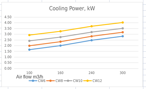
-
Whole House Cooling
LinearPancakes replied to sargan's topic in Mechanical Ventilation with Heat Recovery (MVHR)
Thanks, hopefully it'll do the trick. We've designed it ourselves. It's a radial system but using steel ducting. Using the matching Zehnder manifolds to minimise any crosstalk. The idea is that the thinner duct wall means more space for airflow/insulation. Also lets us increase the diameter where possible. It's a *lot* more work though and definitely the path less trodden! -
Whole House Cooling
LinearPancakes replied to sargan's topic in Mechanical Ventilation with Heat Recovery (MVHR)
We're soon to install an oversized Zehnder CW12 duct cooler in the supply, taking a feed from the reversible ASHP. All supply ducting will be well insulated and has been optimised for low air resistance so we can potentially increase the fan speed if needed without too much extra noise. Not expecting huge cooling power, but if it can discretely drop a few degrees across habitable spaces we'll consider it a win. We've also made sure to have external blinds/solar control glazing on the south elevation, but don't want to risk that alone being enough. I'll report back on how it performs next summer. 😅 -
We're looking at using the Lindab VHL and VHA roof terminals for supply & extract respectively. The MVHR unit will be located in cold loft space right underneath where the terminals will go, so only short runs needed for intake/exhaust to outdoors. Most of the time the loft should be a similar temperature to outdoors, but probably getting hotter in summer. Based on previous advice we're looking to insulate those runs anyway, I guess primarily to avoid heating of the supply air, rather than to avoid condensation. What I'm wondering is, is there much point having insulated pipe continuing through the roof transition to outside. I can see the benefit if you've got a warm loft, as you don't want the cold bridge and associated condensation risk. But if the loft is usually the same temperature-ish, is it worth it? I'd prefer to have the smallest hole through the roof we can get. Lindab diagram below. Specifically we're talking about a 160mm duct from the unit and possibly up to a 280mm diameter transition piece if we went for their SRIP, that does also handily match the terminal diameter. Thank you!
-
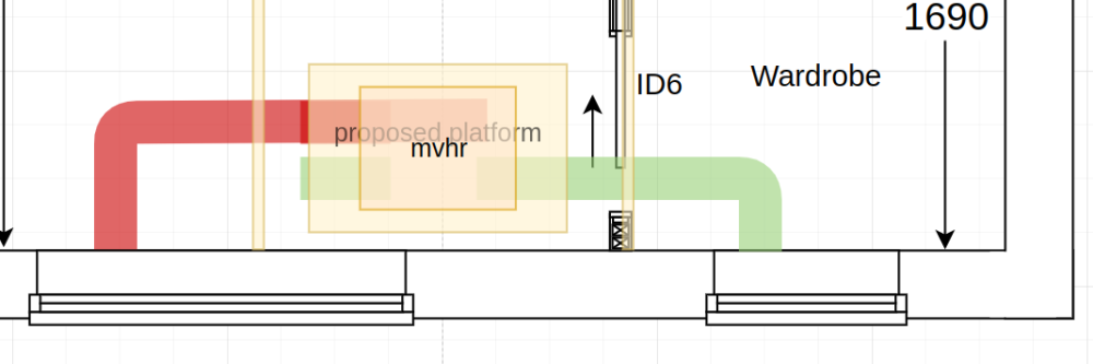
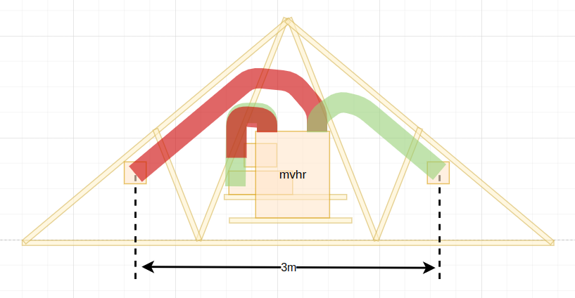
Many thanks for the feedback. That's why I find myself keeping coming back here, such a melting pot of knowledge that has been put into practise. I'd seen the combi grilles. They'd be a good option, but the gable wall available is at the front of the [brick] house and would stand out a lot. I'm currently leaning to using the gable wall using more low profile separate intake/exhaust. Any thoughts on this arrangement for the unit & terminals? Our loft is a cold loft, so will be insulating all the things. Airtightness layer underneath the joists. I was originally trying to keep the duct runs to the terminals going upwards, to minimise condensation draining from the terminal. But seeing that others have them going down to the terminals as well, I wondered if it would be that much of a problem in practise. Running them this way allows them to be roughly 3m apart, and sheltered under the eaves to reduce rain/wind. Rytons look to have nice brick sized terminals, with a range of grilles for low resistance, that could be colour matched. I'll have to call them and see if they can do one with a 160mm dia round duct on the back to avoid limiting airflow. (MVHR unit has 160mm internal dia)
-
Wow, many thanks @Iceverge, great that there's some data available on this. What was the source? Disappointing that the manufacturer chose to showcase their product being used in a bad practise installation. I saw another promotional material the other day where the terminals were around the corner of the house from each other. It gets me thinking about what is optimal here. Probably the same type of terminal is also important. Different types of terminal, in additional to having different air resistance generally (which I expect you could balance out), might be more susceptible to wind than the other, e.g. something like this might also be hard to balance: https://www.ventilationland.co.uk/product/15660/thermoduct-flat-horizontal-roof-terminal-diameter-180-for-sloping-roof.html
-
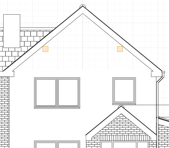
We're in the process of, for better or worse, self-designing our MVHR system and currently looking at the terminals to outside. I understand that it's best to keep extract & supply on the same elevation to avoid pressure imbalances caused by the weather. However it would work well for us if we can put the terminals either side of the ridge, a bit like in the image on the Ubbink website here: https://www.ubbink.com/int/products/ventilation/terminals-and-seals/roof-terminals/ventus-roof-terminal-200-180-pitched-roof/#specifications They'd be 1.5m apart, to plan, and they'd be pretty close to the top of the ridge anyway (maybe the top of the vents 30cm or so below the ridge), so I'm wondering if this is going to be that imbalanced in practise? The roof would likely shelter one of the vents from prevailing wind a bit more than the other. Thanks!
-
Thanks @JohnMo, that's what I was missing, you use the maximum.
-
So I've pretty much decided to DIY our MVHR install using a radial system. I'm also having a go at designing it, but am not sure how to calculate the total static pressure of the system, so I can make sure it's not working too hard. The passive huas trust indicates it should be <100 Pa ideally. I get the general idea of pressure drops, and how to work out the pressure drop of an individual run. You sum the pressure drop from each component in the run, bends, ducts, attenuators, at the correct diameters & lengths. And I'm pretty sure you need to add the pressure drops from both sides of the supply/extract. (So outside->mvhr + mvhr->inside + inside->mvhr + mvhr->outside) But what I don't understand is how the pressure drops of the multiple runs from the manifold, each with different lengths and bends, should be combined to a total static pressure for mvhr->inside and for inside->mvhr. Can someone help plug the gap in my understanding?
-
Thanks @Jimbouk. I'm currently looking at the Vent Axia Plus B. It's a little oversized for our needs, which I'm hoping will help. Also considering the Zehnder Q350 as it has 96% heat recovery, compared with 91% for the Plus B. But it's more expensive, physically bigger and 2x the weight.. 🤔
-
Hey @Jimbouk, I'm looking at the same unit with the same ponderings. Did you purchase the Advance SX in the end? Keen to hear your experiences if you did.
-
100x100 porcelain tiles, 6mm thickness
LinearPancakes replied to LinearPancakes's topic in Floor Tiles & Tiling
Many thanks Nick, that's what I thought. We'll try to seek out a style we like that's 9mm or more for peace of mind. -
We've found some porcelain tiles that we really like. They're 100x100cm but only 6mm thick for the inside. All of the other porcelain tiles we've seen have been 9-10mm thick. Is this thick enough? Feels like it might increase the chance of cracking if something dropped on it.
-
Thanks for the advice folks. We've got a plan to try to avoid crossing the steels by dropping the ducting down at different points from the loft. (It's a cold loft so we'll be insulating the ducting up there and making an insulated "box" the unit can run in.) But it's good to know that the change in shape is viable should we need to do it. Also discussed with our contractor and it's possible to add holes in the steels post fabrication/install too, obviously with advice from structural engineer about placement and any re-enforcement needed. So we have plans A, B and C. Interesting about the resistance from flexi ducting generally @saveasteading. We were planning to use e.g. 75mm semi-rigid ducting in an "octopus" arrangement. Would the additional air resistance mostly come from the bends in the flexi pipes, the ribbed surface of them or there being more pipe surface to volume of air moved in the octopus arrangement (vs branched), do you think? Distances shouldn't be too long as it's a fairly compact 3-bed home.
-
In our refurb we're using 219mm easi joists throughout, which gives plenty of space internally for 75mm semi-rigid ducting. However we've a few steels that we will probably need to cross. We'd assume the remaining space above the steel was going to be about 60mm - enough if we used oval ducting instead, either adapting when crossing the steel, or just using oval ducting throughout. But it turns out that for a few steels this is going to be more like 30mm. Is it OK to adapt the round/oval ducting to e.g. a 30x147mm rectangle with the same area, or is the change of shape going to create too much air-resistance/noise?
-
Dekton/Neolith shower partition wall
LinearPancakes replied to LinearPancakes's topic in Bathrooms, Ensuites & Wetrooms
Thanks Nick, I think you're right. Glass there may even be nicer and a lot easier. -
Dekton/Neolith shower partition wall
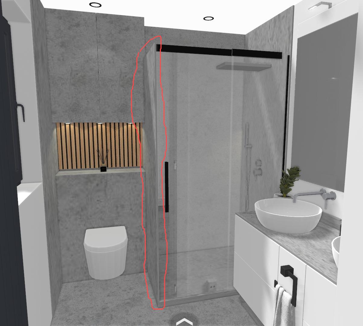
LinearPancakes posted a topic in Bathrooms, Ensuites & Wetrooms
We're designing our new ensuite and it's a pretty compact space. We'd like to have the shower enclosure be glass only on the front, rather than on the side as well. But given the dimensions, we don't have the space for a tiled stud wall to the side. Given shower enclosures are made of tempered glass, I'm wondering if it's that much of a stretch to use a sintered stone on one side as a partition. For example, say 20mm Dekton, which would be around 80x200cm. Obviously this would be heavier than <10mm glass, but it looked about the same weight as glass by volume, so maybe only 2x as much. We can double up joists if needed to support it. I've not found any examples of this being done though. Do you think this would be possible/permitted by b/c?