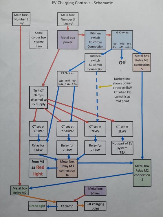
PV EV charger control schematic
This is the latest system we have:
There are 4 CT relay clamps, 3 for the EV charging, (and one will be for battery charging), which are set at different PV output levels depending on the month of the year which decides what rate of PV needs to turn on the charging of the EV. This relates to a 3kW charger and the expected power requirement for the EV on a particular month and the expected production using the PGIS web site calculator.
The summer 3.6kW rate is because the house typically uses about 0.6kW and during the summer there are plenty of hours when the power is over 3.6kW.
There is of course an override for when we will charge irrespective of the PV supply.
When the mains option is chosen a red light indicates this choice.
When the car is being powered the green light indicates this.
The theoretical result is not as good as I hoped as M2 relay is time delayed to stop the charging going on/off quickly during cloudy/sunny days, and because of the lack of supply during deep winter, however for 4000miles we hope to use about 730kWh PV and buy 70kWh from the mains.
This will improve if we manage to obtain a bigger power storage EV as the PV history for hear over the last 15 years shows good days are usually grouped together meaning during winter we might not have used up the power in EV before another glorious day comes around and then have a week of cloudy weather.
The only works because the car is plugged in to the EV charger most of the day time. (like today).
I'm hoping someone can use this to help them develop a similar system.
If you need any info on the parts are, ask.
Good luck
Marvin


3 Comments
Recommended Comments
Create an account or sign in to comment
You need to be a member in order to leave a comment
Create an account
Sign up for a new account in our community. It's easy!
Register a new accountSign in
Already have an account? Sign in here.
Sign In Now