Search the Community
Showing results for tags 'acrows'.
-
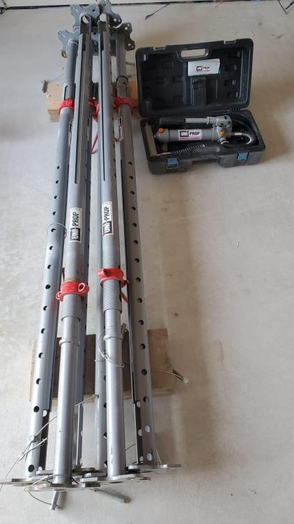
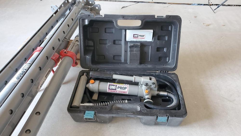
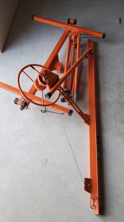
We ate now done with the heavy work and have some gently used equipment for sale. 1. These structural jacking posts are vastly superior to acrow props. They have a hydraulic jack so can be used gently and precisely to support or even lift joists etc. No more bashing the screw with a hammer. Equally importantly they release gently. They were barely used as I instructed their pirchase to support a very dodgy area of the old building, but we knocked it down instead. Very suitable for self builders. I would not have bought them for a commercial project as they would have disappeared. 2. Plasterboard hoist. For lifting and holding plasterboard up to 16ft, into place until fixed. Can deliver between Inverness and Gloucester A9 and M6 / M5 when passing in a couple of weeks.
- 9 replies
-
- acrows
- acrow props
-
(and 2 more)
Tagged with:
-
Acrow props – is there an alternative that won’t fall down? Yes there is in some cases. Much depends on your programme, whether you wish to give it a go yourself and how much time you have on your hands. Please feel free to comment / question. I’ll answer if I can (if not, I hope some other BH members will be able to) and provide more detail. Photo 07 showing holes for the needles and the first few temporary works studs going in. The base of the studs are sitting on a sole plate fixed down to a temporary strip foundation. Part of the sub floor has been built up and concreted to provide a working platform. Photo 04 (copied from previous post) In my case I have been dipping in and out of our project. I reckoned that I would need some 25 – 30 Acrow props for the temporary works which would take me about 4- 6 months as I was also mucking about with other bits of the build. To hire 25 props at £ 5.00 per week = £ 125 per week! I could have bought the props but I would have needed to get rid of them after in my case, just gave up on that. I have two or three old props that were used to help tighten up (pre load / stress) the timber propping. The timbers 145 x 45 (grade C24) to form the needles studs, top and bottom sole cost ~ £350.00 ex vat plus a few screws (about 250 number 5 x 80 gold screws I think) to fix things together. I knew that I could recycle the temporary studs to form a new floor we needed and that if I cut back the needles I could also use these to prevent the top steels from moving sideways. This is called simplistically “ lateral restraint”. Also, I used same needles to provide additional what is called “torsional” restraint to the top beam , a slightly different effect, but is it to do with the fact that I used one beam with a top plate to support both the inner and out leaf of masonry which can be loaded in different ways at different times. These different loading patterns cause an uneven loading on the top of a single beam.. resulting in a twisting (torsional) effect. You can see more photos in post 01. Fig A 01 showing proposed rear elevation. How does it work / stay up? The starting point here is to calculate the amount of load. With this house the roof spans front to rear, the attic is full of stuff, the walls are rendered brick cavity walls and you have part of the weight of the new extension roof that is now attached / built into the outer leaf of the house. Once you calculate this you end up with a working load you need to hold up of round about 25 kN/m run of wall. Approximately 1.0 kN (kilo Newton) is ~ 100kg so 25kN/m is about 2.5 tonnes per metre run of wall. Thus if you put your needles at 600mm centres then each cluster of needles has to carry 0.6 x 25 = 15 kN (1.5 tonnes) and the studs supporting the needles at each end need to carry a vertical load of roughly 0.5 x 15 = 7.5 kN (0.75 tonnes). These types of loadings are as about as much as you can “do” for this type of system. There are other ways but you need more height for timber needles. To make life a bit more difficult the window lintels on the first floor cause the load from the roof to be unevenly distributed so some needles need to carry more load than others. You can see from the photos that some needles are in pairs, some are a cluster of three. In terms of the studs these needed doubling up in places and the whole lot horizontally braced at mid height with some diagonal bracing just to stiffen the whole lot up. While this sounds like a lot of work once you get going it’s actually quite quick. This approach is a little different from using Acrow props. With Acrows you wind up the prop to preload the system so that the upwards force is approximately equal to load the wall you are taking away is carrying. Aside, If you are Acrow propping things then be careful not to over tighten the props as you can easily start to lift parts of the house accidentally! Here, what I did was to use a combination of the spare props I had combined with timber wedges to pre stress the system, one set of needles at a time. The other thing is that over time the timber can shrink / creep a bit so I was careful to get the timber dry first and then monitor the system as I went along. All sounds complicated but once you grasp the principles a lot of it is common sense and this is not a reinvention of the wheel. I know a few old joiners and brickies that still remember doing this when they were serving their time. Some extra information that may help. As always, comments welcome. Options for beams- In terms of material vs labour cost it can sometimes be beneficial to design the steel beam as a single beam with top plate. The one you see here forms part of a double flat portal frame. You will also see designs that use a separate frame for the inner and outer leaf, a question of balance, each project is different. You can introduce a problematic thermal bridge at times if you deploy these single portal principles to an external wall, but in my case the steels are now internal.. the thermal bridging is resolved in the main. Propping considerations. Below is a screen shot of part of a temporary propping design for a set of 4.0m bifold doors etc. There was another big chunk of the rear wall to come away at the same time which is not shown. The contractor here was stopped from working until remedial action was implemented. Screenshot propping.docx Fig 02: The purple lines are the props and what is called the lacing / bracing system to stop sideways movement. Work was stopped when this was discovered. Part of the contractor’s defence was that “he was insured” Photo 08 Photo 09 A few points. The Contractor had not investigated the ground under the slab and the base of props can slide about. The site investigation had revealed this ground was very soft. Use of Strong Boy type supports at the head of the props.. these have a reduced load capacity and not suitable for the loads to be carried in this case. Props well out of plumb, no bracing.. further comments welcome. On a finishing note the timber propping scheme may look a bit rough but it was designed and executed with no unexpected movement. If this approach may suit you then as always check with or be a competent person. Thanks for reading.
-
ooo 203x203x86 6 meters long best practice for shawing up existing building im finking about bying a brick brace set nock down wall support steel install padstone does this method sound ok finaly my rsj is grey primerd shall i red oxide them cheers everyboddy your opinions have been invaluable thamks
- 10 replies
-
- acrows
- brick brace
-
(and 2 more)
Tagged with:


