SBMS
-
Posts
1071 -
Joined
-
Last visited
Everything posted by SBMS
-
Is it enough? He’s done the storm calculations and says it is - that’s what we are paying him for, so got to assume that his climate adjusted 1 In 100 year storm figures are correct? One thing I have noticed is some engineers count the driveways (even if permeable) into modelling/attenuation figures and some don’t - did yours (assuming your driveway areas are permeable?)
-
Thanks @Dave Jones - I spoke with the engineer today after these comments and he basically said we could go with either. He pointed me at some manufacturers of plastic manholes that were cheaper but fundamentally said we need 4m3 of attenuation with a hydrobrake and said we could use crates or a manhole. He suggested speaking to our groundworkers to price up the most cost effective route. Seems like a pragmatic response at least.
-
It was over engineered. Our house was one of 3 self builds at the site and we inherited the scheme that had been approved and discharged with the council. The owners of the site had responsibility for implementing the scheme. Our builders, the ground workers and another drainage engineer I asked to have a look at it said it was entirely unnecessary and some crates would have sufficed. Fundamentally 500 sqm of driveway was used as attenuation. This was dug down, lined with membrane and then filled with stone with a hydrobrake at the end to discharge. Ironically it was an absolute silty mud pit by the end of the build when the crates went down and likely totally impermeable below the crates. In any event… Agree with your comments on the chamber, seems really expensive way to do it
-
Ah okay - that gets a bit closer then - a set of attenuation tanks to do 3.5m3 (the 2100mm chamber option) is about £500...so it might be a wash price wise or a few £100 more? Do you think the 'ease' of install balances the slight increase in materials (saving on labour costs for digging two holes for example?)
-
Editing my previous message… I was thinking of the radius not diameter so got you re the 2m2 of crates. Do sokeaway crates do the same job as a manhole?
-
We’ve had our SUDS compliant drainage plan designed by our engineer. Compacted clay so no chance of soakaways etc. I had asked to minimise attenuation tanks etc - to be compliant the engineer has designed for water to be attenuated in the surface water pipe work and oversized manholes. The big one is a 2100mm diameter by 1m deep manhole with a hydro brake limiting to 2.6l. This will run off into a distant stream (via an existing drain). I’ve looked online at the concrete ring which is about £900 so not obscenely expensive. our last build was eye wateringly over engineered to the point of having the entire driveway effectively be the attenuation system with layers of stone, membrane and then crates on top. Very expensive. The manhole above looks like it’s about £900 so seemingly not too bad. Has anyone put something like this in before? It’s been sited in what will be the garden - how much of it has to be exposed? The full 2.1m, or can it be turfed over (or partially turfed over)?
-
What’s the umbrella company called?
-
Thanks @JohnMo, a fair point. I'll ask the floor engineer to design to minimum depth, based on the SE arrangement and then increase as needed. My question was really, if the floor manufacturer can do a 202mm does this even work for services.
-
We're looking at specifying our posi joists for our intermediate floors. For a number of reasons )mainly head height) we want to specify the minimum depth joist we can. The posi joists we're looking at have the following minimum clearance depths between the flanges: 108mm 131mm 159mm We'll be using flexible MVHR ductwork which should be fine with any of these. I think our biggest service will be any 4" soil pipes with bends etc. What would be the minimum recommended depth for this?
-
Thanks @Mr Punter what’s an intermediate pitched roof? We were looking at blown cellulose - what would you recommend?
-
Thanks. Why would you not advise mixing PIR on top and Rockwool in between? also - what are your thoughts on warm roof for pitched roof?
-
Can we also fill between the rafters with Rockwool or PIR?
-
Good question, we are only at draft stage and I know the architect has a detailing for it. However I am inclined to agree that a warm roof is looking like a better option. am I right in thinking there is no ventilation requirement for a warm roof? Is there anything stopping us putting Rockwool between the flat roof joists as well to further lower the u value? I am wondering about whether to abandon the idea of cellulose on the pitcher vaulted roof as well if so and go for a warm roof there too..
-
Thanks @ADLIan I can see your point especially with the wall junction. What would one typically recommmend as a makeup to achieve a circa 0.12 u value? Can you insulate between the joists with rockwool and then above with PIR for a warm roof?
-
Sorry, I see what you’re saying. Architect has specified 50mm ventilated cavity above the insulation and below the final roof deck.
-
Why can’t the flat roof joist void be fully filled with insulation?
-
We are doing a cellulose full fill so we shouldn’t need a ventilation cavity as long as use a breathable membrane. You’re correct, the beam is on steel columns down to foundations.
-
Having re-read my question... is my steel beam entirely within the thermal envelope? Am I worrying over nothing?
-
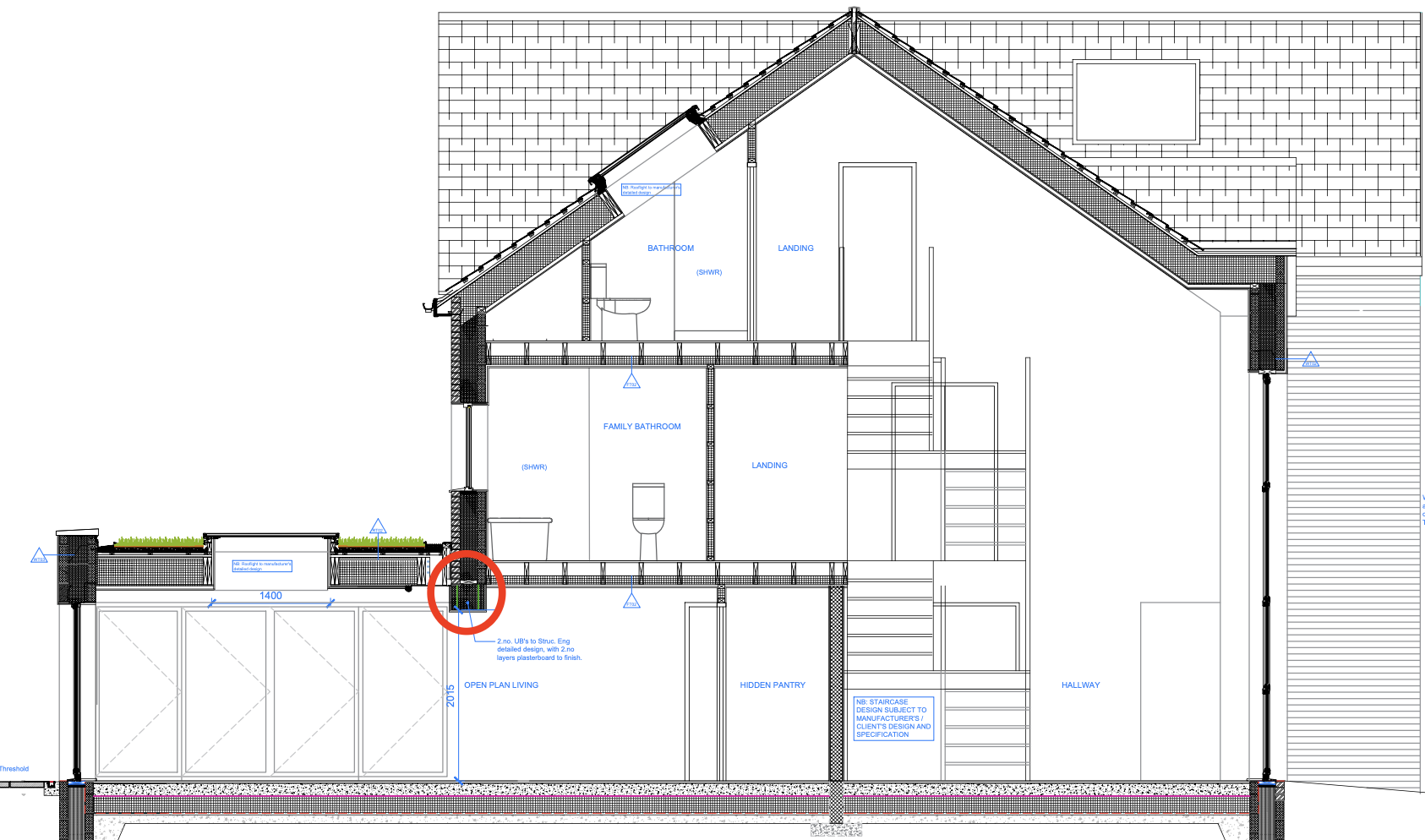
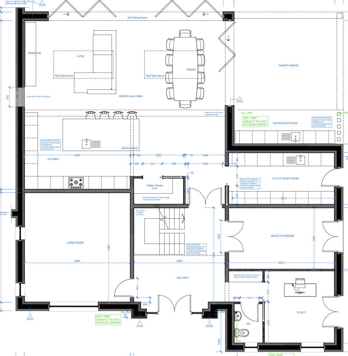
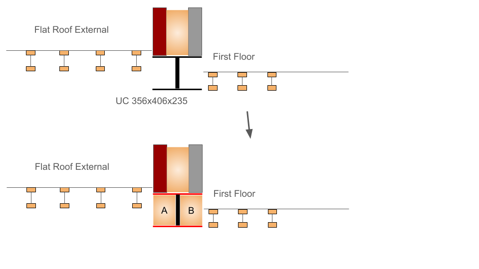
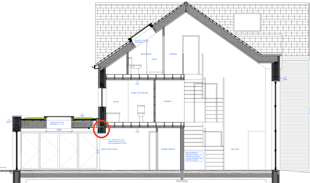
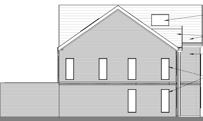
Hi all Will be speaking to our architect to get advice, but he's away at the moment and keen to understand what's possible. We've designed something which requires a fairly large steel to carry the rear of the house where a single story flat roof intersects at the rear. The smallest height steel we can get is a UC 356x406x235 - spanning about 10meters. To minimise any boxing in, in the kitchen, we are looking at moving this steel as far up as we can - ideally level with the bottom of the first floor joists. I'm trying to understand how we insulate the steel and prevent as much thermal bridging. I've drawn a crude diagram of our ideal profile of this beam. Our cavity is 200mm and the beam is just under 400mm wide so we can presumably pack some insulation into the face of the beam as shown in A and B below. I assume that we won't be able to do this where the first floor joists run into the beam, and also the top and bottom flange marked in red: Are there any other options? Rear elevation of the house, floorplan, and section drawing with the beam marked in red:

-
We’ve got windows that range from 2300x1300 to 600x1660 So It’s a bit tricky to post particulars @G and J as we’ve got all sorts of different size windows, I was just wondering if there’s a rough formula? You can end up obsessing about u values…
-
Does anyone know if there is a general rule of thumb for how the u value of the glazing unit affects the overall window u value. This is just for some rough calculations whilst doing some cost benefit analysis for different windows. In particular, say that a windows total u value is 1.4 based on a window u value of 1.0. If that window was changed for a triple glazed unit with a u value of 0.6, what might one expect the total u value to decrease to? My simple logic (probably wrong) makes me think that as proportionally the majority of the surface area of the window is glass, the majority of this 0.4 reduction in u value is conferred across the whole unit, possibly bringing it down to 1.0 overall u value. The bigger the window, the more pronounced this might be. Is this in any way correct, is there a way to approximate how lower u values of glazing might affect the overall frame u value?
-
The first option is interesting - the staggered timbers looks good for thermal bridging. How would you go about connecting the 97x45mm To the 220s above?
-
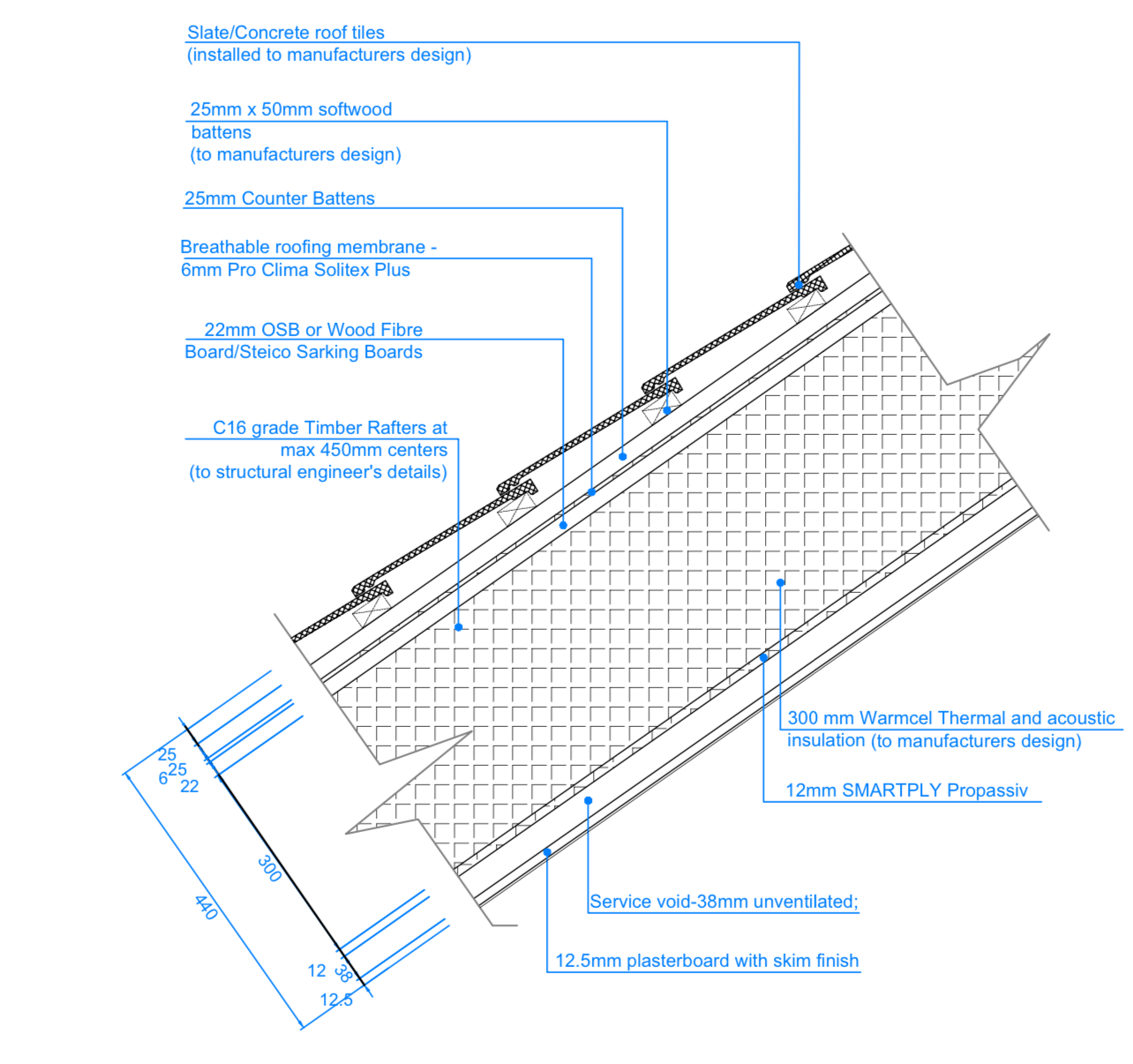
Hi @Iceverge I have attached full roof makeup showing depth below. I suppose I felt that 0.1 would be a great target and so every point I move away from that is psychologically difficult! But your logic makes sense.

-
I wonder whether the valleys and complexity of our roof are making blown cellulose a difficult or suboptimal option? I keep trying to work out whether there are going to be a lot of ‘nooks and crannies’ to fill with cellulose?
-
Posted a section.