Ultima357
-
Posts
111 -
Joined
-
Last visited
Everything posted by Ultima357
-
Heatmiser Neostat v2 temperature sensor problem
Ultima357 replied to Ultima357's topic in Underfloor Heating
You can calibrate the Neostat within the options menu to read the same. I used a reference calibrated thermometer to set mine up. -
Heatmiser Neostat v2 temperature sensor problem
Ultima357 replied to Ultima357's topic in Underfloor Heating
An answer from Heatmiser :- The thermostats use a rolling average with an artificial temperature limit of 0.1 degree rise(or fall ) every 10 seconds. if you power the device down the rolling average is lost and the device starts with an average value of 0 there are 16 readings taken each time so the average quickly rises, the process then continues until it reaches equilibrium. So its not surprising that you saw a lower temperature just after powering the device on. The headless device remain powered so didn't lose its rolling average when the system was powered down. There is a second temperature sensor in the middle of the powered unit that monitors the power supply temperature, predicts the effect on the room sensor and compensates in real time. Its not perfect but has been tested repeatedly in an environmental chamber whilst mounted on a plaster board frame with and without wall insulated behind the plaster board. The test results show that the measured temperature matches the chamber temperature within the specified +/- 1 degree or better. I've pointed out as I did originally, that it is a building regulations requirement for noise reduction insulation to be fitted in stud walls and suggested they retest with insulation. 🤔 -
Heatmiser Neostat v2 temperature sensor problem
Ultima357 replied to Ultima357's topic in Underfloor Heating
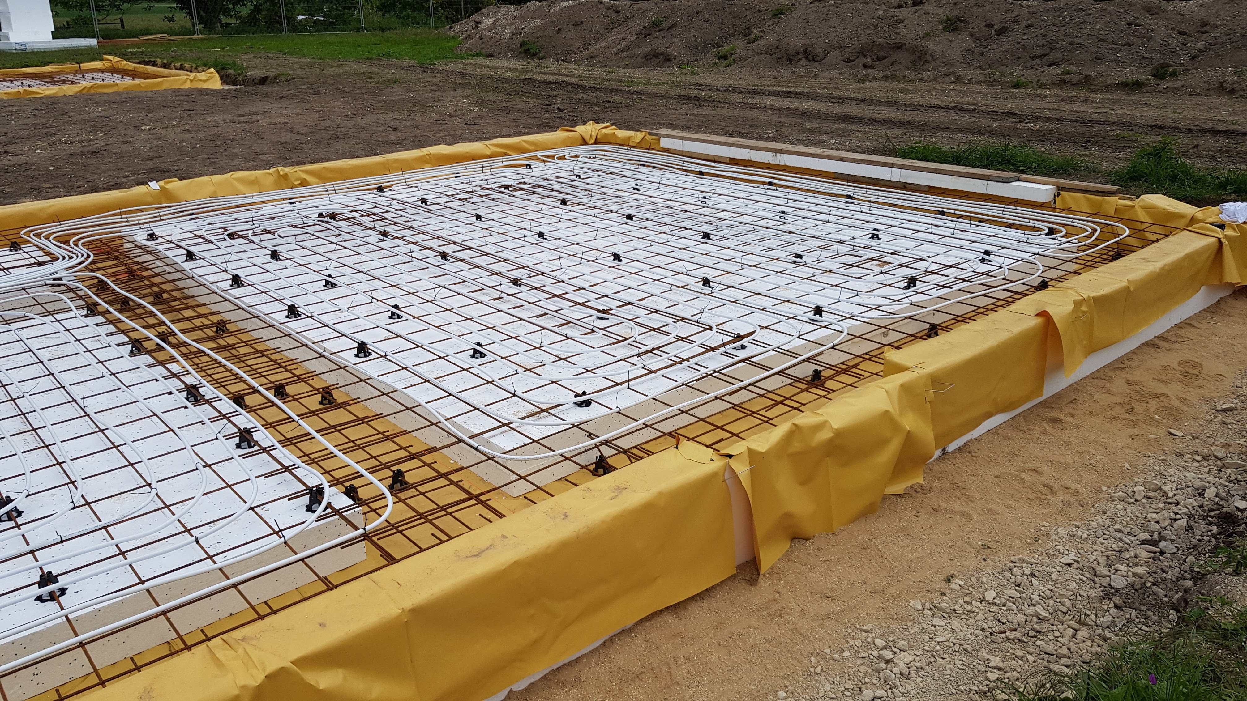
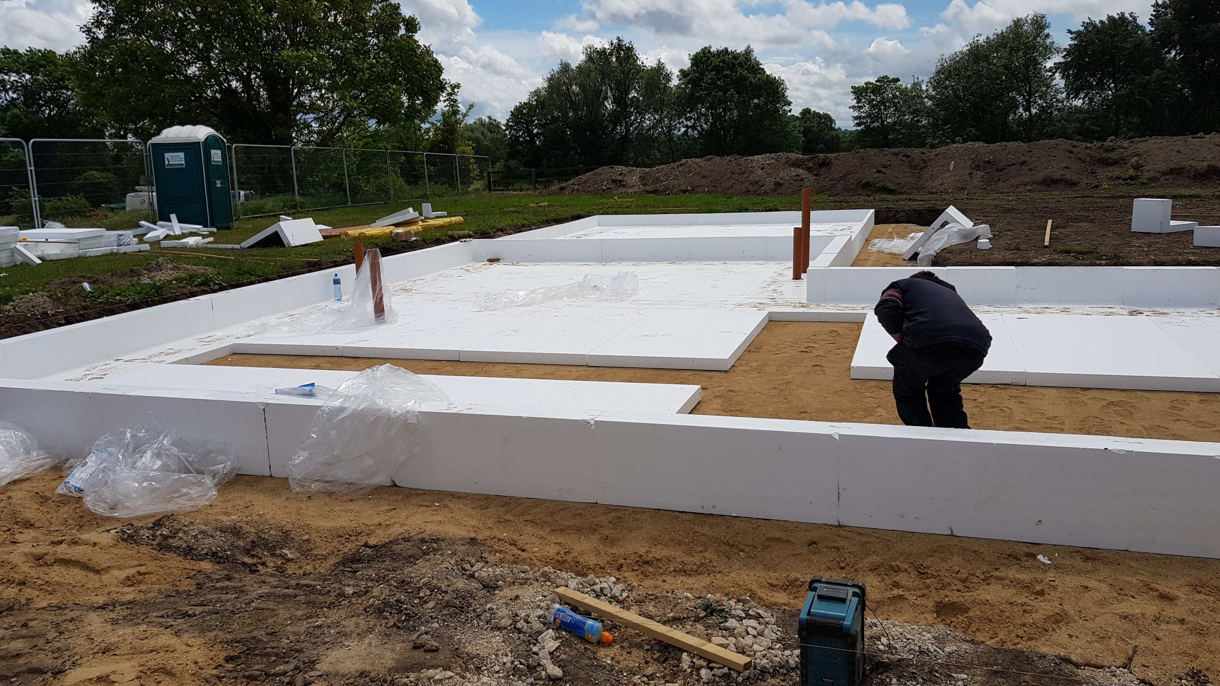
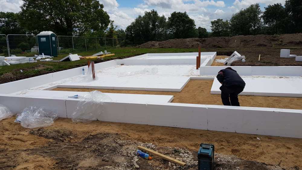
The thermostat senses the room temperature, operates the UFH zone valve to open/close the flow in that room. There are no sensors in the floor as it was impossible to cast them in the slab which was power floated to final finish on the day it was poured (yes, a long day, some 13hrs!) See photos.

-
Heatmiser Neostat v2 temperature sensor problem
Ultima357 replied to Ultima357's topic in Underfloor Heating
We are not thin screed. The entire house sits on and in 150 - 300mm of polystyrene, so the UFH pipes were cast into the slab, effectively a 155 ton thermal mass. This greatly improves the temperature stability. Floors are largely carpeted with suitable low tog underlay and carpet because that's what we prefer. If we run all loops at once, this is not effective or efficient as with 1.5km of pipes, it's quite a substantial system, (253m2 single storey BTW). So individual room control is very desirable and was part of the design, especially as we keep some cooler than others. By controlling when/where we heat, I can use the 6 hrs of 7p/kwhr overnight rate to maximum benefit, topping up during the day from battery and then grid when battery is exhausted. Overall, our average cost is sub 12p/kwhr and the cost of heating & hot water has averaged £227 per year over the last 3 years which is I'm sure you can agree, pretty much perfect. We run at 23deg in our active rooms and 22 in others, plus the 140m2 of warm attic as insulated at roof level in the main part of the house (400mm Warmcel). On really cold days, the rooms will heat cycle around once an hour maximum, mostly closer to once every couple of hours which is acceptable I think. -
Heatmiser Neostat v2 temperature sensor problem
Ultima357 replied to Ultima357's topic in Underfloor Heating
Well you can calibrate the Neostat to match if you want to. I used a reference thermometer. And yes, there's no real alternative to the Heatmiser system, so we are stuck to make the best of it. -
Heatmiser Neostat v2 temperature sensor problem
Ultima357 replied to Ultima357's topic in Underfloor Heating
The UFH is divided into 14 zones and something has to tell it to switch on is the reason for room stats. With MVHR too, and being super sealed (0.17ach) and the thermal performance, individual rooms can change considerably with solar gain, so we need that level of granularity in control. Doesn't seem to be any other system that challenges the Heatmiser/Neostat either unfortunately. -
Heatmiser Neostat v2 temperature sensor problem
Ultima357 replied to Ultima357's topic in Underfloor Heating
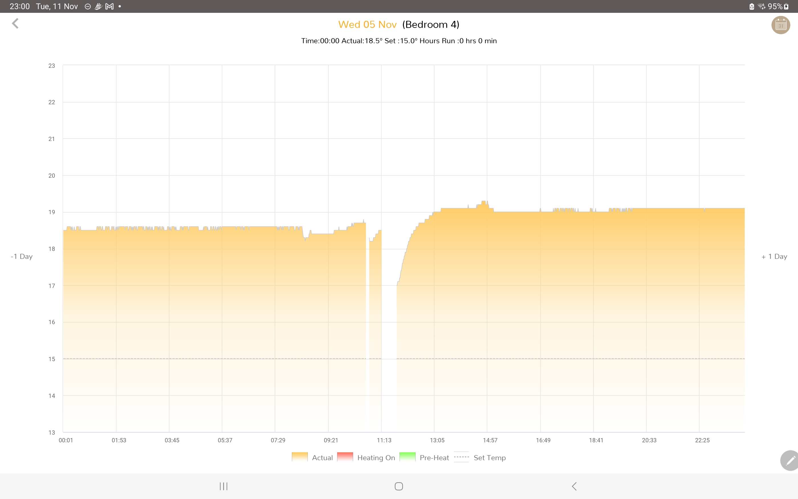
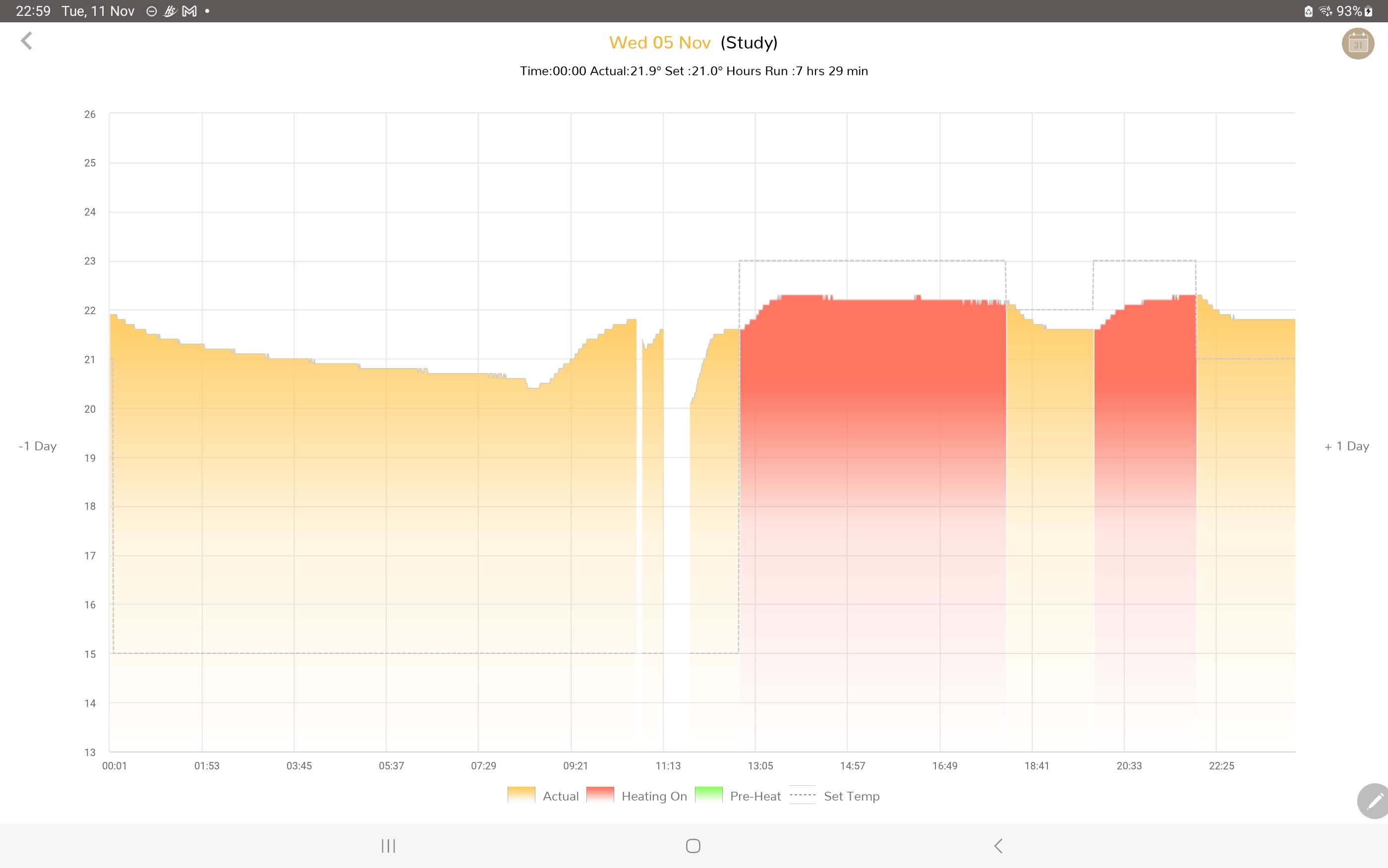
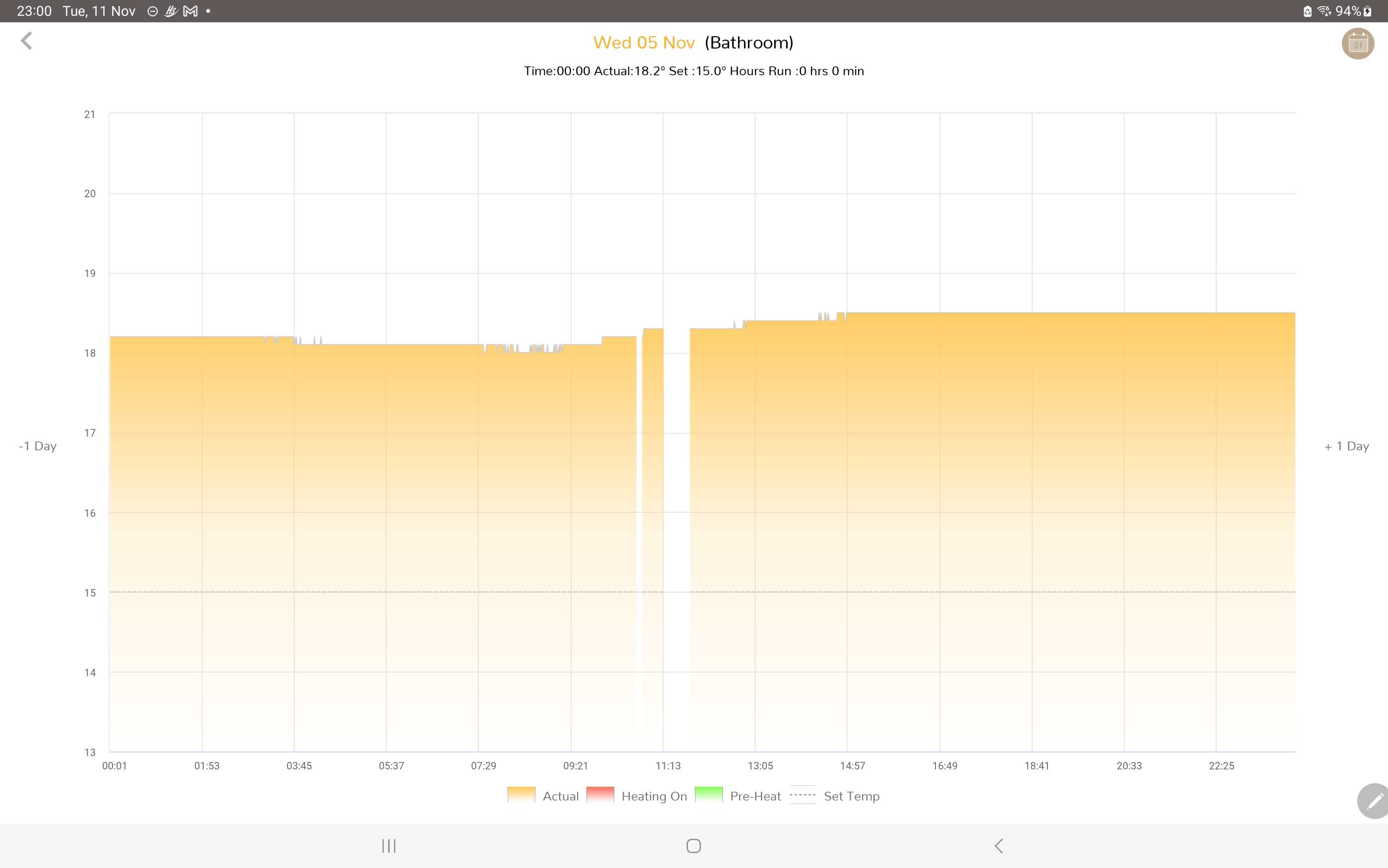
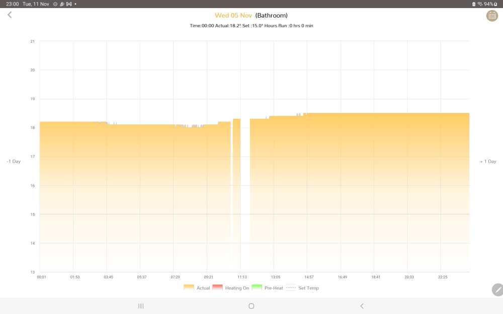
At the start of this thread, I posted the unsatisfactory temperate sensing of these units due to the heat from the transformer and came up with the modified spacer to improve it. Heatmiser never accepted that they had a problem. I don't know why, but I didn't think of a proof of this bad sensing until a heating system fault occurred last week when the Heatmiser system was turned off for a while during the fault correction (an unassociated ASHP issue). The penny dropped when I looked back at the extended profiles of the various stats and found that despite a fairly stable temperature (house is large, passive and super airtight), once switched off the recorded temperature at restart was significantly lower than the powered temperature recorded prior to being turned off. Additionally, when turned back on, even though no heating was being input, the temperature climbed back up. NB, the study climb prior to being turned off was solar gain. To prove the point, the bathroom one is a remote head unit and unsurprisingly, temperature recorded across the power break was stable. QED Mr Heatmiser!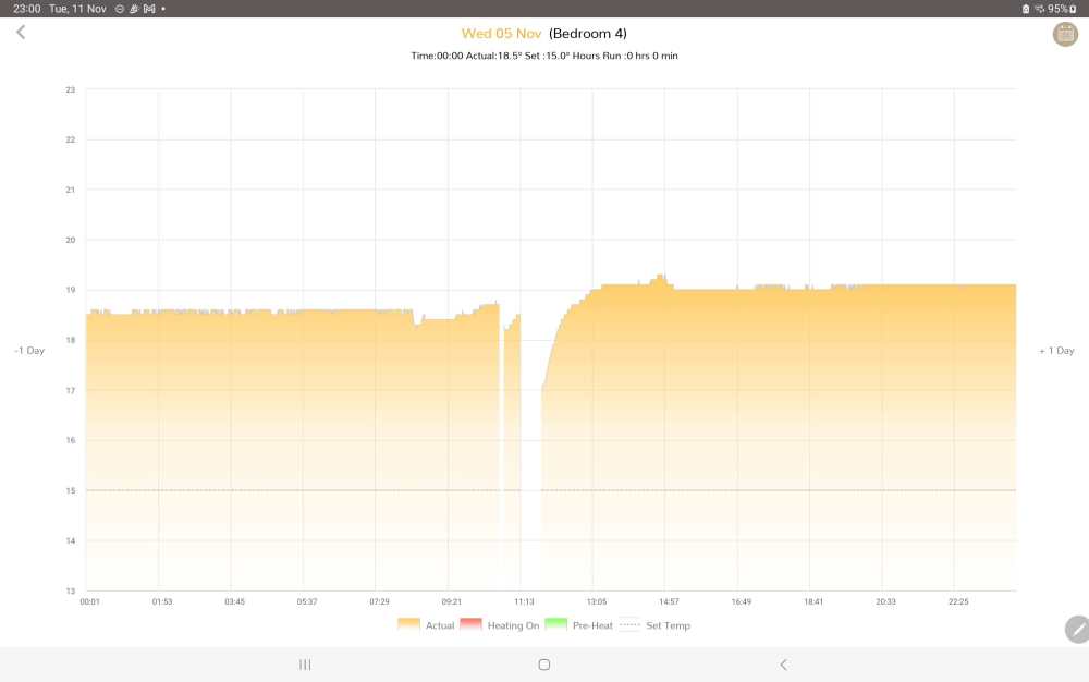

-
Sunny Boy SB3.0-1AV-40 continually rebooting
Ultima357 replied to Ultima357's topic in Photovoltaics (PV)
That's why I decided to replace them. You could easily spend a few hundred quid chasing your tail with tests etc, so simple to change out as 450w panels ard only about 84€. -
Sunny Boy SB3.0-1AV-40 continually rebooting
Ultima357 replied to Ultima357's topic in Photovoltaics (PV)
A bit of further info for the discussion. The PV system is mounted on steel frames on top of the flat roof which also has the steel framed solar hot water system, duly earthed as it also contains an immersion system. So the steel frames are also earthed and panels directly screwed to them. The panels are 14 years old, probably had 3 to 4 times the sun that UK panels have over this period. Rated at 30v, the 'good' ones showed around 26v on the day they were measured but the 'bad' ones were indicating 37v. So all a bit odd. Ground earth is flaky out there due to the rocky subsoil and immensely dry conditions. Eg, hasn't rained since April in any amount that did more than lay the dust for 30 minutes. The power grid is also flakey, giving frequent power cuts and brown outs, overvoltage spikes etc. I protect sensitive kit with regulators. As for risks earthing stuff on the roof re lightning, well the normal steel reinforced concrete frame means that the whole building will be effectively at earth potential and although thunderstorms are quite frequent, it is very rare to hear of any damage or fires being caused by strikes. -
Sunny Boy SB3.0-1AV-40 continually rebooting
Ultima357 replied to Ultima357's topic in Photovoltaics (PV)
14 years -
Sunny Boy SB3.0-1AV-40 continually rebooting
Ultima357 replied to Ultima357's topic in Photovoltaics (PV)
End solution. Well I managed to borrow a 2nd hand SMA inverter and plumb it in which proved that the issue was in the arrays. They appear to be leaking to earth. After metering each individual panel, 7 were clearly end of life and even getting an array of 10 that seemed OK, you could measure neutral to earth and see the voltage climb to more than 20v just before the inverter tripped out. So plan now is to renew the array and put in another earth rod. A job for the spring time. -
Sunny Boy SB3.0-1AV-40 continually rebooting
Ultima357 replied to Ultima357's topic in Photovoltaics (PV)
Not sure what the warranty is, but support is limited out here. Yes I meant MWh produced since installed. Just checked, warranty 5 Yr. 10 Yr if installed after October 2021. Dang! -
Sunny Boy SB3.0-1AV-40 continually rebooting
Ultima357 replied to Ultima357's topic in Photovoltaics (PV)
Yep, meant MWh. -
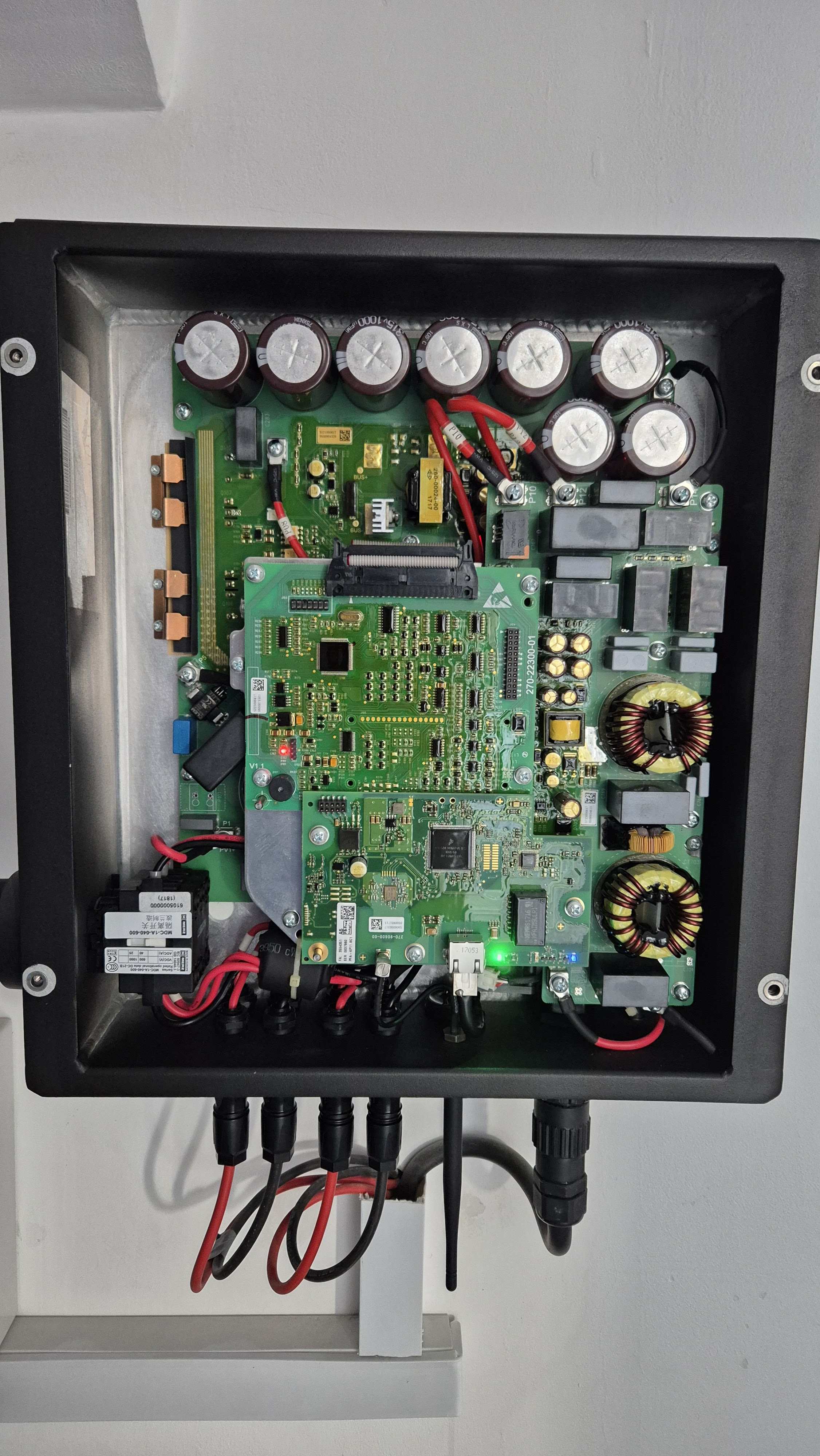
Hi everyone. I have a Sunny Boy SB3.0-1AV-40 inverter, about 7 years old now, having churned out just over 35Mw in its life. It has 2 strings of 10 x 150w panels each, all due south and no shading. (Location in sunny Cyprus, hence the power generation). I'm now trying to fault find an issue where it is constantly restarting, relay clicking in and out, sometimes a few times a minute. It's not consistent which is also a head scratcher but always occurs from around 9am to 11:30 ish but can also happen at other times too. So far I've found the strings are iffy, panels now some 12yr+ old as previously powered a battery support system. One string is 265v and the other 365v. Plan to sort that out this weekend having sourced some equivalent replacements from a similar system that has been dismantled. £0 so a good find. But, not withstanding the above, further experimentation of running on just one string, it still exhibits the same problem. I've only got basic voltmeter and current clamp and the inside of the inverter is one of layered circuit boards, so very unfriendly. Nothing obvious fried or smelly though. Curiously, the 8 large capacitors at the top of the unit are 4 at 178v and 4 at 0v. That seems odd. Measured simply from capacitor top to ground. Unable to find a circuit diagram, so at a loss as to what else to measure, but beginning to think the inverter is the issue. Oh, no great problems reported on the monitor either. Used to get grid over voltage shutdown but not now, it being typically 240 to 245v. Any ideas?
-
Yes it is a pole transformer serving around 18 properties. I've since emailed UKPN but they have not responded. May do some more tests now I have a bit of time in hand and just meter out the incomer into the house to check there's no issue on my side, but the voltage doesn't uniformly track the load, so I'm fairly sure that it is external bolt drop.
-
Brink bypass valve error
Ultima357 replied to Ultima357's topic in Mechanical Ventilation with Heat Recovery (MVHR)
Following a call to CVC, the company that originally supplied the unit, and after discussing the problem, the tech support team suggested a firmware flash and emailed me the files. Simple to apply via plug in USB slot. Update was automatically applied and the problem cured. Great support from the team at CVC Systems. -
MVHR Active Carbon Filter
Ultima357 replied to Ultima357's topic in Mechanical Ventilation with Heat Recovery (MVHR)
Yes there are ways to do it with varying airflow but with MVHR you don't have that control. The air filtration on agricultural machinery are also equipped with vortex filters. -
Hi everyone. My 4 Yr old Brink Flair 400 has just thrown up a wobbly on the bypass valve, putting up an error code and basically then not responding to my commands. The unit is doing the initialisation every so often, but then says error. Taking the exchanger out and inspecting the valve I can see no issues and it fully cycles during the initialisation. I've removed it and replaced it and can't see any damage or problems with the cabling, so a little bemused as to why I'm getting the error. I've powered down and rebooted, leaving it for a few hours in between, but still no joy. The only odd thing I can see is that during initialisation, it starts to move and then stops after the top edge has travelled around 6cm, shunts back a couple of cm then fully travels to the closed position, then returns to open. Only thing I can think is there must be a positional sensor that is not working properly. Any ideas?
-
MVHR Active Carbon Filter
Ultima357 replied to Ultima357's topic in Mechanical Ventilation with Heat Recovery (MVHR)
They look pretty good though you'd need some adaption to match the diameter of the inlet and outlet. And of course the space needed for the length of the inline configuration. You'd possibly also need to insulate the outside depending on the location of it. Can't see any reference to backpressure, but being made by Phresh and having such a large flow rate that shouldn't be an issue. Price wise probably cheaper than mine plus box materials. -
MVHR Active Carbon Filter
Ultima357 replied to Ultima357's topic in Mechanical Ventilation with Heat Recovery (MVHR)
To be honest, I've never looked inside the box since I screwed the lid down. I wouldn't think it would be a problem as the filter is very large, designed for 600m3 flow rate, so pulling a steady 100m3 or even flat out 330m3 in my case, I don't think that carbon dust will be an issue. Everything is static, no vibration, etc. I'm thinking that another fine enough filter to catch those very fine particles would put too much back pressure on it. -
MVHR Active Carbon Filter
Ultima357 replied to Ultima357's topic in Mechanical Ventilation with Heat Recovery (MVHR)
Sketch re above looking inside box.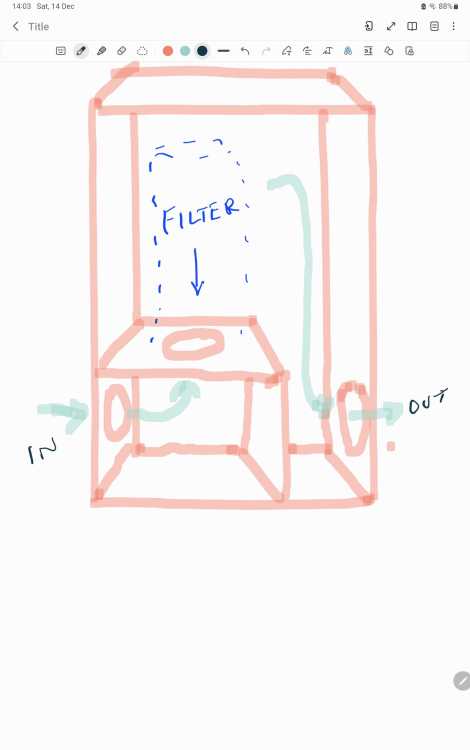
-
MVHR Active Carbon Filter
Ultima357 replied to Ultima357's topic in Mechanical Ventilation with Heat Recovery (MVHR)
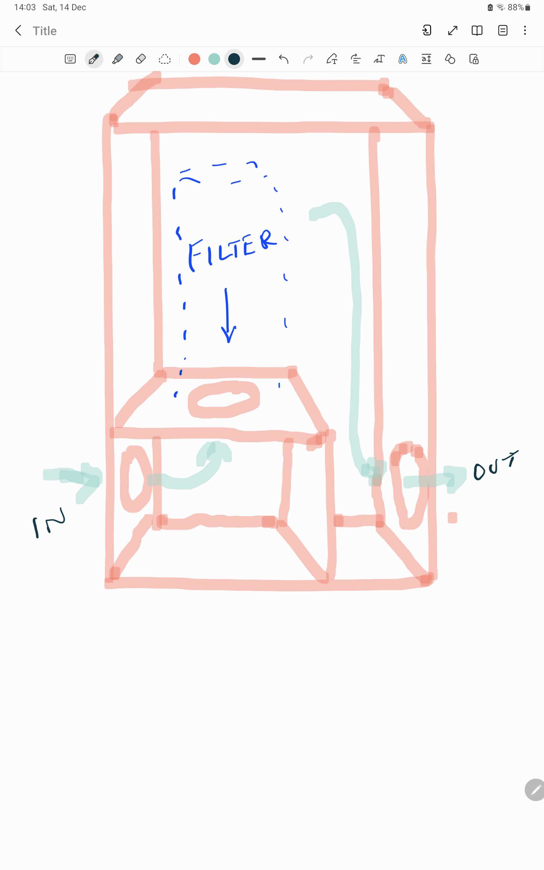
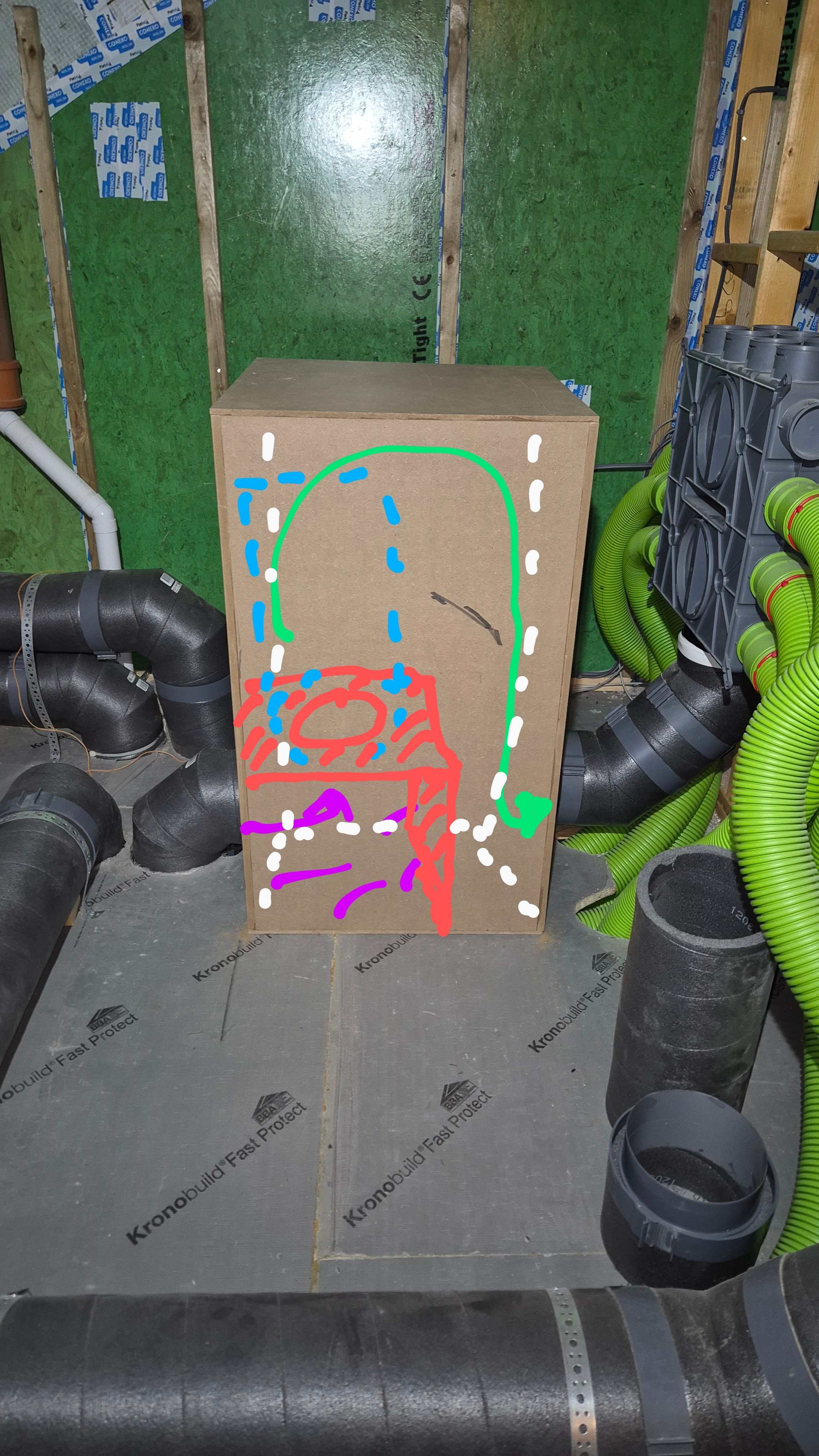
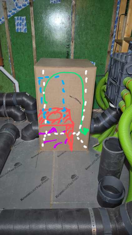
The baffle supports the filter which is mounted vertically, inlet at bottom and gives the airflow route. See picture. The red line is the baffle inside the box, the blue/red the filter and green represents the airflow. Basically the baffle divides the box internally to give separation of air so it has to flow through the filter. It's an L shape. The box is 600mm sq by 1000mm high. Second one shows the baffle inside in red, the dirty incoming in purple and green filtered air. Blue dashes the filter. The white dots the inside edges of the box.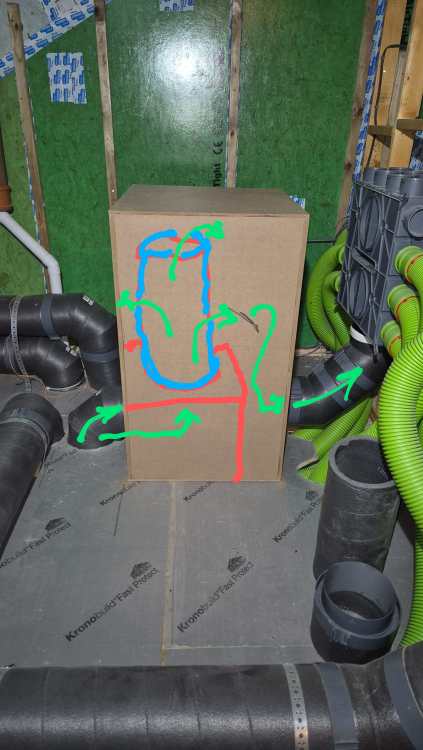
-
MVHR Active Carbon Filter
Ultima357 replied to Ultima357's topic in Mechanical Ventilation with Heat Recovery (MVHR)
Hi. My system pumps from the unit into the bottom of the box containing the filter. The filter sits above this on a baffle board, so the air pumps into the centre inlet of the filter and out the exterior of it. Then flows around the box back out to the manifold of the mvhr for house distribution. My neighbours love bonfires and this copes fine with them. Ditto the occasional smell of the countryside from muck spreading etc. So effectively I have a large box with a smaller box/baffle inside at the bottom which acts as a duct for the incoming air into the filter. If it doesn't make sense, let me know and I'll try and draw it up and post it on here. -
Heatmiser Neostat v2 temperature sensor problem
Ultima357 replied to Ultima357's topic in Underfloor Heating
Nope, never heard from them again. I got into 3D Printing since then and designed a vented spacer and posted on Thingverse which others have since used to overcome the problem. Nice to know that they have finally seen the error of their ways. -
Hi everyone. Just wondering if anybody has experienced low grid voltage in their supply? I run a self built passive house and have ASHP, solar battery (GivEnergy AIO), car charger etc and being on Octopus Intelligent Go, I have 6 hours of cheap rate overnight electric. My problem is that I can draw as much as 16.5kw whilst on the cheap rate and recently noticed that on these cold nights, the reported grid voltage has dropped to as low as 202vac. I noticed because the car charger dropped out and complained so have been keeping an eye on the situation. UK power networks unhelpfully told me they could only look when it is happening and to call them at that time which being usually between 2 and 3 am and not every night, is completely impractical. It has for instance only occurred twice in the last 8 days. As peak power pull only occurs when everything kicks in and ASHP is on top power, I can't easily time it, particularly as Octopus control when the car charger kicks in. My concern is that the low voltage will damage the ASHP and other motors such as fridge compressor as they will pull more current to compensate I believe. Does anyone have any knowledge of this and is it likely to do damage? Any good contacts (email preferably) at UKPN?