lineweight
-
Posts
91 -
Joined
-
Last visited
Everything posted by lineweight
-
Proper way to do a double 90deg gutter offset
lineweight replied to lineweight's topic in Rainwater, Guttering & SuDS
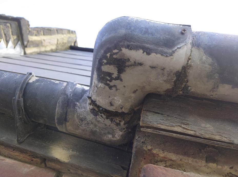
No, just ancient plastic. -
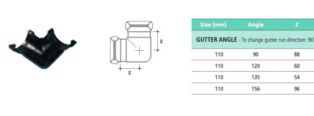
I need to replace this bodged bit of gutter. As you can see there is an offset in the gutter line - and the offset is about 130mm. My problem is that using two standard 90 degree corners, even if I butt them right up to one another, creates too much of an offset. As far as I can make out, it would end up with an offset of something like 260mm. Eg dimensions for Polypipe: Is there a "proper" way of doing this - am i obliged to go for a solvent weld system?
-
Feasible to retrofit an "over-fascia" vent?
lineweight replied to lineweight's topic in Roofing, Tiling & Slating
Ah, I see. In the photo it looks like the membrane is sitting on top of the vent strip (ie the vent leads to space under the membrane) but I think I se now it's actually not and it's just a trick of the camera angle. -
Feasible to retrofit an "over-fascia" vent?
lineweight replied to lineweight's topic in Roofing, Tiling & Slating
Hm, in that scenario I guess I would have thought the plastic strip would want to sit over the ventilator, rather than being under it, but maybe I am misunderstanding. -
Feasible to retrofit an "over-fascia" vent?
lineweight replied to lineweight's topic in Roofing, Tiling & Slating
Any particular reason you'd use that rather than the one in my OP? -
Feasible to retrofit an "over-fascia" vent?
lineweight replied to lineweight's topic in Roofing, Tiling & Slating
Yes there is. The only thing slightly nonstandard is that it's a mansard roof so the roof pitch is pretty steep where it meets the eaves. -
I'm going to replace a rotten timber eaves board & ropey guttering with new. Will probably replace with a PVC eaves board, and I'd like to improve the ventilation at the same time. The eaves board is tight against the brickwork - no soffit to speak of, so soffit vents aren't an option. Can anyone tell me if it works to retrofit an over-fascia vent, eg this sort of thing https://www.roofingmegastore.co.uk/manthorpe-25mm-over-fascia-vent-37-x-46-x-1000mm-black-pack-of-20.html - or is that not really possible without removing the bottom row of slates? I am thinking that I would attached it to the top of the eaves board before installing the eaves board - then push it up under the slates and fix.
-
Automist Fire Suppressor
lineweight replied to Ferdinand's topic in General Self Build & DIY Discussion
I am bumping this thread because I am wondering if some issue has come up with these systems. When I look at the info on the Plumis website they mention an LABC Assured Detail (EW171) but the link to this brings me to an LABC page that says *Certification suspended pending review* https://www.labc.co.uk/business/labc-assured/ew171-plumis-automist-automatic-fire-suppression-device So does this mean that using these systems eg. to allow open plan entrance storeys in 3-storey dwellings has been called into question? Is this something Grenfell related? -
Architect Invoice Much Higher than Expected - Options?
lineweight replied to greido's topic in Surveyors & Architects
Nor are they likely to give you a proper set of scale drawings so that you can know exactly what you are supposed to be getting, before they start work. -
Architect Invoice Much Higher than Expected - Options?
lineweight replied to greido's topic in Surveyors & Architects
Then they are not registered architects. Technically they should not be describing themselves to you as "Architects". It sounds like you agreed that they should do some more work (a few hours) to find a less expensive solution for you, and they did that, and succeeded in proposing something less expensive? So the dispute you have is whether 15 hours is "a few hours". I think that 15 hours is more than "a few hours" so it is fair for you to challenge them on that. If they failed to explain to you that the revised designs would then require further detailed input from them and the structural engineer - then I think they should have been clear to you about that, if you are a domestic rather than professional client. But I'd state to them how it looks from your perspective, why you are not entirely happy and see how they respond. Their response might inform whether you want to continue with them. The relationship between designer and client on a domestic project requires some level of trust in both directions. Don't assume that you'll necessarily have a better experience with a building company, as has been suggested. You might or might not. There are plenty of building companies who fail to respond to communication, or present extra costs without warning, or who don't stick to agreements. Of course there are also excellent builders out there. -
Getting a WC and bath waste into the same branch pipe
lineweight replied to lineweight's topic in Waste & Sewerage
As I've shown it, the top of the 110mm pipe would be just about at floor level where the connection was made. That obviously wouldn't work in all cases - but in this case it could, because of the way the floor joists work. Then there is still enough height difference between there and the outlet level for a bath. I've drawn it as if the connection goes vertically into the top of the pipe. But would it even have to? Approved Document H doesn't seem to have a lot to say about what should happen when one branch pipe joins into another. What it does say is: That seems to allow for the possibility that the smaller pipe could simply join into the side of the 110mm one. The soil manifold, I think, is mainly designed to deal with the Doc H requirements for what happens when a branch pipe connects into a stack. But that's not actually what I'm looking to do here.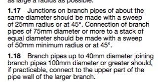
-
Getting a WC and bath waste into the same branch pipe
lineweight replied to lineweight's topic in Waste & Sewerage
Out of interest what would be your reason for preferring it? Because I thought I preferred it but then once I'd drawn it out, I couldn't actually come up with a reason why it's any better than the second one. -
Getting a WC and bath waste into the same branch pipe
lineweight replied to lineweight's topic in Waste & Sewerage
It's all hovering around the 3m / 4m limits. The plan arrangement is slightly in flux because the levels thing, and detail of the pipe exit through the wall is what is critical and what I want to try and pin down first. -
Getting a WC and bath waste into the same branch pipe
lineweight replied to lineweight's topic in Waste & Sewerage
An AAV could be provided if necessary. Yes, in theory the bath/basin pipe could go out through the wall independently, and in principle that would be better, but in reality it would get very complicated and messy to try and take two pipes through where they'd have to go. So this is what I'm really trying to avoid. It would probably be less messy to drop them into the soil manifold, then down into the room below and then out through the wall there. But ideally, would want to avoid having to do that too. -
Getting a WC and bath waste into the same branch pipe
lineweight replied to lineweight's topic in Waste & Sewerage
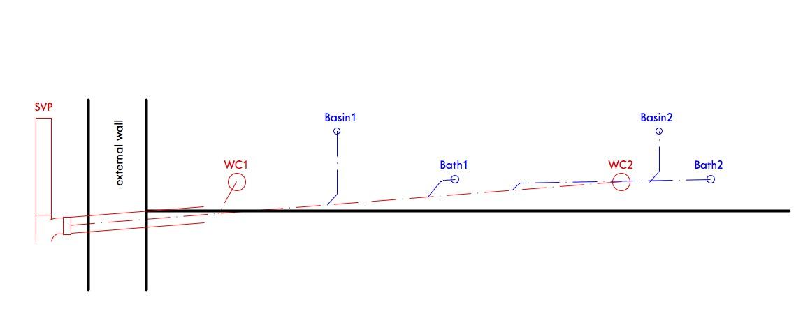
...and if my second option is basically ok, does that mean that something like this would be ok: If the main 100mm pipe were running *below* the floor (so 300mm or so lower down) then it would be different.... but when I look at this, it doesn't look right because the baths and the WCs all look too closely connected and asking for problems if there's a blockage. Is there somewhere in the building regs or BS that specifically outlaws what I've drawn here?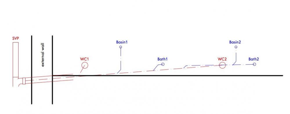
-
Getting a WC and bath waste into the same branch pipe
lineweight replied to lineweight's topic in Waste & Sewerage
What height above the 4" is your bath outlet? I guess what is in the back of my mind is the branch pipe blocking somewhere before it meets the vertical stack ... and then it backing up and unpleasant things appearing in the bath. This scenario is avoided when the WC and the bath are on different branches, independently connected into the stack. -
Getting a WC and bath waste into the same branch pipe
lineweight replied to lineweight's topic in Waste & Sewerage
Sure. It's 2nd floor at loft level. Loft extension. Messy/difficult to drop into room below. There's really only one external wall that it can exit through because of drain positions and other stuff. The reason I'd like to just have one pipe pass through the wall is that the wall is actually part roof/part wall and what's going on just there is already pretty complicated in terms of flashings, structure and so on. -
Getting a WC and bath waste into the same branch pipe
lineweight replied to lineweight's topic in Waste & Sewerage
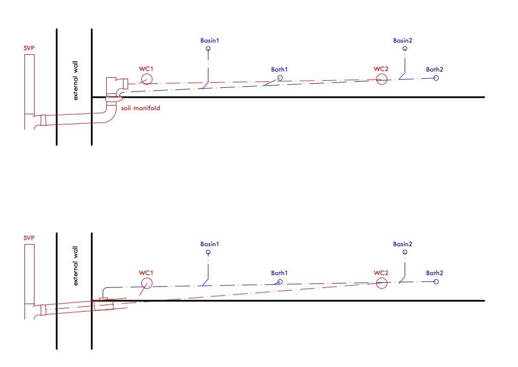
Essentially these are the two options I'm looking at. Top one, waste pipe is laid from WC2 to a "soil manifold" type connector at the most gradual gradient allowed and connects in as shown. Then, waste pipe from Bath2 can run at a slightly steeper gradient and connect in as shown. Bottom one, waste pipe from bath2 is laid as shallow as is allowed, then drops into a simple boss connection on the larger pipe, which is near horizontal at that point. Then, the larger waste pipe starting from WC2 runs at the steeper gradient, to whatever that level has to be. The bottom option seems the more straightforward. But is it ok just to drop the 'blue' pipe into the 'red' one like that, and if so does it have to go in the top or can it just go in the side (in which case the main pipe might barely have to drop below floor level).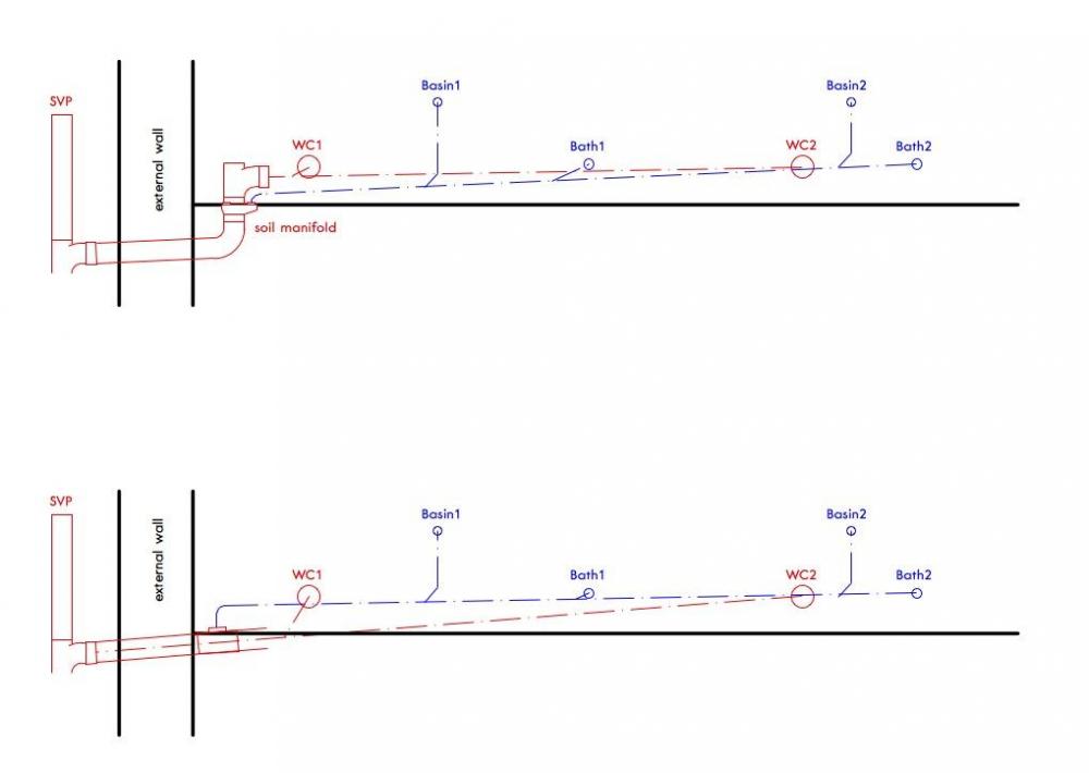
-
Getting a WC and bath waste into the same branch pipe
lineweight replied to lineweight's topic in Waste & Sewerage
Thank you but I already have! The question is more about what's allowed or considered best practice. I've not found any products that are specifically aimed at the situation I describe - the "Soil Manifold" sometimes also known as a "Collar Boss", as I already mentioned, is the one that comes closest. Even a close reading of Approved Document H, as well as BS 12056, doesn't throw much light on what is or isn't supposed to happen, if I want to connect a WC and a bath into the same branch pipe. I can't see anything that explicitly forbids it, but nor can I see anything that mentions it as a scenario that might arise. -
Is there a proper, or best, way of doing this? This situation arises where you want to have only one pipe emerging through an external wall, but you want to connect multiple appliances into the soil stack. And where you can't run the horizontal branch under the floor, and drop each appliance vertically into it. Is the solution to run them to a soil manifold, then there is a bend immediately underneath the manifold which takes the pipe horizontally through the wall? Or are there any other options?
-
From an architect's point of view that initial 'feasibility' or 'outline design' stage can be the most difficult to price because the amount of work involved can be very variable. It might be that you pretty much know what you want, and it's just a matter of drawing up some basic plans to check it all works in principle, and it does, and the job is pretty much done. On the other hand, you might think you know what you want, but would also like to have some other options suggested to you. Or, what you think you want turns out not to work. And you might be very decisive or you might be quite indecisive and the process ends up going through quite a lot of options and sub-options, or you change your mind about something once one design has already been pursued in a fair bit of detail. Then there might be unexpected complications that make the project more difficult than it appears at the outset, or various unknowns that arise. Some of these kinds of things mean that it turns out you can't actually complete the 'feasibility' stage without doing some things that might normally come at a later stage. For example, perhaps you need to get a structural engineer involved to know whether something's going to work. Or, you might decide it makes sense to make a planning application or initial enquiry, before going down too far down the line with something that turns out to be a no-no from a planning point of view. And then there's quite a variation in what can be presented as far as drawings are concerned. Some basic floorplan layouts, or detailed 3d visualisations? There's a judgement about what's necessary to help someone make a well informed decision, and what's overkill. I guess my advice would be to pay most attention to the quotes which are accompanied with a bit of detail about what they actually propose to do for that "feasibility" stage. Where they simply state "feasibility" and then a price, then you don't really know what they are assuming or what you're getting. And it will give you a clue about whether their expectations broadly match with yours. Have they given an estimate, say, of how many face-to-face meetings they expect to have with you? If an architect has come to see you, and look at the property, or at least had a bit of a chat with you on the phone, then that's probably a good sign that they've put some thought into what's actually likely to be involved - including getting an idea of what sort of client you might be, and what you actually want.
-
I think at least 150mm would be needed at an eaves, where you'd probably have a near-flat gutter and where you are collecting water from a large area of roof. Typical details suggest that less is considered necessary at abutments where it's running parallel to the slope of the roof. That I imagine is because the water will run away quickly on the steep slope, and it's not gathered from a large area of roof so won't be large in quantity. The only way for the water to build up depth would be if there was some kind of blockage (which is what would worry me with hidden gutters). But my understanding is that the typical 150mm upstand is not just about preventing water from overtopping it - but to protect the lowest part of a wall from getting saturated from water splashing off a roof surface next to it. That would be an argument for taking any leadwork somewhat above the top of the tiles even if there's a dropped gutter. It becomes irrelevant if the lead runs all the way up a small upstand that is less than 150mm though. So the main question for me is whether tucking lead in under a tiling undercloak is a conventional detail that's recognised as an adequate way of securing the lead.
-
From an architect's point of view, the amount of work involved in a £50k project is not - say - 33% of the amount of work involved in a £150k project. It might actually be 60% or 80%. Also, there are 50k projects that need a lot of design input (you want to take time looking at a few different options, or what you want to achieve requires some careful and thoughtful planning) and there are 50k projects that don't need a lot of design input (you pretty much know what you want, and it's standard stuff). This is one reason why adopting a % approach to small projects really doesn't make sense. If you approach an architect for a small project like this, you need to explain as best as you can what you are actually after, and they then have to try and make a judgement of how much work that will involve for them. It might well be that all you need is a structural engineer or a technician. Just don't expect them to give you any design input beyond purely technical considerations.
-
You might expect something like this to span between a larger member (like you have on the left) and something else, like a wall, to provide some mid-point support to those rafters. But it only spans to a regular rafter on the right. Does the layout of the house suggest that there might originally have been a wall in that location - under the 3rd rafter? If so, maybe there is something that was once there, which was removed without the support it provided being replaced. Is there an "intentional" change in pitch of the roof when you look at it from outside? Is the diagonal thing you can see on the right, the underside of a valley between two roof pitches at right angles to each other?
-
Thinking about this further - if you do it as a single lap, what is the logic that says there needs to be 150mm from gutter bottom to the underside of the tiles on the *higher* roof but not on the *lower* roof? The "single steps with secret gutter" detail from the Calder leaflet shows much less than 150mm from the gutter bottom to the underside of the tiles visible there. That's in common with other "secret gutter" details where the roofs are at the same level on each side - it appears it's considered acceptable for the bottom of that gutter only to be about the depth of a tiling batten below the underside of the tiles on each side. So it seems to me that the 150mm requirement then becomes redundant.