CH_18
-
Posts
46 -
Joined
-
Last visited
Everything posted by CH_18
-
OK bit more progress on this. I'm even more dumbfounded. So I had a hose constantly on different parts of the roof flat out at hour intervals this week and nothing shown up on the inside. No patches, no streaks, nothing. I took a panel off (in the rain) to expose the GSE tray underneath and there was no running water on the tray, the top flashing and panel was taking the majority of the water away, but what I did notice was the tray had what looked like condensation on it, wiped it with my hand and was soaking. So is that what is showing up on the membrane?? Another test I did was put a piece of DPM across the opening in the tray to see which side of the DPM was getting wet. Went down this morning after rain, wet patches visible on the inside again, pulled the DPM out and found that the external side was dry and the internal side was wet with condensation?? So seems like possibly condensation but I still don't understand the science on it 🤷🏼♂️
-
Yeah good call with the 600 x 600 squares, might be a bit easier. Not looking forward to it put it that way 🤦 Any more gems to make the junction at the wall plate a bit easier? Thanks
-
Yeah sorry I added that pic just as an example. It's a roof with attic trusses so need to work around the timber uprights of the dwarf wall etc
-
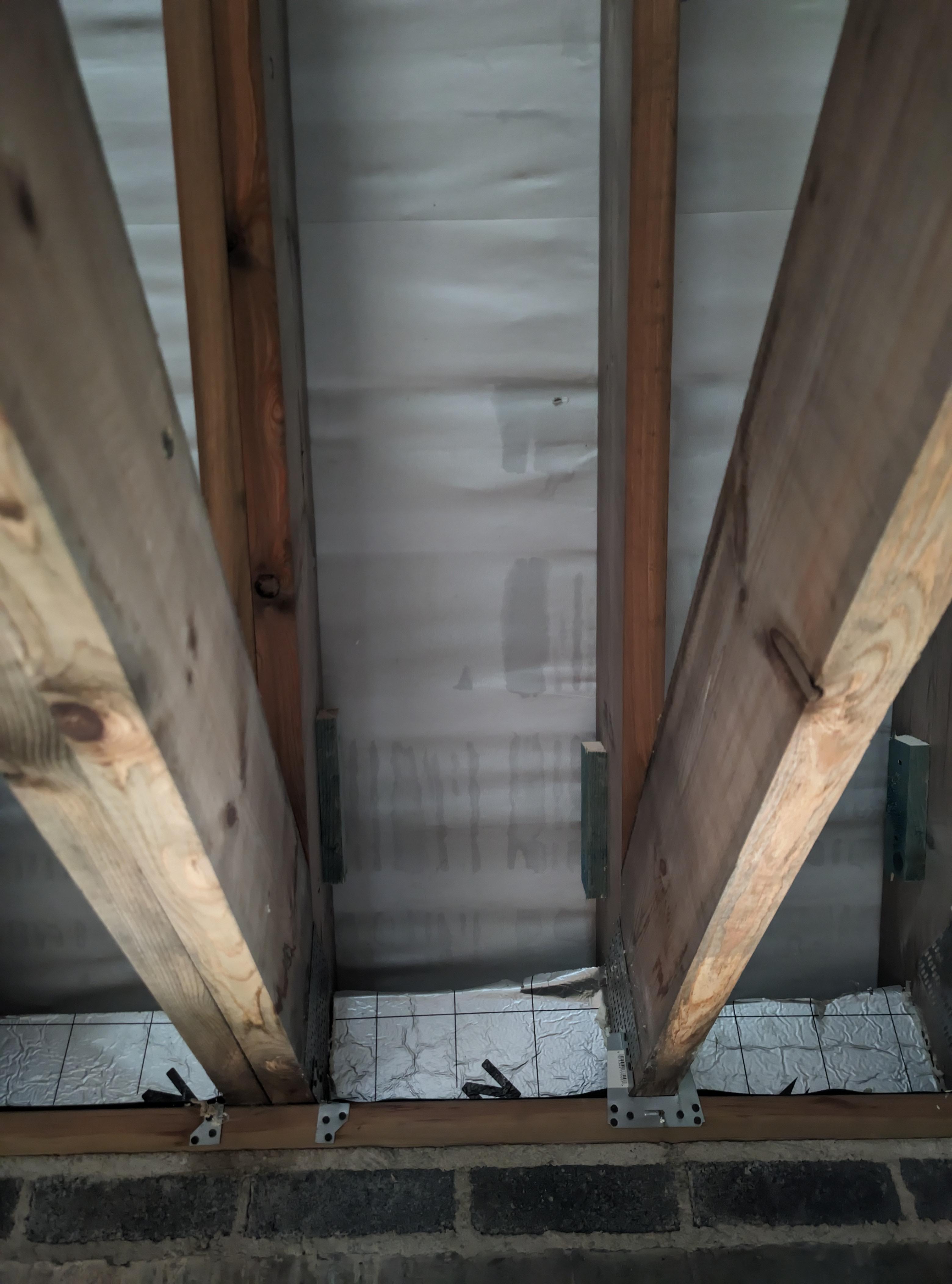
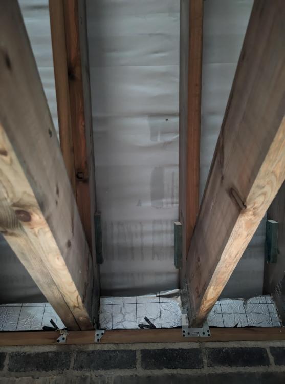
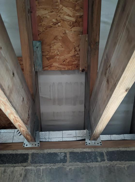
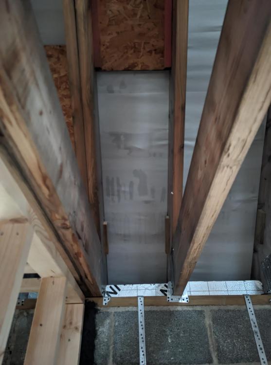
I have (maybe stupidly) decided to insulate my roof all the way down to the eaves to maintain a good thermal envelope with the wall insulation. All good. However, I now need to find a clever way to maintain the VCL/airtightness layer from the top all the way down to the walls whilst cutting around the dwarf wall timbers and floor chords of the trusses? Any ideas/tips how to maintain a good seal through and around the timbers and to make this as unfiddly as possible. Thanks
-
VCL across bottom chord of attic trusses
CH_18 replied to MortarThePoint's topic in Lofts, Dormers & Loft Conversions
Hi mate, sorry to resurrect this thread from the dead but did you come to a solution for this? I have the exact same issue of maintaining a continuous VCL through the dwarf wall timbers and truss chords. Thanks mate -
Currently doing a bathroom renovation and need to mount something between studs to fix showers/mirrors/shower screens etc. Tile backer boards will then go over the top. I know ply is the obvious answer but I have loads of 22mm P5 chipboard flooring offcuts floating around, would this be OK to use as a baseboard for mounting? Cheers
-
Hi everyone, We have recently had GSE in roof solar panels and trays fitted to our new build roof which is now complete and slated. Since then we have been getting wet patches/streaks on the membrane visible from below. My roofer has been round and said he's 90% sure it's condensation, which I'm not convinced by. The patches only form when it's raining which seems to be the big give away for me that it's water ingress and not condensation, but saying that, I'm no roofer. Any thoughts/advice would be much appreciated. Thanks
-
Thanks @JohnMo @Canski As I understand it (still learning), the 25mm upstand is there for thermal bridging and the foam strip is there for expansion of the slab? The longest length of slab is going to be 12m?
-
Hi everyone, I'm in the middle of putting my floor down for underfloor heating. Typical set up, Block and beam floor, Radon barrier, 150mm celotex, 75mm screed. I've put 25mm celotex around the perimeter upstands to eliminate thermal bridge, my question is, do I also need the foam expansion strip around the perimeter also? For reference it's a 75mm sand & cement screed with fibres. Thanks
-
Already built mate, currently 1st fixing 👍 Thanks for the reply, I'm finding hard to find info and understand what becomes a cold bridge, to my mind, the knee wall timbers could still be a cold bridge? Or with insulation in the rafters and under neath, is the cold bridge at the knee wall eliminated? Where does cold bridging stop? I've got stud walls screwed to some rafters, are they cold bridges? The caberfloor is screwed to the attic trusses, which is sat on the wall plate, are they cold bridges? Very complicated.
-
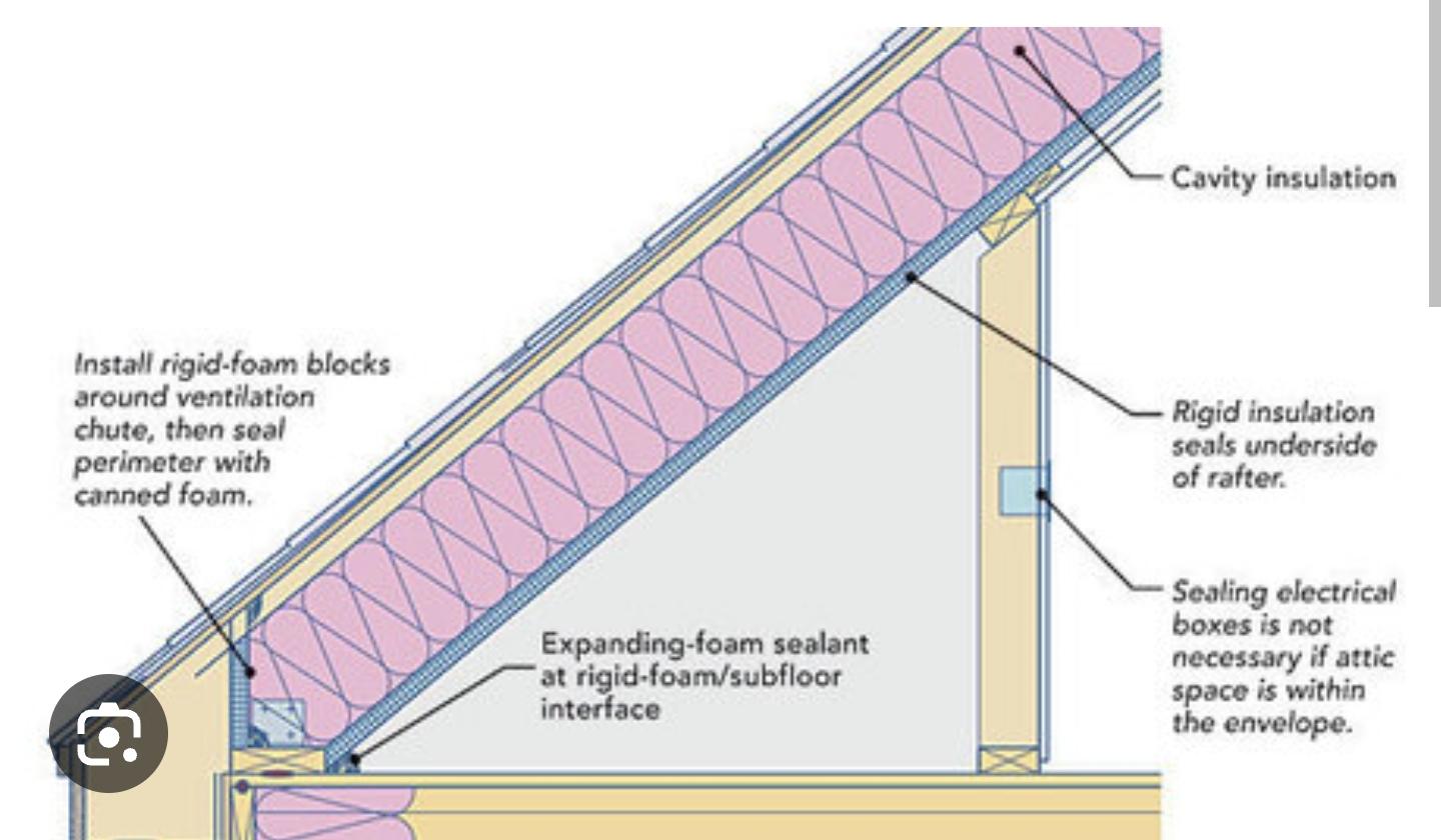
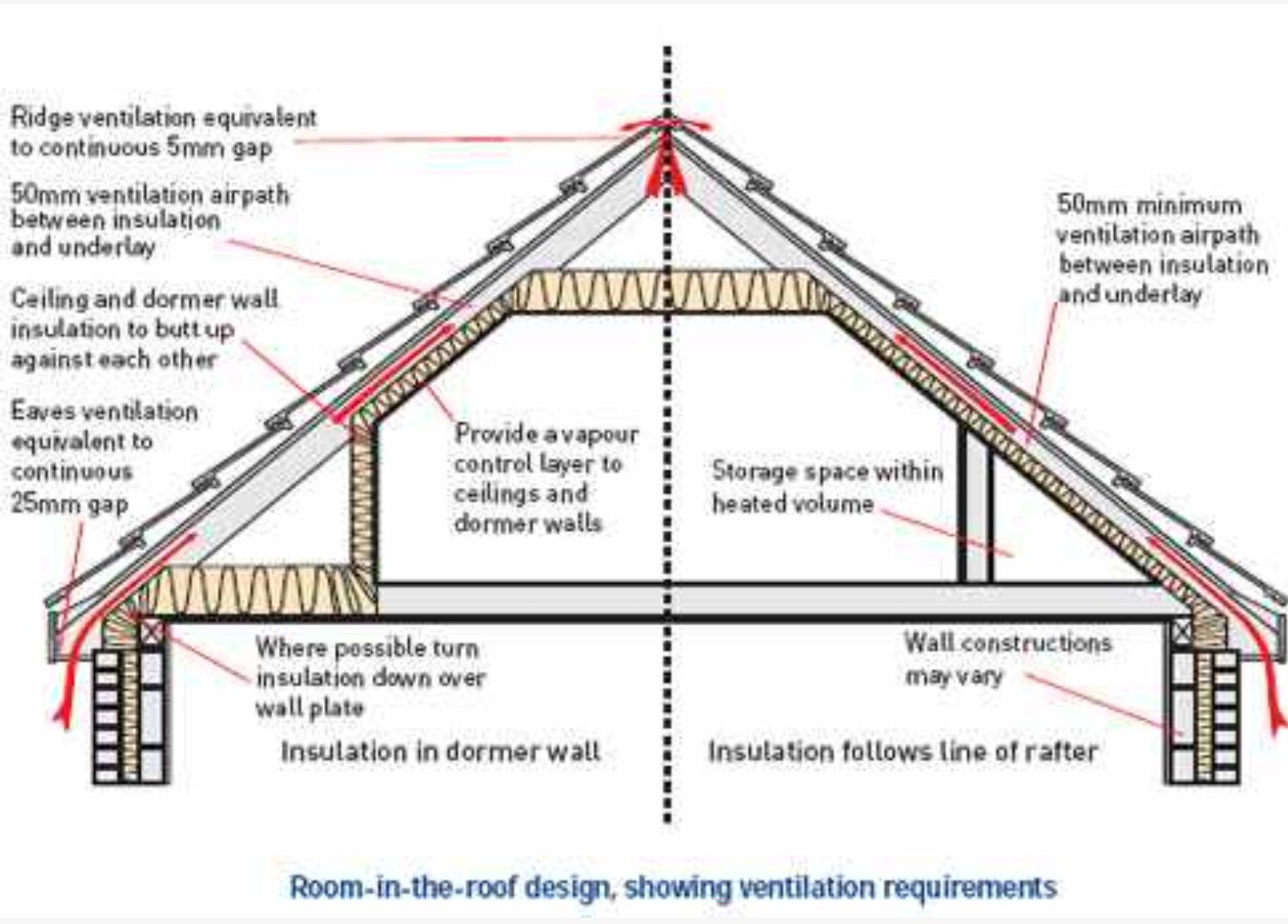
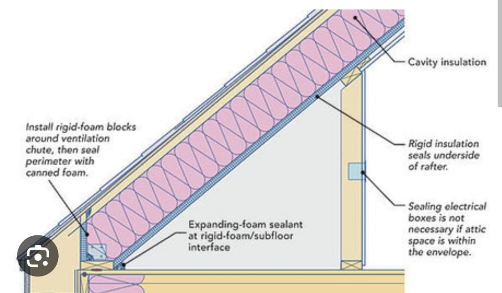
Hi all, The attached detail shows 2 options how to insulate the roof space of a room in roof. Our architect had specified the left hand option, 100mm between rafters of sloping roof and knee wall covered with a 50mm overlay then plasterboard. We would like to use the eaves space for storage/access so the right hand side option of insulating the roof line all the way down to the wall plate is my preferred way. Just seems way more energy efficient and easier for airtightness etc. So my plan was to put 100mm PIR in between rafters ideally from wall plate to ridge, overlay with 50mm celotex top to bottom and the install VCL and plasterboard. So my insulation and VCL envelope will follow the roof line. My questions are, if I insulate the roofline as preferred, Do I need to insulate the knee wall at all? Do I need to insulate the floor below the eaves space? Can I leave the eaves space with no plasterboard, and just plasterboard the room? thanks in advance

-
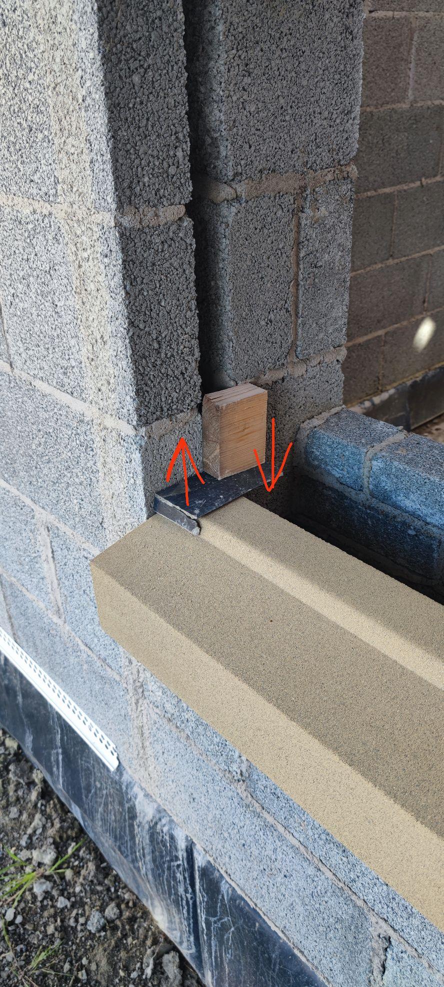
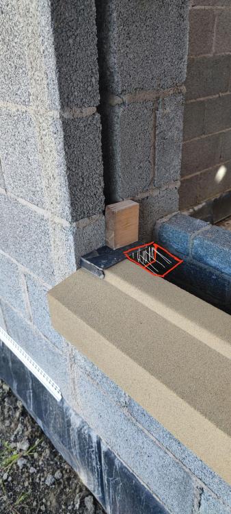
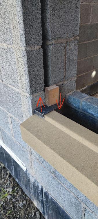
Been thinking about the best way to support the frame from the bottom, what about if I fix some angle brackets off the inside reveals. I've added a couple of pics to show. Will this be enough support? Obviously there will be straps also.

-
Thanks again @craig, appreciate your help. Option 2 (window positioned in the insulation layer) seems to be the way to go. My only issue is now figuring out a way to support the frame at the bottom. I will have the 150mm sill on the bottom but due to the weight and position of the frame (replicated by the piece of wood) the support would not be centered and may cause a cantilever effect (attached pic) Any ideas on how I can support the window? Metal dowels have been mentioned in other threads? Or simply angle iron/brackets? One last question, in normal situations where the frame is sitting on the sill, is this not a massive cold bridge? Or is there some sort of thermal break within the uPVC frame? Not really related but just curious. Everydays a school day 👍
-
Hi @craig Thanks for replying, top man 👍 Have you got any examples of the above details for me to see, struggling to picture the setup. Has the first detail you attached just got a normal uPVC stub sill? I was hoping to use a 150mm uPVC sill for option 2, do you think aluminium will be better? Suppose it is slimmer and more pleasing on the eye. One last question, if the window is fully in the insulation layer does the window need supporting from the bottom or can you fit windows with straps only? Thanks again for your reply 👍
-
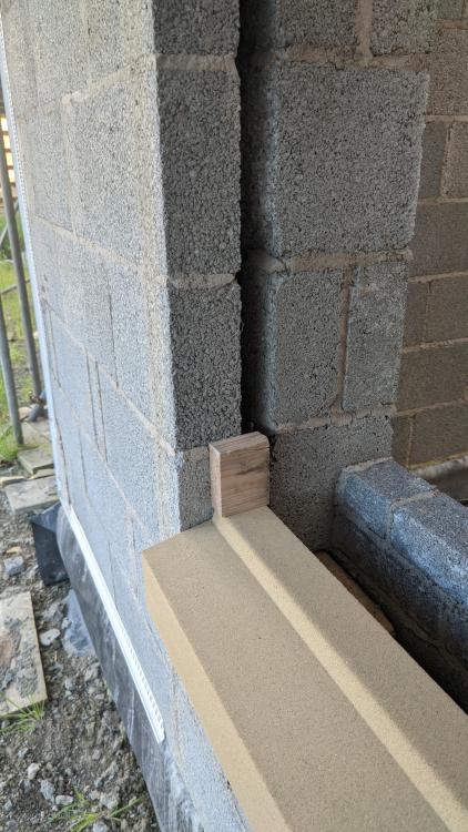
Option 2

-
Option 1
-
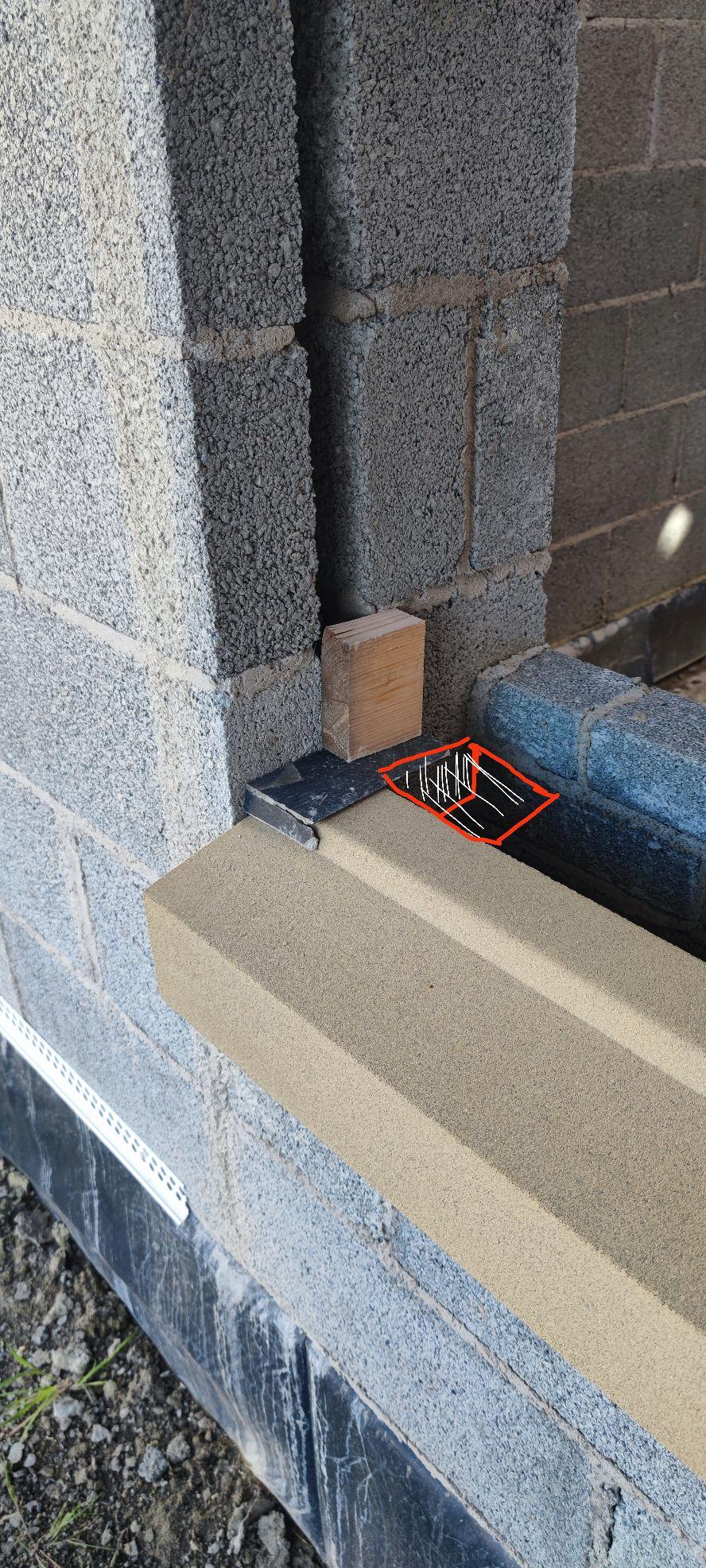
Hi there, Our sills are not quite deep enough so I have two options below (wood simulating window frame position). I have just placed the sill in position to test fit, DPC's will be going in. See next post for pics... Option 1 (left) Go with a smaller reveal, with a cold bridge and not much overhang on the sill, although still clear of drip groove, which I think looks neater. Or Option 2 (right) Set the window back in the insulation space and utilise a 150mm uPVC sill to cover the flat part of the stone sill. More overhang on the sill but possibly looks a bit naff? (They are just off cuts of slate to replicate colour of sill.) I would really like to have smaller reveals but not sure if the cold bridge is worth the risk? Does it make that much difference? Any input is appreciated. Thanks
-
As per the title, has anyone got any preference to which metal webbed joist manufacturer they prefer to use? From what I've been told, the mitek posi-joist system allows the designer to use staggered and single sided metal webbing on the design software? Looking at the design I've had it looks like some joists are staggered and not full length, which makes me think could be inferior in strength to the Wolf easi-joists maybe? Any ideas/input would be great, cheers
-
I would like clarification on this also.
-
Thanks for the replies everyone ? Yeah I think that's the way we'll be forced to go, strip foundation with b&b floor, followed by 150mm insulation plus screed. Could one option be to back fill with 600mm hardcore, put 50mm of sand in, then 300mm EPS blocks, then approx 200mm concrete? That would get us to around the magic number of 1.2m? Or would that build up not be structurally sound?
-
Hi everyone, first time poster ? We are due to start groundworks on our build in the next few weeks. We planned to go with a ground bearing slab but after digging some test holes found that theres approx 700mm of top soil that needs to come off he whole plot before starting. To level off the site, the developer had dug out from the high level side of the site and dumped it all on the low side to level it out. (Our plot is in the low side of the site.) From the test holes we worked out from the top of our foundations to our finished floor height will be 1.2m. With 600mm of hardcore in fill that leaves 600mm to be made up with concrete and insulation. Are there any other options to build up the 600mm? I keep reading about EPS blocks, could that be an option? Or is the only option (sounds probable) a beam and block suspended floor? Ideally we'd want to go down the slab route if possible. Having a cold breeze under the house doesn't sound very thermally efficient to me? Thanks in advance ?