


JackOrion
-
Posts
78 -
Joined
-
Last visited
JackOrion's Achievements

Member (3/5)
5
Reputation
-
Plant room layout / utilities / ducts etc
JackOrion replied to JackOrion's topic in New House & Self Build Design
There's no room around the outbuilding for the heat pump either unfortunately – we're building on the site of an old walled garden on a hillside, and have neighbouring properties on all sides. Outbuilding is about 45sqm total, although only 30sqm has UFH pipes in. (the remaining 15sqm has a cellar) -
Plant room layout / utilities / ducts etc
JackOrion replied to JackOrion's topic in New House & Self Build Design
I will ask the question, thanks. -
Plant room layout / utilities / ducts etc
JackOrion replied to JackOrion's topic in New House & Self Build Design
In terms of other services / ducting coming in, is it best for these to come through the slab in the same area of the room and distribute from there? Are they in one single opening in the slab or kept separate? -
Plant room layout / utilities / ducts etc
JackOrion replied to JackOrion's topic in New House & Self Build Design
Will double check cylinder size, many thanks for that. I missed the cable duct for car charger from the sketch.. that should have been on there as was spec'd by electrician. Good spot. The outbuilding is simple brick building (1900 ish) – but we insulated the floor with limecrete (https://mikewye.co.uk/product-category/limecrete-floor-systems/) and fitted UFH pipework in advance of house build, at the time thinking that would be our best option. -
Plant room layout / utilities / ducts etc
JackOrion replied to JackOrion's topic in New House & Self Build Design
Buffer was in architects' floor plan, heating engineer did also spec one but I will double check whether this is needed. The ASHP was on the other side of external wall on the original plan, but the path there is only 1.5m wide between house and retaining wall, so there isn't room unfortunately. -
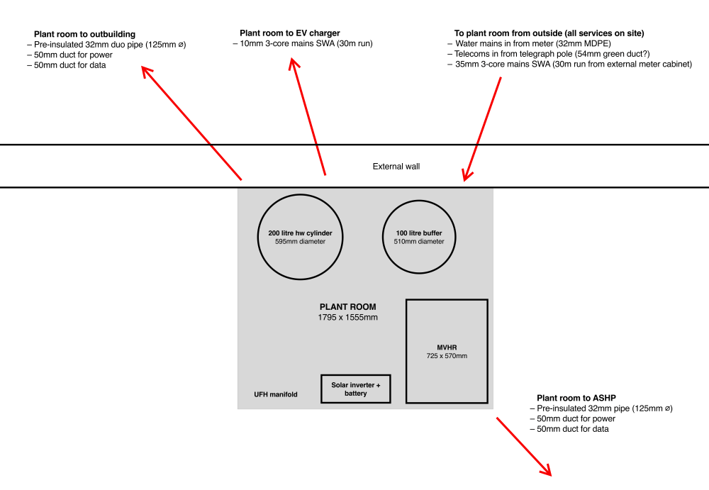
We are just going over plant room layout as trenches are being starting to be dug for services. Architects gave us initial layout for plant room which is in the centre of the house (2 bed bungalow, with small brick outbuilding which will be used for workspace). Simplified sketch is below with kit sizes to scale. Red arrows show ins and outs. Unsure how realistic this looks! Obviously keen to get it right before pipework is laid and any concrete poured. As ever any comments more than welcome. – We are building to passive principles so assuming all these should be coming up through the slab? – Should everything come in using ducts? (other than the 125mm pre-insulated pipe?) – Should these ducts be sealed / grommeted / something else? – How best to choose position of incoming / outgoing ducts? All new to us.. architects gave a general idea but not much else. Groundworks team are great but not experienced with passive side of things. Many thanks in advance 🙂
-
100mm perforated pipe... recommendations
JackOrion replied to JackOrion's topic in Landscaping, Decking & Patios
The aggregates supplier said similar re: 6N and fines. Will investigate further. -
100mm perforated pipe... recommendations
JackOrion replied to JackOrion's topic in Landscaping, Decking & Patios
The pea gravel spec came from the gabion engineer, in this case it's within backfill that is specified as 6N. Attachment here.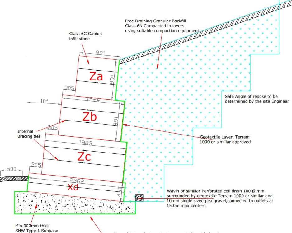
-
100mm perforated pipe... recommendations
JackOrion replied to JackOrion's topic in Landscaping, Decking & Patios
Thanks all. Yes, will be using pea gravel and T1000: Wavin or similar Perforated coil drain 100 Ø mm surrounded by geotextile Terram 1000 or similar and 10mm single sized pea gravel, connected to outlets at 15.0m max centres. Baskets will be on a 300mm SHW Type 1 sub-base. And below that sub-base we need to put in drilled piles that are tied into the foundations (also on piles) via ground beams. Quite a bit for a single storey 2-bed timber frame. On top of that we have tonnes of natural stone on site, but our gabion designer is insistent we use Class 6G gabion stone only, so having to bring that in. -
We've got a 3m high gabion wall going up behind the house. Gabion designer has specified: "Wavin or similar perforated coil drain 100 Ø mm" Struggling to find Wavin products anywhere (rebranded as Osma?) Any brand recommendations from here? Unconvinced by stock at the local builders merchants. Naylor / Brett Martin have come up online... any thoughts appreciated.
-
Surface water / soakaway advice
JackOrion replied to JackOrion's topic in Rainwater, Guttering & SuDS
Thanks for this. I think in our area we need to allow for a 1 in 100 year storm event, so yes, 3m³ would likely need to be increased. Inspired by some other threads on here and reading online, we're now looking at multiple SuDS planters, a substantial amount of rainwater harvesting, and splitting into smaller soakaways from that point. Hopefully we can find an engineer on the same page. -
One of our planning conditions is to provide details of surface water drainage. The LPA and water company will only allow foul water into the sewer, so we need engineering calcs and drawings showing the soakaway design and location. Site details: Mainly sloping site Soil is very gravelly clay Test pits (400 × 400 × 400mm) drained quickly (in under 7 minutes) Roof area approx. 120m² Paths/driveways will all be permeable A few old Victorian garden buildings are on site with lots of old land drains dotted around (it's an old walled garden). No drainage issues anywhere and we've owned the plot a good few years. From what I understand this probably means we need around 3m³ soakaway capacity. We’ve had two drainage engineers visit and both suggested a single soakaway in a flat area (about 5m²) in front of the house. However, that spot isn’t 5m from the house foundations nor is it 5m from a retaining wall further downslope (neighbour’s property), so it seems like it will not meet the usual guidance, and could prove problematic in future. On the other side of the house we have about ½ acre of sloping woodland, with plenty of space but more difficult digging (tree roots present, and will need to be by hand), and then we have a more gently sloping footpath below that. I’m wondering whether splitting the drainage into several smaller / shallower soakaways in the wooded / footpath area might make more sense, which would keep everything well clear of structures. Does that sound like a sensible approach? Has anyone used any drainage engineers who may be a little more inventive than those who have suggested a single large soakaway, or perhaps have more progressive SUDS experience? Any recommendations / thoughts welcomed.
-
Connection to steep sloping lateral drain
JackOrion replied to JackOrion's topic in Waste & Sewerage
Invert is around 600mm below ground level. Excavation starts this week, so we will see how things stand once our groundworks contractor gets to grip with the levels. Thanks all. -
We have a 100mm lateral drain that we will be connecting to. Runs right through our plot and is five metres or so from the edge of the house. This existing drain runs down a steep gradient (perhaps around 30 degrees), before it drops down to the mains below. We're in a valley hence the slope, and it's an old Victorian drain. We have been given the green light to connect by the water company for domestic foul water (with a soakaway for surface water). Who governs the connection method and gradient of our connection? Building control or utility company? Does anyone have any experience of connecting to a steep sloping lateral drain such as this, and is it likely to be a complex procedure? Have been reading quite a bit about maximum recommended gradients of 100mm drains being more like 14 degrees to avoid solids being left behind, and wondering whether the existing drain gradient makes our job trickier. We can control the gradient of our connection as we're on a plateau midway down the slope.
-
Thanks for this. Initially was thinking / hoping this could be a temporary solution as is.. but overlooked the need for second pump and volumiser. Building the house 2026, starting groundworks in Feb. It's about 25 metres or so across a largely paved old walled garden from this outbuilding to the house (2 bedroom single storey, near passivhaus timber frame). Maybe cheap ASHP is the answer for the outbuidings as you suggest.


