
Mulberry View
-
Posts
761 -
Joined
-
Last visited
Everything posted by Mulberry View
-
We follow loads of self-build accounts on Instagram (we're @selfbuild_mulberryview if there are any Instagrammers on here). We've seen a few worrying posts from fellow self-builders who are now in their new home but experiencing very high ASHP running costs. One in particular is a Nudura build, lots of insulation and very airtight. Their 2-month electricity costs for November and December were in the order of £800-900. There are others in the same boat. Granted I don't think they have PV, but that can't be accounting for all of that? We are at a point where we can still change our strategy, so what's the deal here? We could go GSHP, but would need vertical bores. I know that's very expensive, but would it be a smart thing to consider? For reference, the house is about 200sqm.
-
I wish I could help you with this, we're not at this stage yet. I hate to see topics without replies. It's a little quiet in here though! Free bump anyway, in the hope someone can offer some words of wisdom.
-
I'm about 90% of the way through the second penetration and the arbor has just broken off in the SDS. Fun times! Now to find some Araldite.
-
Yes, if you go up 3 or 4 posts on this thread, you'll see what I've already cut through one of them. I used 127mm because that's the biggest I have. SE asked for low PU foam or similar around the pipe, pea shingle in the trench. I have pushed the pipe through, I'll check the fall today, but keep in mind it's a very short run and directly after a vertical pipe/rest bend, so it's never going to block. Any thoughts on my rest bend bedding?
-
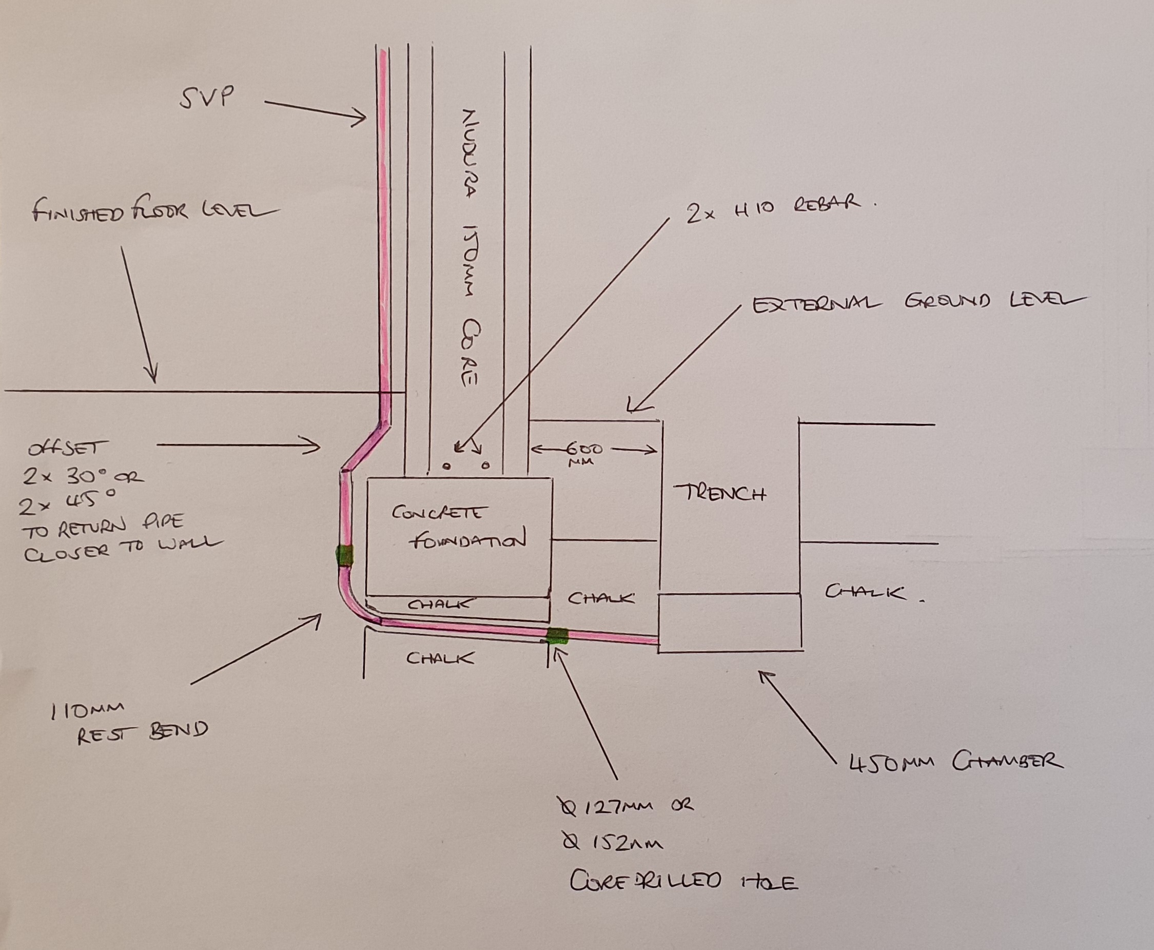
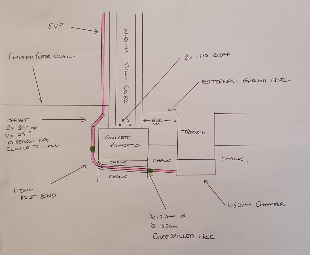
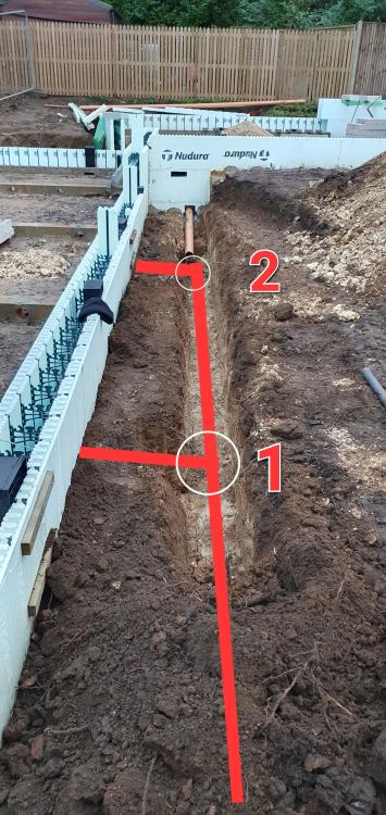
OK, so I've managed to agree a solution that both BCO and SE are happy with. I am going under, I have no practical choice. Apparently, I'm OK because I'm on hard chalk and the perpendicular run of drainage is not within the 'interaction zone', in other words a 45° angle downwards from the bottom of the foundation. My SE recommended a flexible joint on each side of the foundation to be sure. So far, so good. Here's my proposed layout... (this is position 2 on the original photo at the top of this post). I have an SVP that is designed to run up to the upstairs Bathrooms. It needs to be positioned directly on the other side of the wall that we're passing under, so I need a Rest Bend as close as possible to the outside face wall in order the put this SVP in a corner. This means I cannot nicely install a flexible joint between the pipe that passes under the foundation and the Rest Bend because it'll push the Rest Bend so far into the room that I cannot bring it back again in the height I have spare. I can put the flexible joint on top of the Rest Bend, that's apparently acceptable and is shown by the green blobs on this sketch. However, if I bed the foot of the Rest Bend in concrete (which I understand is supposed to be the case?), then this will negate the effect of the inner flexible joint, will it not? Any words of wisdom as to how I can fish myself out of this muckin' fuddle?
-
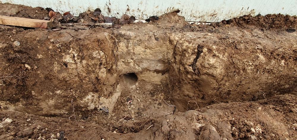
That's a very helpful post, I really appreciate it. Thanks. I've made one of the passes under the foundation. Here you'll see that I've dug down to about 200mm or so under the bottom of the concrete (which is about 400mm thick, spec was 300mm) and bored through solid chalk. I opted to use 127mm which will take the 110mm pipe. Unless anyone here has a better idea, I'm likely to lay all the drainage, including the slope I spoke of (which looks like I can achieve what I need with 22.5° bends) then get the BCO out to check, at that time, I'm hoping we can have a practical conversation about backfill for it all. In the meantime, I'll await a reply from my SE with his opinion on how to deal with the backfill and my method of passing under the foundations. Furthermore, in the grey water run from the Kitchen, am I able to add a T-Piece midway and use the vertical branch to come up in the island? Thanks for all your help so far.
-
In a nutshell, the catalogue of errors in the way the foundations were dug (covered roughly in this post) resulted in some urgent decisions about rectification and a change of plan on concrete heights/volumes etc. Keep in mind that my building has 3 internal level changes and is built on a slope with a height differential of over a metre on both planes from one side/end to the other. Consequently, the decision about 'top of concrete' height has, in my opinion resulted in the concrete being too high, thus passing my pipes over the top in the area shown will result in them only being about 200mm under the soil. I'm not at all comfortable with that. In fact you can see one of the air-bricks and the height of the pipe as it emerges over the foundation to get an idea of the distance we're playing with. Hence I want to get the drainage pipes as low as possible, as soon as possible after we're over the foundation. Make sense? Luckily this all adds up with the onward drainage run which was laid well in advance, in fact it probably prevents the need for a backdrop in the onward chamber.
-
That illustrates perfectly what I want to do. Very helpful indeed. Thanks.
-
As an update to this, both BCO and my SE have said that the drainage run needs to be encased in concrete, owing to the fact that it is less than 1m away from the foundations. Happy days. If I encase the whole thing in concrete, surely that's going to take out any scope for movement in any of the pipe, hence the whole flexible joint thing is nonsense. I had hoped to have my drainage and beam & block inspected at the same time, but this isn't really practical, so I think I'll need to get the drainage all laid and set, then get BCO out, they'll advise what needs concrete and what can have pea shingle, then I can move on. I like bedding pipes into pea shingle, you can fine tune the fall and get it just so, I feel with concrete that's going to be really hard. What can I seat the pipes on that won't get blasted out when the concrete goes in?
-
That's a great opinion. Thanks. I agree that the grey water from the Kitchen will ball in and push the you-know-what's on their way.
-
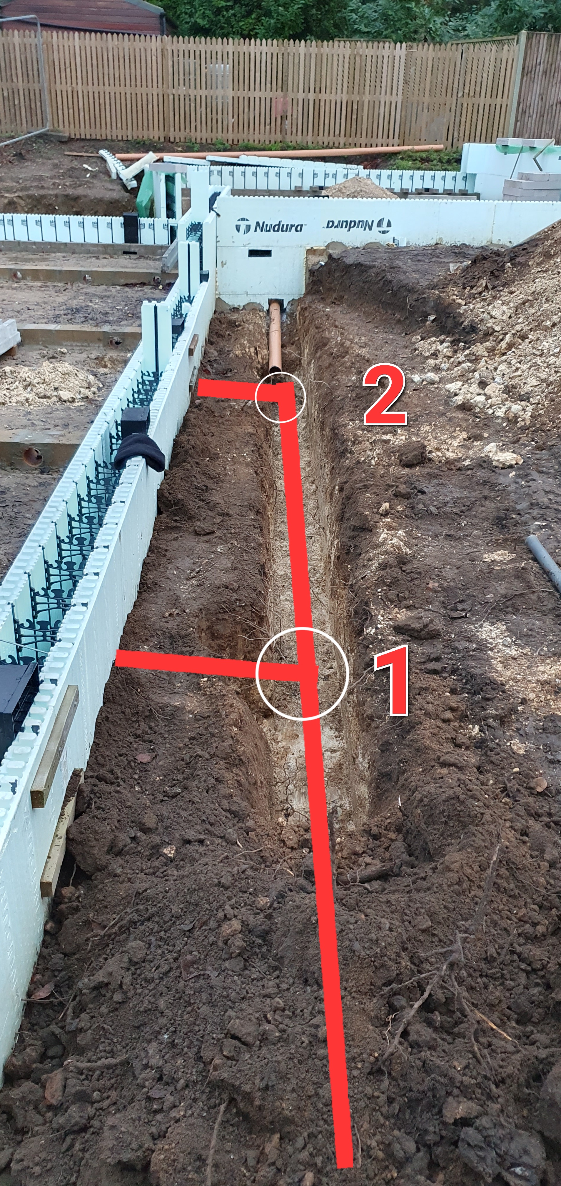
Our build seems to have a fairly simple drainage requirement, well, it would have been had it not been for our foundations f*uck up. I won't go into that now, but the legacy of it results in my having to pass the majority of my drainage under the foundations. Believe me, this is a small price to pay for how deep in the doo-doo we were a few weeks ago. In this image, you'll see a trench partly dug. The red line denotes the main drainage run, heading from far to near. There are 2 chambers denoted by white rings on the pic. I'm happy with the depth of these, they line up with where I need to bore under the foundations (the 2 lines you can see coming into the chambers), more about that later. The majority of the run you see in this pic, including both chambers, deal with 3 Bathrooms and a Utility Room, so in my eyes takes priority. The soil pipe you can see coming in from afar serves ONLY the Kitchen, so no WC's. I really can't put that one under the foundations, it's just too much work there and would be more disruptive than I think worthwhile. Consequently, there is a 500mm height difference between the pipe and the connection point on the next chamber (marked '2') on the pic. That chamber is 2.2m from the wall from which the offending soil pipe emerges, hence I do not want ANOTHER chamber. What's the best way to drop the Kitchen pipe down? Do you think I could get away with 45°/45° or 30°/30° drop just after it's gone over the foundation, a brief downwards ramp if you will, totalling no more than 1.5m and connected straight into the chamber. As far as going under the foundations. We are on hard chalk, which my SE seems to suggest gets me away with a lot of stuff that other ground conditions might not allow (I am awaiting a response from my SE to back up my proposed solution). I'm trenched both sides, to about 200mm below the bottom of concrete. My idea is to core under the foundations and insert a 160mm soil pipe sleeve, then pass the 110mm through that. Any thoughts? Thanks in advance.
-
Detailing Beam and Block - DPM
Mulberry View replied to Mulberry View's topic in Bricklaying, Blockwork & Mortar
Cheers @nod. Ours is an ICF build, so not too much brickwork to do, just internal wall blockwork. -
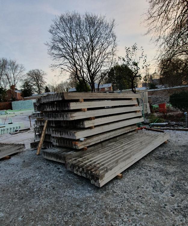
I'm close to getting our concrete floor beams in place. The bearing walls are mostly built and the beams are on site. For the outer perimeter bearing walls, I'm thinking of laying DPM along the full length of the bearing wall, turning up to cover the ends of the beams, then back in on top of the beams/blocks once grouted? So essentially forming a C-shape to encapsulate the beams? I'd have thought 450mm DPM would be sufficient for this? (100mm bearing, 175mm deep beams, 150-175mm left to turn back in?) Presumably the internal sleeper walls where beams meet just need a narrow band of DPM under the beams with no turning up? My sleeper walls are 215mm, so 300mm DPM should more than suffice there. Is anything further needed to protect the cut ends of the beams to protect them from damp?
-
As a further update, our mains drainage application has now been approved also. We're SO pleased. No special requirements (well other than a condition relating to protection of the trees on the route of the drainage, but it's academic because I laid the pipe over a year ago!!). Nutrient Neutrality, or anything pertaining to it, was never mentioned. Good luck everyone else.
-
Nudura - Air Brick Placement...
Mulberry View replied to Mulberry View's topic in General Self Build & DIY Discussion
Thanks @Russell griffiths. I've since started placing the vents according to measurements. Here's what I've done. I took an overall measurement of the wall, allowing 30mm 'overspill' on the length of the wall to account for the return on the slip (23-25mm + 5mm adhesive), then 195mm for the first brick. From there I was able to use 225mm brick gauge to decide on the vent position. I've opted for a vent every 10 bricks, roughly. There are many thoughts on how many vents, but I have several locations where vents are impossible, so I think this placement leaves around 2m between vents and I'm fairly happy with it. Some of my walls were designed with perfect brick gauge spacing (taking into account) the 'overspill', but some aren't quite right, so in those cases, I'm going to gauge from the corners and allow for any cuts to be within a door/window opening so that later on we can decide how to make up the discrepancy. The majority of the visible vents will be nicely spaced, but honestly, the level of thought needed for these in our design is boggling. I was able to space the majority of the vents so as only to need one set of webs cutting, but to make the above spacing miss all the Sleeper walls (essential) and avoid only cutting one set of webs (ideal, but not essential) is just too much. Leaving this here in case it helps someone else. Now I just have to figure out how to plug the vents to stop them collapsing, but with something that can be removed afterwards if we decide to lay the B&B floor before the first pour. Answers on a postcard. -
I'm just planning my Periscope Vents. My design is very complex in terms of levels, so I'm having to really engage my brain to get the heights right on each face of the building. I started wondering if I should be positioning the external vents to line up not only with the coursing of the brick slips, but the horizontal spacing too? Is that too ambitious? What have others done?
-
Beam & Block - Cross Ventilation
Mulberry View replied to Mulberry View's topic in General Self Build & DIY Discussion
Thanks for you help everyone. I have decided to build using the 140mm 7N blocks to a total height of 150mm. Although BC were happy for the cross ventilation to occur via the gaps under the beams over the sleeper walls, this will not work as several are load bearing, so I learn will need to be fully infilled. I've put 110mm soil pipes in as cross-vents at an average of around 1 per metre. These will have around 40-50mm of concrete over the top of them and have been placed as best as possible to avoid a beam bearing positions. I will reinforce over the top of the soil pipes with rebar grooved into the blocks and bedded in the concrete as an additional security (I have a fairly big pile of 10mm rebar in 400mm lengths leftover from the Geocell driveway job, I have no other use for them). Hopefully that's enough. -
Beam & Block - Cross Ventilation
Mulberry View replied to Mulberry View's topic in General Self Build & DIY Discussion
For what reason? Do you mean so that I can build the vents into the sleeper walls? My drainage design is super simple in layout, but sadly it's all got to go in trenches inside the footprint, so there's nothing else to go in the void. As I said in one of my other posts, the drop in void enables me to increase the insulation. Genuine question, why keep the void at 225? -
Beam & Block - Cross Ventilation
Mulberry View replied to Mulberry View's topic in General Self Build & DIY Discussion
Mine at 175mm beams, the base is 75mm deep. That said, I do have an awful lot of beams. 🤣 -
Beam & Block - Cross Ventilation
Mulberry View posted a topic in General Self Build & DIY Discussion
I'm planning a 150mm void under my Beam & Block. Was going to achieve this with 440x215x140 7N dense blocks laid on their backs. This also provides me with a 215mm wide bearing to assist with the narrow beam spacing (so the beams can be laid without clashing). If I lay the sleeper walls in one course as described, how do I provide cross ventilation? Or do the gaps between the beams suffice? -
Drainage help please...
Mulberry View replied to Mulberry View's topic in General Self Build & DIY Discussion
In that location there is no further need than that one Bathroom. I had already felt that connecting other things where a toilet is would be tricky. I do like the idea of being able to decide precise layout later for that room. SWMBO likes the idea of a recessed 'shelf' in the shower, that would need a fairly deep box-in, so it could easily double up with boxing the pipe in as drawn, along with the concealed cistern. I think I'll go with a simple offset to bring the pipe back in, using the shallowest angles needed for the required offset once measured. Thanks. -
Drainage help please...
Mulberry View replied to Mulberry View's topic in General Self Build & DIY Discussion
Thanks again Russell. So, is it good practice to come up through the floor directly beneath a WC then have the Shower/Basin connect into that pipe? My Architect appears to have drawn it as a pipe in a boxed in section in the corner with the WC coming in from one side and the basin/shower from the other. In which case, getting the pipe as close to the wall as possible would reduce the depth of the void. There is a 25mm service void in the plan, I assumed I would increase that one wall to be deep enough to house the 110 pipe, perhaps even deep enough to house a concealed cistern and the shower gubbins for the main downstairs bathroom. I do certainly have an SVP that will need to be close to the wall as it just passes through a downstairs room in order to serve the upstairs bathrooms.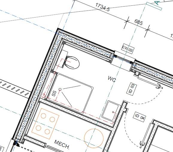
-
Drainage help please...
Mulberry View replied to Mulberry View's topic in General Self Build & DIY Discussion
Another thing, because I'm having to come up alongside and/or under the foundations, my vertical pipes will be around 100-150mm off the wall due to the width of the foundation. Presumably I can fit an offset piece to bring it back to the wall after the foundation? The join would take place mostly in the void I guess. I imagine this will involve either a pair of double socket 45°'s, or a double socket 45° followed by a single socket 45° -
Drainage help please...
Mulberry View replied to Mulberry View's topic in General Self Build & DIY Discussion
The cupboard cap connection situation sounds ideal. I can't see that 110 run ever blocking up before the first chamber, but a 'just in case' solution seems like a good idea. You think BCO will agree with that? Noted on the red line thing. Our foundation c'ock up involved a late change of 'top of concrete' height. I suggested a further 300mm step in the foundations, but my engineer disagreed. Consequently now my foundations are pretty shallow and my soil pipes will be too. The 300mm step I suggested would have prevented this and I cannot see why it wouldn't have worked. To come over the top of the foundations, my pipes would be only about 200-300mm under the topsoil. I don't want to be constantly revealing them in the shrub beds etc, so putting 2-3 of them under the foundations seems like a sensible investment of time and almost unavoidable. My plan would be to trench either side of the concrete strip, then pass under with a long core drill as it'll be through hard chalk. In theory, it doesn't feel like the hardest thing I've ever done. -
Drainage help please...
Mulberry View replied to Mulberry View's topic in General Self Build & DIY Discussion
Presumably I'd then not be able to fit a rest bend at the Kitchen, but would have to instead use a T-piece with the vertical branch taking the Kitchen flow and the horizontal run continuing out of the building towards the rodding eye? Or is there a swept T-piece designed for this purpose?