sharpener
-
Posts
1487 -
Joined
-
Last visited
-
Days Won
1
Everything posted by sharpener
-
You could try a company like Wrekin Water who sell resins and other media for various applications and may well know what charge yr particular softener takes. Also they may be able to suggest/supply a modern unit for less than the £1400!
-
Can't recall. It is a 600 x 1200 K22 if that helps. (If BBOE is the quoted output condition then add 5% for TBOE.) It was a trade-off to avoid having a K33 or one so long it would have overlapped the door frame and looked rubbish. Heat Engineer presentation could be better, so could rad mfrs who all have slight variations. Unfortunately there is no standardised operating condition for rads on HP. If you are using a factor of 1/0.396 that is 2.5x, AFAIR installers used 1.9, can't now remember how that was derived, whether empirically, from rad data tables or raising the ratio of the two mean temps to power of 1.3 which is usually reckoned pretty good and well within other inaccuracies. E.g. installers forgot B1 and B2 have vaulted ceilings, when I pointed this out they fixed one but not the other, in the end I gave up trying to get all the small errors fixed. Was at the time more concerned about getting the electrics installed in a way which integrated with the battery system, met the regs and kept their spark happy, which was not easy to arrive at. As to the main thread am planning some experiments over the w/e and will report back.
-
Leakage or induced pickup from other wiring is a real possibility depending on what the input circuit impedance on the panel is. Might have a pull-up resistor and a proper voltage comparator. Or might just be a CMOS input pin. If product is well-designed it will have some RC network and/or Schmitt trigger input to make it noise proof - ah I see you mention Honeywell so all bets are off. So determine by experiment what value resistor would be recognised as a contact closure i.e. triggers alarm. Then fit resistor 10x this value. Unlikely to fail to danger, in a real "break glass" situation it would be shorted by the switch contacts anyway. OTOH if the switch opens on break glass then I can't see the resistor doing anything at all. This is potentially a better method as it constantly tests the wiring continuity. And a loose terminal screw would cause an intermittent false alarm. So you need to find out which way round it works.
-
PMFJI but the DNO (WPD now NGED) accepted my application for a self-install after a bit of to and fro. So it can be done. Since then they have waived their original restrictions on inverter power and export power as well. And subsequently given permission for an EVCP and a 12kW heat pump. All on an 80A supply, quite a voyage of discovery, the 16 sq mm meter tails do get a bit warm at times.
-
Yes yes and no. At least not in the sense you mean. Before anyone gives the standard advice for HPs to remove the mixing valve and pump, note that I need them when both sets of emitters are operating in order to dilute the hot water at the temp of the rads down to a suitable temp for circulating in the UFH. Otherwise we get back to the original problem which is the UFH return flow is too much and too cold.
-
Yes. Salus ABAs look interesting (see also this thread) but address the wrong problem. They would control the recirculating flow in the manifold post-mixer. I need to control the amount of water from the primary flow into the manifold. Also it needs to be different in the two scenarios, by a factor of 4. Interesting prog on Ch 5 as I write, not too bad as they go with good pointers to BUS.
-
Depends. Cars use ethylene glycol based antifreeze. HPs use either that, or propylene glycol which is markedly different in several of its properties. Fortunately someone has researched this stuff before <g>, it's all in here.
-
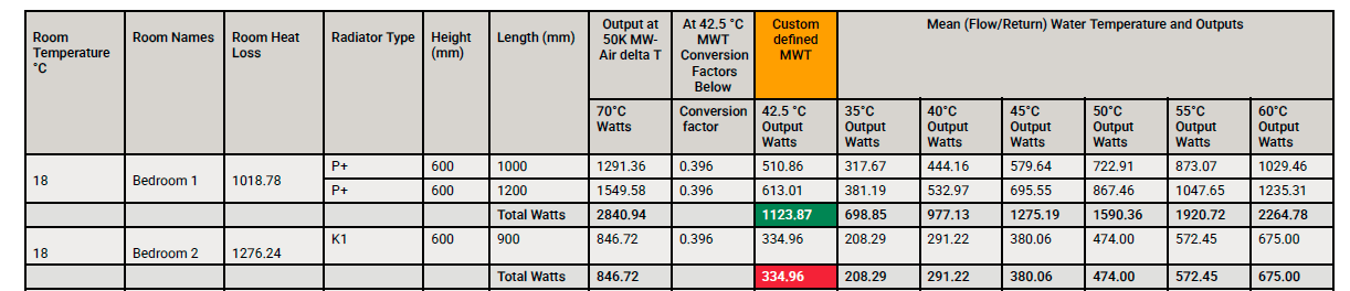
That table was purely to show you how Heat Engineer tabulates the output at various MWTs, to help you scale your rads for a 35C flow temp if you can't get that info from the rad mfr's data sheets. The relative data are what is important, the absolute values less so. No, those were the original rad sizes. B2 is the one they wanted to upgrade to a 600 x 1200 K33 but the compromise was a K22 with TBOE and upping the MWT to 47.5C. The original B2 rad went into the bathroom where there was none at all. Previous owners of the house had some funny ideas, e.g. the rads are mostly on the far side of the rooms from the windows but taking up all the floors to re-site them was too much. Many were too small even with the oil boiler, I put 3 additional ones in before the HP was thought of.
-
Search for the earlier thread "Are all glycols equal" or wtte.
-
It's right on the margin. Normally we get away with using just the two rads in the living room, as neither of us likes the sensation of a warm floor. When we tried it with the oil boiler I think the mixed down flow temp was set at 45 but we certainly wouldn't like it that hot on a regular basis. It's further complicated by ToU tariff as Cosy is cheap from 1 pm to 4, then it goes to peak rate until 7. We are elsewhere earlier in the day so start to heat the room from 3, and after 4 continue to run the rads from the thermal store (which runs down from a 50C starting point) as we want the room up to temp by 5 o/c. But in the recent cold snap the rads were not enough and adding the UFH as currently configured did not help as it pulled down the flow temp. So the aim now is to avoid that and at least have enough heat from the UFH to prevent heat loss through the floor, I think that will do it. You might think it would be sufficient to run one or the other, but the UFH thermostats click on and off every 30 mins or so in the equilibrium state so the time constants involved are surprisingly short.
-
Yes and no. I used the free heatpunk s/w to make my own estimates of the whole house heat loss to confirm HP size. The room-by-room estimates were then done in detail by the three potential installers as part of their MCS approved quotations. All used Heat Engineer (IIRC you can buy a one-project licence for a reasonable fee but the learning curve looked too steep). They all quoted figures at a range of temperatures. Here is one extract: This doesn't quite cover your case, but without reverse engineering it all I think you would get a close result by using an exponent of 1.3 to work from published 50C dT rad outputs. Certainly it would work for the small correction from the figures tabulated above for 35 to get to your 32.5C MWT. All assuming that the scale factors are independent of actual physical rad sizes but I think that is reasonable. I think you would struggle to get a working rad flow temp as low as 35 though without ending up with a lot of K3s. Our oil boiler had been set to 65C, and at 50C flow we only just avoided using any, the average rad size upgrade factor was 1.9. The installer wanted to fit one in B2 but I persuaded him the 5% increase in output from plumbing a K22 as TBOE was sufficient. Even so there was a subsequent iteration to get the sizes down by increasing the MWT to 47.5. Of course all these figures are for worst case OAT (-0.2C, Plymouth), using the WC we expect them to be much lower most days.

-
Yes Problem here is that reducing the dT between MWT and room from 27.5 to 12.5 means the rad output is more than halved bc of the 1.3 exponent in output vs dT, so is reduced by a factor of 2.79 or to 36%. This is a big drop and wouldn't meet the heat loss of the room as per my last post. So as stated I think it is worth experimenting with the existing valve setup first before making any permanent changes to the plumbing.
-
Not necessarily, you can programme it over the LAN using a local IP address. Then it will run without reference to the web. Only mentioned it as is surplus to another project, not worth the hassle to get a £17 refund, I am sure it will come in handy for something. They installed to my spec and did a good job within various constraints including re-using the existing cyl and UFH and the wiring betweeen these and the utility room. Nor can either of us know what exactly is under the floor from 1995. Anyway, before asking them back I want to understand how the combo of rads and UFH works in theory, and what might be possible in practice. Which is why I started this thread before these or any installers were on the scene. I hope I have shown the much-discussed use of rads and UFH in the same HP system is more complicated to optimise than many ppl think. Maybe motorised mixers like Esbe are the answer but I am not convinced there is any thermodynamic advantage and the time, expense and disruption to install is unappealing. There are four circuits each with their own wall-mounted thermostat Living Rm E, ~ 25 sq m, important as it is our main sitting area. There is also a rad rated at 1150W @ 47.5C Living Rm W, ~ 25 sq m, not used as there is a raised dais limiting heat flow, and a piano. There is also a rad rated at 1150W @ 47.5C Installers' estimates for the whole room: heat loss 3653W, output from UFH 5321W @ 40C flow. I have no idea where they got that from, @JohnMo's nomogram upthread gives 46W/sq m for a MWT of 37.5C which implies more like 2300W, so would need half of that plus both rads to meet the heat loss of the room. Hall, ~ 15 sq m, needed to take chill off hall at least. Manifold is here in cupboard under stairs. Front door and side panels are d/g and well draught-proofed (apart from the keyhole!) but still make it cold. Kitchen E, ~ 15 sq m, needed as the AGA is at the opposite end.
-
Yes they are physically separate with their own zone valves. But as upthread the HP controller will cause the flow temp to suit whichever is the higher. So when the rads are in use I only want to allow a small amount of flow to the UFH. At other times a larger flow at a lower temp and better CoP. No, we upgraded 6 out of the 8 when the HP was installed, they should all be quite well matched now. Current plan is to restrict the flow to the UFH by partly closing the isolating valve, and then see if the pump is sufficiently powerful to push more flow through it to the UFH when the rads are not on. The Wilo internal pump in the Vaillant HP generates a high head and will try and do 34 l/min under most circs. If this does not work well enough I will just set the times so they do not overlap as you suggested earlier, until the heating season is over and I can cut into the pipework to install the bypass valve round the flow restrictor. Am still thinking how to do this without running more cable from utility room to the UFH manifold. Yes I have a spare Shelly plug so might do it wirelessly.
-
I think the heat losses are too much for "either or" to work unfortunately. In the recent cold snap the HP needed to work at max o/p much of the time. The hall and the end of the kitchen furthest from the AGA got very cold without the UFH, and I had not at the time worked out why the UFH crippled the output from the rads. Living room has both so it matters less there. We do have the system divided into the two zones but the flow temp from the HP is determined by the heat curve for the higher of the two emitter circuits, so if there is any demand from the rads side it will run up automatically to the higher temp. Not sure how I could prevent that. Perhaps use the microswitch contacts on the UFH zone valve to do something cunning like open the rads zone valve without the HP controls knowing! I still think I would need to modulate the flow rate to the UFH though.
-
Have you condidered paying a Quantity Surveyor to give you some comparative figures? They have access to a regularly updated database of common construction elements. FWIW I have a house with similar wall construction and the radiator sizes for 47.5C av temperature are manageable. If you have an existing suspended timber floor without any ventilation of the cavity below have you lifted some boards to see if the joists are in good condition? IME in a (different) terraced Victorian cottage, even with airbricks front and back there was quite a lot of damp and consequent rot particularly near the party walls.
-
Well it gets more complicated by the day! The flow limit of 4 l/min to the UFH is required while the radiators are operating as described above. But when they are not, I realise I need to be able to supply the UFH at a higher flow rate and lower temperature, say 35 deg, in order to achieve a correspondingly higher CoP. Perhaps when there is no flow to the rad circuit the internal pump in the outdoor unit will be powerful enough to get sufficient flow through a fixed restriction like a partially closed valve as upthread - I will certainly check this out first. Otherwise the flow restrictor will need to be bypassed when there is no demand signal for the rads. Fortunately I have a spare motorised valve which can be supplied via the n/c contacts on the rad circuit zone valve which should achieve this nicely.
-
Thanks. The primary valve (a) in Fig 3 looks to be the one to control the overall flow from the HP. I think my existing manifold has an equivalent so I will try it. There is also a motorised valve in the return pipe (was easier for them to fit there as all rather cramped), and a manual 22mm iso valve in the flow. If there is room downstream to get in a 22mm flow setter I might do that so I can see flow rate. If no room I could alternatively replace the iso valve with a ball valve/flow regulator like this with a 4 lpm insert. The mixing valve is suspect anyway and unfortunately I have not been able to trace the original part or find a replacement with the same porting, so it will need some complicated pipe-fitting in a restricted space, a job for summertime I think. If I do need to replace it then I could instead buy the whole Invar caboodle. After checking it will fit my manifold! £158.82 is not a lot considering what you get for it.
-
Sounds ideal, have you got a link? I have found lots of Ivar valves on the web but am struggling to find one that matches this description. dT won't be 20. Assuming 12.9 l/min of return water mixed with 4.3 at 50 straight off the HP this gives 35 into the UFH and 30 out. So not much variation along the loops and I hope reasonably uniform floor temps. Will do some further calcs using the nomograms upthread which you helpfully provided @JohnMo. Under the HP install contract most of them were uprated by 1.9x size factor already, so as to get the output I need at only 47.5 mean temp instead of 65 from oil boiler. One still in good condition was repurposed as a bathroom rad.
-
Yes it sounds like the thing to do but you would need shunt bypass circuits or ABVs to maintain the flow when there was no demand from either half. And with such vast differences in the desired flow rates control would still not be easy (as I have found!). Have thought a bit about the thermodynamics of it and I don't think there would be any advantage. If you need a higher temp for the rads then that is what will restrict the CoP however the system is piped.
-
I have had some trouble setting up the flows and temps on my UFH manifold - the cold return from the UFH prevents the HP attaining the desired 50C flow to the rads when it is very cold outside. So I thought I would visit this topic again. Setup is a Vaillant 12kW Arotherm plus which has a design delta T of 5C at its full flow rate of 2040 l/hr. I want to split the output equally, 6kW into the UFH (ground floor) and 6kW into the rads (ground and first floors). Design condition for the rads is 50C flow 45C ret at an OAT of -0.2C (Plymouth). UFH dates from barn conversion done by others in 1995 so I do not have any design data. There is the usual mechanical thermostatic mixing valve to vary the proportion of return flow recirculated, and a secondary pump. Q1: How much flow do we need to allow into the UFH system? By calculation (from 1 kWh = 860 litre-degrees), with an available flow temp of 50 and assuming a return from the UFH of 30C, to dissipate 6kW requires a flow of 6 x 860 / 20 = 258 litres/hour or just 4.3 l/min. Note this is independent of whether or how much water is recirculated in the UFH loops by the pump/mixing valve, the heat given up depends only on the delta T and flow rate. I am not confident that the mixing valve will control this and think partially closing the isolating valve for the UFH circuit will be necessary - at least until I can drain it down and fit a flow setter. Q2: What is the actual return temp from the rad circuit? Actual flow rate will be (34 - 4.3) = 29.7 l/min so temp drop for 6kW is 6 x 860 /(29.7 x 60) = 2.895 deg so return is at 47.1C Q3: What happens when the two return flows mix on the way back to the HP? We get a mixed down temp of ((29.7 x 47.1) + (4.3 x 30)) / 34 = 44.94C so the HP will reheat it to almost exactly the 50C flow we started with. Note that increasing the flow to the UFH beyond 4.3 l/min will result in a lower return temp to the HP so it will not be able to reheat it to 50C any more. Q4: How do I set the mixing valve and secondary circulation through the UFH loops? If there is no recirculation at all then the temp at the start of the loop will be 50C and it will decay exponentialy along the length so giving a very uneven heat distribution also the initial temp may be too high for the floor covering (carpet) so to achieve say 35C at the start of the loop and hence 1/4 of the delta T we need to circulate 4x as much flow in total i.e. 17.2 l/min, so need to add 12.9 l/min from the return side via the mixing valve setting the mixing valve to 35C should achieve this. Fortunately it is not a critical parameter. individual loops can then be balanced as usual at the manifold on the basis of floor area Conclusions (which I will need to test by experiment in the next cold snap): UFH circuit needs much less of the flow than I suspect has been the case I will need to control this separately as it can't be done with the mixing valve setting If there is too much flow to the UFH then the HP will not be able to achieve the required flow temp to the rads Thanks to @Dan F for his contributions offline.
-
Glad you fixed it. Out of interest what was the part no and where did you get it from? The secret is a good de-soldering gun (solder sucker), I only have a manual one which IIRC came from a firm I worked for at one point, the professionals now use ones with a little vacuum pump that runs continuously. The £35 made me wince a bit having just repaired some tricky broken wires inside my son's digital alarm clock. Now I know the going rate I can bargain with him for fun and profit. Previously his teacher g/f's hair curlers needed a new ballast resistor, the school science technician had had a go and made it a lot worse by stripping the track off the pcb.
-
BUS Grant requirements (conflicting info)
sharpener replied to Rudski's topic in Air Source Heat Pumps (ASHP)
Defrost cycle is a different beast from frost protection. You still need glycol or antifreeze valves for that unless you have a totally reliable electricity supply inc. some kind of backup against power cuts, even then you might be unlucky and have a compressor breakdown when you least want it. IME it can get very cold in E Anglia when the wind is in the East, no shelter from hills anywhere nearer than the Urals. -
I put the Evohome system into Holiday mode which turns all the room temperature eTRV settings to 10C. So far the max/min thermometers show that has not got that low. If I know the return date I can enter that too. Only real benefit is that it saves wear on the valves and prolongs battery life. Then the HP gets set to Absence mode so turns everything off except for frost protection. I can use the app to turn it back on before I return. If that is earlier than expected (as above) I can still have HW on arrival. If I remember I do various tricks so as not to leave a HW cyl and thermal store full at 55C which will go to waste. But these addtional complications run the risk that some vital step gets omitted! If all else fails the anti-frost valves will I hope save me from a very expensive freeze-up.
-
BUS Grant requirements (conflicting info)
sharpener replied to Rudski's topic in Air Source Heat Pumps (ASHP)
Several things occur to me here.. Depends on upstairs floor construction. Ours has no insulation, bedrooms get to about 16C without the rads on but even so I wouldn't want to be without them entirely. I have some sympathy with the argument that if public money is involved then the installation should be generally suitable for the property rather than idiosyncratic. E.g. HW cyl should be adequate wrt # of bedrooms. Subsequent owners will after all not be able to get a second BUS grant. If you are going to fit rads upstairs its hardly worth penny pinching on the size at the expense of flow temp as that will hit CoP. I never fully bottomed out what MCS/BRs actually allow but installers won't IME go above 50C flow so the R290 argument is largely irrelevant. I see Cool Energy are now doing an umbrella scheme, their products have not been mentioned on here for a bit but I thought they were well engineered and were quite responsive when I contacted them a while back, might be worth exploring.