Nelliekins
-
Posts
157 -
Joined
-
Last visited
-
Days Won
3
Everything posted by Nelliekins
-
Heating system for an ICF house with UFH
Nelliekins replied to Nelliekins's topic in Other Heating Systems
I assumed the PHE flow would tee off the vent connection right at the top of the cylinder, next to the immersion port. The boiler would connect to the direct ports (top and bottom) on the opposite side of the tank to the coil ports. So would I tee the PHE return with the boiler return, or add a new flanged fitting at the bottom for the PHE return? Do you agree with @PeterW that the UFH buffer is probably not needed, and I can simply heat via the coil? Or am I better with a separate buffer tank, if only so I can use another immersion to assist with initial heating of the UFH? -
Heating system for an ICF house with UFH
Nelliekins replied to Nelliekins's topic in Other Heating Systems
Hmmm you have got me wondering now! There is definitely 2 for coil, 2 on opposite side (top and bottom) and vent out at top. Roger wilko. I have CPC account(s) and frequently pop into the sales counter to grab bits and pieces. I get 3 sets of mailshots every weekend ? There are a couple of brass models sold by CPC - one is AC and one DC. Failing that, BES sell brass ones as well. -
"Hi-ho, hi-ho, it's off to work we go"
Nelliekins commented on Nelliekins's blog entry in Clancutt Lodge
I agree on the risk front, although we had boreholes performed across site and a mining desk study performed to assess ground stability. Odd that you think the space created is worth less than above ground... We have had a number of valuations performed, both before and after construction, and it comes out as adding more value than a 3rd floor above ground every time? We wanted a decent sized cinema room, so a basement is perfect for our needs. Light control, and much better sound insulation than we would ever achieve above ground. We have got 9' ceilings though - rather higher than the average cellar! -
Heating system for an ICF house with UFH
Nelliekins replied to Nelliekins's topic in Other Heating Systems
Private joke? So something like this? -
"Hi-ho, hi-ho, it's off to work we go"
Nelliekins commented on Nelliekins's blog entry in Clancutt Lodge
Truth be told, it's about equal to cost of above ground on this build. It would have been cheaper by about 20% going off our original costings, but for a massive cock up by me not checking what one of our so-called experts did when starting out one of the basement walls... <spoiler alert> ... As a consequence of which, we had a well-concealed but considerable leak in the basement that has led to internal tanking and a bunch of other remedial measures. </spoiler alert> Anyway, more of that to come in the next couple of days (well, the next 9 months of blog time!) ? -
Heating system for an ICF house with UFH
Nelliekins replied to Nelliekins's topic in Other Heating Systems
It's a little under 300m2 across the 3 floors. Yeah me too. There are 3 left out here: - 1 kitchen loop because I ran 3 loops with longest being 103m length, instead of 4 with longest being 80m. - 1 landing loop, because it already has 12 loops in the floor for the other parts of upstairs - 1 laundry loop, ditto Sounds good. Will grab the manual when I go to site next and look at the servicing drawings to check about the boiler pump (or lack thereof) I don't have the flow switch yet - that's next on my list of purchases once I identify the correct model. I would indeed be fitting a PRV as mentioned way back near the top of the thread - it's not on the drawing yet though! Yeah that's my bad. The plan was always to use the cylinder like a heat bank, and a PHE to provide mains pressure hot water. -
Heating system for an ICF house with UFH
Nelliekins replied to Nelliekins's topic in Other Heating Systems
No, it has 2 for coil, 2 for top/bottom heat/return and 1 for overflow. I would have to tee the bottom fitting (not the coil, obviously) or fit a new flanged fitting. -
Heating system for an ICF house with UFH
Nelliekins replied to Nelliekins's topic in Other Heating Systems
The biggest one I can see is that the flow into the manifolds would be too warm unless we get really lucky on a combination of flow rate and coil efficiency. By separating the two into their own cylinders i can have whatever temp I like in both at all times. It's 16mm PEX-Al-PEX, 2.2km over 3 manifolds and 28 loops. Basement manifold has 6 loops set in concrete. Ground floor manifold has 12 loops set in concrete. First floor has 10 loops set in EPS70 (sat in top of router'd 50mm panels) with 18mm chipboard going over. -
Heating system for an ICF house with UFH
Nelliekins replied to Nelliekins's topic in Other Heating Systems
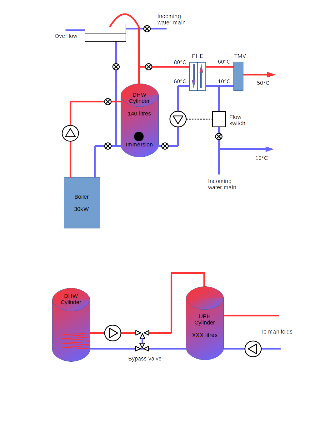
Hi Peter. I did most of this in the PDF included in the OP. Here's a better labeled PNG version... Please excuse the lack of correct symbol for the bypass valve! ? FYI, the "DHW Cylinder" shown on both parts of the drawing are the same cylinder - the drawing was simply drawn as 2 separate diagrams to explain it to a mate! I'll have to check re the coil capacity, but that coil only has to cope with (part of) the UFH load anyway. Regarding the boiler capacity, I would assume that since we are heating the DHW cylinder directly (ie not using the coil), we can get the full beans out of the boiler, i.e. 30kW give or take. I would expect 30kW to be more than enough to drive 2 showers, would you agree? If the DHW cylinder only copes with with the DHW demand at peak but not the leeched UFH demand as well, it doesn't matter one jot. This is because a 15 minute hiatus for the UFH will have near-zero impact on the house or floor temperature anyway. It's no different than a combi boiler that can only do DHW or CH, but not both... but the fabric of the house and the "constant running" of the UFH heating system makes the effects of the switch from UFH to DHW undetectable to the occupants (I think!), because of the inherent/latent heat capacity of the fabric. Remember also that if we used the same style of (el cheapo) cylinder for the UFH buffer tank, that too would have an immersion port if it were needed, which would be able to supplement / replace the leeching of heat from the DHW tank (and completely separate the 2 systems if that were desirable). That would also free up the DHW coil for uplift of the DHW incoming mains water, potentially (although I suspect there is then the risk that the cold mains gets heated well above 50C if left standing in the coil - so maybe that's a stupid idea, cos the TMV won't work!)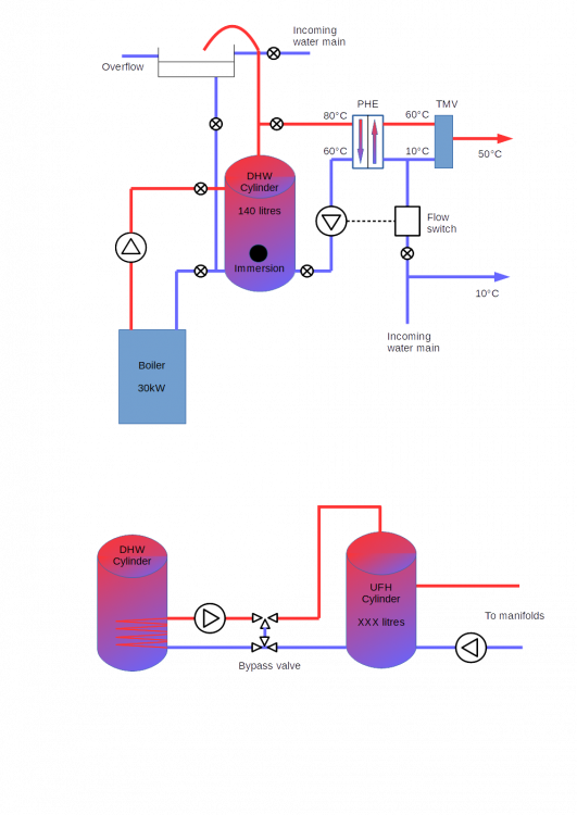
-
Heating system for an ICF house with UFH
Nelliekins replied to Nelliekins's topic in Other Heating Systems
TBH we won't know until we are in the house with it heated. If that proves to be the case, @PeterW's idea of 3 port diverter valves on each manifold would allow us to achieve a lower upstairs temp too. As mentioned previously, my wife appears to be one of the alien characters from the TV show "V", so bedrooms at same temp might be the minimum I get away with! ? -
Heating system for an ICF house with UFH
Nelliekins replied to Nelliekins's topic in Other Heating Systems
Now see that's the kind of thinking I like. ? I presume this would work using the original design of the buffer tank leeching heat via the coil from the DHW system, too. A question then - would this still facilitate distribution of solar gain heat from the kitchen to the entire house, or only the ground floor? I guess the answer is actually down to how well the valves are controlled in this situation. -
Heating system for an ICF house with UFH
Nelliekins replied to Nelliekins's topic in Other Heating Systems
The big difference here is that you don't appear to be keeping everywhere at the same temp 24/7. You are using zoning and there are times when you have rooms that aren't up to temp... Our desired approach (I think) is to have everywhere at the same temp constantly, which means there are only VERY infrequent times when we are present that anywhere is noticeably having to heat up (maybe twice a year, if we turn the system down - but still not off - whilst on holiday). -
"Hi-ho, hi-ho, it's off to work we go"
Nelliekins commented on Nelliekins's blog entry in Clancutt Lodge
Clay all the way, baby! ? To be fair though, Building control looked at the borehole records we had prepared and said if it weren't for the 27m high poplar trees at the front of the plot, they'd have said the ground at 1m down was good enough to build our house off of. Mind you, we would have had to duck down a bit to get in the basement if that was the case! ? -
Heating system for an ICF house with UFH
Nelliekins replied to Nelliekins's topic in Other Heating Systems
Which is why on the drawing in the OP, the UFH was leeching heat from the DHW tank via the coil. Thus the DHW cylinder was being kept very warm (75C), and the UFH cylinder would draw some of that off when needed, using the coil. The upshot is that the gas boiler gets nice long burns (maybe 5-10 minutes?) to reheat the DHW cylinder to avoid short cycling and to not have to modulate much (or at all) when it does so (although that depends on what the minimum and maximum temps for the DHW cylinder are to still deliver the right water temp from the PHE output. Each circuit has a flow meter on the top, and a zone port that can take a valve at the bottom. Adjusting either top or bottom controls the flow rate through that circuit, so adjusting all 6/12 flow meters (depending on which manifold we are talking about) therefore dictates overall flow rate through that manifold's outputs. I can do that, no problem. However the differential between flow and floor temps is only a few degrees C, and the buffer tank water is to be held at ideal temp for distribution, so under what conditions do we need to stop the flow, beyond what would be achieved by simply turning off the pump (which we don't want to do much anyway)? That is fine. If we revert to the design in the OP, we have : - A 140L cylinder, which you suggested yourself would be adequate for our peak DHW usage scenario of 2 showers, provided the boiler can replenish it quickly enough - a 30kW boiler dumping heat into the 140L cylinder directly (so maximum efficiency, apart from possibly too high a cylinder temp?) - the 140L cylinder receiving a boost from a PV-powered immersion during daylight hours, so no gas burn unless the cylinder is drained faster than the PV immersion can replenish, and the cylinder allows us to extend the PV regen time because it will still work within a temperature range (ie if the heat is taken out by a tap running for 1 minute, the immersion can take 20 minutes to replenish that energy, because the cylinder might have dropped 2C but it operates properly in a possible 15C range before needing additional heat anyway) - the 140L cylinder supplying heat from the top outlet to a PHE to give DHW via a TMV to a hot water manifold (which has 22mm outlets for bath and showers, and 10/15mm outlets for sinks) - separate UFH buffer tank heated by PV-powered immersion and the bottom-mounted coil from the DHW cylinder (at a flow rate TBD to ensure the low temp for the UFH is maintained in the UFH buffer tank). Here the pump for the DHW coil - > UFH buffer can run at whichever flow rate is necessary to control the heat energy being delivered to the UFH buffer (and the home automation can control the on/off side simply enough provided it knows the flow and return temps and the cylinder temp(s) as well) The DHW cylinder takes maybe 10-15 minutes to fully replenish from the gas boiler (except it'll never get fully cold, and the boiler will hopefully be able to inject heat as fast as it is taken out if 2 showers are running so they never run cold). That sort of lag on the UFH side of things is inconsequential anyway - I doubt we could even measure the temp drop that occurs in 15m if the floor is at equilibrium. As I say, that (probably not full) replenishment will only take place when there is a big drain on the DHW, eg running showers or baths, or a number of smaller drains (several lots of sink usage). Running a sink tap should only result in a small topup being needed, which will either come immediately from the PV immersion or get held back until the cylinder needs a bigger boost (eg at night) at which point the gas boiler does a single longer burn again. So maybe we don't bother trying. If we follow and extend @JSHarris' design, the 3 manifolds receive water from a UFH buffer tank held at the desired flow temp to eventually achieve the desired floor temp. It doesn't matter if the lag on the first floor (where the pipes are only 20mm below the surface) is less or more than the concrete floors below (where the pipes are 75mm below) - at some point all floors will achieve equilibrium and stop extracting heat from the pumped water. There may be a case that we don't want the upstairs floor to get as warm, if the EPC guy was right. But that's a whole different ballgame, and even then if we know the temp in the upstairs floor, we can simply shut off the 2-port valve supplying the manifold that you have recommended we install, to avoid an overshoot, yes? Which leaves us with what seems to me to be a potentially workable solution that doesn't stress the gas boiler unduly (although i agree it could be improved considerably by the use of a Sunamp to allow the boiler temp to drop a bit) and has more than desirable heat losses because of the F&E tank (which also would be addressed by the use of a Sunamp) -
This was a hobbit-hole, and that means comfort.
Nelliekins commented on Nelliekins's blog entry in Clancutt Lodge
Yeah, our 600m2 plot is a wee bit smaller than that! We felled just 6 trees, and the logs covered a good 1/4 of our plot for a week! -
Heating system for an ICF house with UFH
Nelliekins replied to Nelliekins's topic in Other Heating Systems
One question then - can't we compensate, and achieve the variation in flow rate, by simply tweaking the flow meter settings on each circuit of the upstairs manifold? Whilst the UFH is router'd into the EPS (with no spreader plates), sooner or later the heat in the floor achieves equilibrium no matter what. The EPS and chipboard would have to be perfect insulators to prevent it, and neither come close to being a perfect insulator! Whilst there are legitimate issues that you have identified in getting up to temperature initially (e.g. the lack of conductor to distribute the heat evenly across the floorboard), that's hopefully a one-time problem (or at least, few enough times during the lifespan of the heating system to not be worth additional expense or contemplation). Is that fair to say? Remember also that the target floor temperature is only 22.6C, and to achieve that temp, we are likely to have a flow temp of 27C or less. -
Ok, so maybe I got a bit ahead of myself again... The second wagon that they filled with spoil didn't fare as well. Matter of fact, it managed to beach itself on every axle: The muck-away company had to send a 2nd wagon, fully loaded with 6F2 and a big-arsed chain. Then it dragged the beached wagon out across the street using the chain. The (now-freed) wagon drove off with our load of spoil. Since there was a load of crusher run on the rescue bus, we had it tipped on the front of the plot, to stabilise the ground and prevent a recurrence. So, excavation continued apace for the next few days. Apart from a few more land drains excavated (including an abandoned rat nest), things went well. Here's a few more pics for your delectation: We decided on a stepped bank initially, to try and prevent bank collapse: But as this photo shows, we were still fighting the effects of the bad weather - some small cave-ins, and we started adding acrows to shore up parts of the banks: Now, when we started investigating the options for basement excavation, we had previously considered sheet piling the excavation. However the 2 quotes we received both sad that the steel sheets would need to be left in the ground ("sacrificial" was the word used) because the sheets wouldn't be able to be extracted. And with quotes coming in at over £60k for the sheet-piled excavation, it was well over our budget. So when the groundworkers told me that the excavator was starting to fall into the excavation, and we needed to sheet-pile the front of the hole, I was more than a little concerned. Still, it appeared to work: So the hole was finished - only 74 wagons of spoil taken away... Concrete blinding was laid oversite to stabilise the clay underfoot, and the shuttering for the slab constructed. Then the mesh and starter bars were set into place, and we were ready for the slab to be poured: And lo, our first concrete pour arrived - the first of many! And before I knew what was happening, the slab was done (notice the increase in the number of props / acrows): Time for some ICF...
-
Our groundworkers broke ground on October 9th 2017. Here's the digger and fuel bowser arriving: Bit of a squeeze, but they got it on-site in the end! The driver set to work on the site strip right away. He'd been working for perhaps 45 minutes, when work ground to a halt... A land drain was exposed (well, kind of dug up, if truth be told), in the middle of the plot, all of 6" below the ground. The digger had removed a 2' section of it completely, as this photo shows nicely: Oh well, can't have been that important! ? So the scrape is completed, with vegetation separated off from topsoil. Here's our mountain of topsoil (about 20m3), ready for when we want to spread it back over our garden (and me, feeling all smug about the progress we're making in the space of a day!) And the vegetation... well that was loaded by the excavator onto a 32T wagon. Now we had already arranged for pre-acceptance of our clay spoil at a quarry/landfill about 2 miles away, so the driver says "it'll be fine". 30 minutes later, the driver is on the phone, saying "I'm trying somewhere else - they wouldn't take it here". Another 40 minutes, and another call... "I am off to another place"...and so on. So roughly 4 hours later, the wagon arrives back at site. Still full of the vegetation. "Nowhere will take it", says the driver. "It's because of the roots in the load", says the driver. Turns out, the driver has given my vegetation a tour of the North West, having been to 3 separate counties with it. I'm fairly sure he just took a fancy to it, and they went on a drive in the country... he probably bought it a cream tea in Blackpool and asked it back to his place... Here's the wagon in question: Still, could have been worse... the groundworkers pulled a magic trick out of their hat. They dug a Transit-sized hole out of the bottom of the plot, and dropped the vegetation into the hole. Then they loaded the spoil dug out of the hole onto the wagon, and that was accepted at the quarry. The groundworkers compacted the vegetation, put a 600mm capping layer of clay over, and job done. Pretty successful day, if you ask me!
-
Waiting isn't something I am known for. Waiting nearly 3 months, for these mythical birds to vacate the invisible nest isn't going to happen. 4 weeks later and we're into July, and I've had enough. Here's what was left of the hedgerow, along with my weapon du jour. As it happens, there was no nest in the hedgerow. Probably because the houses all around have cats that hunt, and even birds aren't stupid enough to nest 4 feet off the ground when there are dozens of suitable nesting places in the trees on both sides of the street! The closest thing I found to a nest was a 20-year-old gin bottle, filled with cobwebs. We also chopped down about 50m2 of brambles and a few western red cedar that were in the middle of the plot. Then we put a bit of Heras-style fencing around. So now, our site looked a lot cleaner and larger: But we had still waited too long. The firm we had verbally accepted a quote for the groundworks from had moved onto a large new job, and wouldn't be able to return to our project until the new year. ? Time to find some new groundworkers... should be simple enough, right? Wrong. A big contractor had just pulled out of a major development project a few miles away, so every groundworks company within 20 miles had been signed up to take up the slack. We looked at everyone from "one man with a digger" to big national outfits, but nobody was able to take the job on. Until we found this company, based in Liverpool. Smallish outfit of about 15 men and a couple of decent-sized machines, including a shiny new 13 tonne excavator. After some to-ing and fro-ing, we decided to take them on, on a day rate basis. Planning passed (way after the expected date, but that's nothing new with our LPA apparently) - both applications. So Kim chose the big kitchen layout. But before we could break ground, we needed structural calcs done, and that meant an engineer! After ringing around quite a bit, we found a local firm that were happy to take the job on. They didn't have much ICF experience, but I figured that it wouldn't really matter. How wrong I was... This engineer started off on the right track, working out slab details from the borehole results, etc, etc. Then it came to the ICF lintel and column calculations. Now, the new kitchen design incorporated some 6m-wide bifold doors across the back of the house, with 1m-wide columns either side of the bifolds. We had picked Logix as our ICF product of choice (primarily price driven, but also because we could have thicker external wall insulation, which would improve our thermal performance considerably). The Logix blocks were 406mm high, and had plastic webs for supporting horizontal rebar at roughly 1/4 and 3/4 of the height of the block. Here's a pic: So far so good. Except our engineer had decided that the steel would be placed every 150mm vertically in the wall for the columns either side of the bifolds. Now, for the layperson, I'll point out why that doesn't work. Here's the list of positions for the steel vertically, in mm: - 150, 300, 450, 600, 750, 900, 1050, 1200, 1350, 1500, 1650, 1800, 1950, 2100, 2250, 2400, 2550, 2700 Now here are the positions where the rebar is supposed to sit: - 100, 303, 506, 709, 912, 1115, 1318, 1521, 1724, 1927, 2130, 2333, 2536, 2739 Notice the numbers in BOLD in both lists? That's where the web would physically get in the way of the steel rebar. Cutting the webs would destroy their structural integrity completely, and mean you have to find alternative ways of bracing the ICF wall blocks - which would be possible if they weren't corner blocks. Which they were. I pointed this out to the SE. He said I didn't know what I was talking about. So I had my ICF expert builder (who agreed with me about not cutting those webs) come and chat with the SE, and explain the same thing. The SE smiled, and said that it would be fine. So I had the ICF block manufacturers (who also agreed with me about not cutting those webs) ring and email the SE. The next thing I know, the SE has emailed me, saying (and I quote, here); The fact that we couldn't use his designs, because they were inherently unworkable, was the problem in the first place! Lesson learned - do NOT engage a structural engineer who doesn't have experience with ICF when you're building an ICF house. 8 weeks we had been working with this engineer, and all for nowt. Phoned a couple of ICF manufacturers for recommendations for an SE with ICF experience - there was 1 common name on the 2 lists I received back. I phoned him, and accepted his quote the same day. 4 days (not weeks) later, I had the calcs in my Inbox, and an invoice to be paid. The steel was in the right places for the blocks we were using, and we even had little detailed drawings showing how to tie the lintel links to the main rebar, and where we had to put what types of welds & bolts to bring everything together properly. Maybe our fortune was changing for the better at last...?
-
Preparing the documents for the planning application was simple enough. We paid a nice man to come and prepare an "arboricultural impact assessment". Basically, he looked at what trees were on and around site, asked which we'd like to keep, and went away. 3 days later a nice 22 page report appeared, and remarkably it said good things about only the trees we had expressed fondness for. Then another nice man came around and dug very narrow, but very deep holes in a few places on site. Here's a photo of his contraption: The boreholes only went down just over 6m, because we were having a basement rather than a well. Still we got fairly good results - the clay was stupendously stiff. At one point we had the borehole man (who didn't want his photo taken) and myself hanging off the lever arm, trying to withdraw the thing from the ground! ? So, we submitted our application. Job done, I thought. A week came and went, and we had a nice sunny day, so the missus and I thought "let's just peg out the layout of the rooms on the plot, and walk around it". Genius. We bought a builder's line and a stack of short bamboo canes and went to site. I spent about an hour pegging out the dimensions of each room on the ground floor layout, and thought it looked fantastic. "It isn't big enough", says Kim. Now I know where your imagination is going here ? but she was talking about the kitchen. Back to the drawing board, and about another week elapses. I redraw the house from top to bottom, and now we have a kitchen that is 30' wide and 16' deep. New plans submitted, but we keep the original planning application in the process, just in case... Things went from bad to worse... The Trees Officer for the Council came around, and said "the Tree Impact Assessment is fine, but you can't get on-site now until August". Puzzled, I enquired as to why. He pointed to the hedge: "There's birds nesting in there - I can see a nest! You'll have to wait until August to cut the hedgerow down for access". ? So, we've lost some time with solicitors losing paperwork and being generally unable to handle negotiations where there are more than 2 parties involved. We've lost more time, having to submit a second set of plans because Kim thought the kitchen was too small. We've lost our builder because of the delays. And now we can't get on site for 3 months anyway (other than a tiny pedestrian access), because the front of the plot is blocked by a hedgerow... All the while, we're paying our self-build mortgage. Can things get any worse?
-
A big box with a pointy lid and some windows - Planning part 1
Nelliekins commented on Nelliekins's blog entry in Clancutt Lodge
PMSL - no worries - I'm back home after a 400-mile round trip to the folks. More is coming! ? -
A big box with a pointy lid and some windows - Planning part 1
Nelliekins posted a blog entry in Clancutt Lodge
But I am getting ahead of myself here... Whilst the purchase was ongoing, I was assuming a number of roles in the project. One of which was the "architect" (and yes I know I am not an architect, and not allowed to call myself such, hence the quotemarks). So, I bought a piece of house design software and spent a week playing. I came up with what I thought would do nicely... a big box with a pointy lid and some windows (and doors). On paper at least it ticked all the boxes, and fixed all the problems we had with our present house (poor flow, not enough space, the usual reasons people dislike their present house and want to move). So, having designed a house, we submitted a planning application for it (the plot only had outline permission). I spoke to a planning officer and was told the sort of things they wanted to see. That included: - a full EPC calc for "as designed" and "as built" - borehole records because there might have been shallow mine works under the plot at some time in the past - an arboricultural study because we were going to have to cut down a few wonky goat willows that sat close enough to the build area to be a problem We did all that, at a not insignificant cost, and bundled it with my designs for the house, shown here for your amusement... Clancutt Lodge - Floor Plans - CL_FLOOR_01A.pdf Clancutt_Lodge_-_Elevations_-_CL_ELEVATION_01A.pdf -
Heating system for an ICF house with UFH
Nelliekins replied to Nelliekins's topic in Other Heating Systems
Doesn't @JSHarris have his pump running all the time at a low level? (Actually IIRC it's all day rather than 24/7) Surely (a small amount of) heat injected sporadically into the buffer tank (let's call my 140L cylinder that if it is being used for UFH) and then circulate the warm (26C?) water around the UFH. Sooner or later the return temp will equalise to the flow temp, at which point the UFH has reached equilibrium and will not get any warmer with that flow temp. Which then means we control the floor temp by choosing the correct water flow temp, and keep the buffer tank at that temp. OK this I don't understand. If you run the heating pump constantly, and want the floor temp to settle everywhere at around 22.3C (taken from the @JSHarris spreadsheet) what is there to tune? We have individual flow control on each UFH circuit, and with a separate pump per manifold, can't we dictate the proportion of heat energy going to each manifold anyway? OK. Not fitted the 22mm pipes yet. No manifold wiring centres though - we aren't zoning the floor for individual control. Indeed it is a hot water cylinder, with a single coil in the bottom 1/2. But for holding a body of water at a given (low) temp, does that matter? The tank is either for DHW or (more likely now) a buffer tank for the UFH... Noted, so the coil is either unused (probably) or used to preheat incoming mains for the DHW which is then heated fully by some other system. Make sense? Yes. Completely agree, but can't really afford it before the VAT reclaim... -
Heating system for an ICF house with UFH
Nelliekins replied to Nelliekins's topic in Other Heating Systems
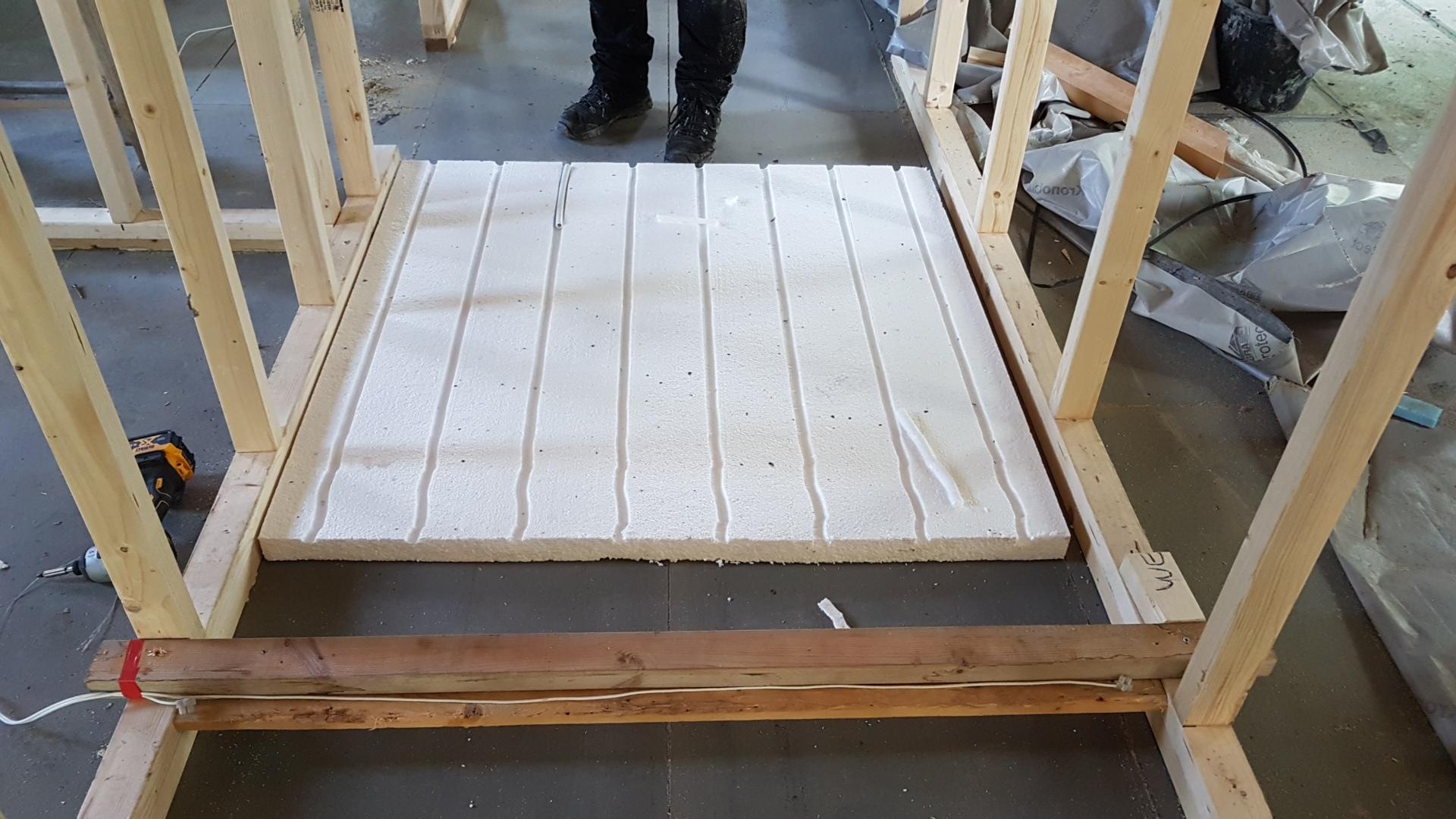
Wow that's a good guess, I was looking at Loxone! Any recommendations on the thermostats? I have seen the one @JSHarris used in his thread but the best I have seen are 0.1C increments - can we improve on that? PMSL! Maybe it's just as well that Kim is a lizard then! FWIW I designed the system in the original post based upon the DIY Heat Bank elsewhere on the tinterweb. And I am a self confessed cheapskate, bodger, curmudgeon. My rainwater system will use IBCs to save money, and I melted my own channels out of EPS70 to save about 500 quid on the upstairs insulation... The wood crossing between the walls has a series of loops of nichrome wire underneath, and the walls acted as a jig to guide the panels. Took about 5 minutes per 8' sheet of EPS, with 44 sheets to groove (and that's the feet of my eldest nephew who acted as a labourer for part of the project).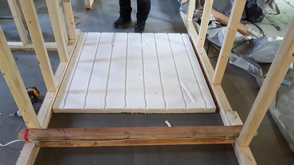
-
Heating system for an ICF house with UFH
Nelliekins replied to Nelliekins's topic in Other Heating Systems
I think in my mind I was going to address the differences in floor requirements / performance by just changing flow rates across the manifolds as a whole. If our EPC consultant is right, then we won't even need UFH upstairs, but it was put in "just in case". Kim wasn't convinced the house would be warm enough without, and she's a lizard (needs to bask because she is always cold). There is a fairly large stairwell, so a large volume of hot air is free to circulate between all 3 floors of the house. I am guessing that will help the upstairs temp as well? If the coil can deliver 6kW of heat energy, and our peak heat requirement from the UFH is 2.5kW to maintain 20C when it is -5C outside, that should be adequate for heating the UFH provided the flow rates are adequate (through the coil to the 3 manifold pumps). Failing that, we will have to get more cats... Even better, we can use the home automation system to control whether the immersion is used to put heat into the cylinder or the boiler or both, so some of the time it'll be free to heat... Provided I can get accurate temps into the automation system in the first place! ?