

Coping with a Thermal Flaw in the Design

Entry posted by TerryE
2960 views
(This post is a précis of a post and thread discussions that took place on the eBuild forum October last year and subsequent discussions with my builder.)
Many of the self-builders active on the forum will have used or be familiar with the Passive Foundation system marketed by MBC Timberframe. The essence of this is that the foundation is a raft slab that incorporates a ring-beam that sits inside an EPS former. This former both acts as shuttering for the concrete pour and as insulation between the slab and the underlying hardcore base. The slab is therefore wholly contained within the thermal insulation envelope of the house, typically giving an overall U value for the slab of around 0.1 W/mK. So far so good.
A variant of this is where the house has an external brick, blockwork or stone skin. In this case one approach is to pour a second outer ring-beam to carry the outer skin, and the MBC structural engineer (SE)
- Our skin is a rough-cut Cotswold-style limestone with an s.g. of around 2.5 (or 2.4 allowing for mortar); the walls are ~5m high, and the courses on average 125mm deep giving a linear loading of around 1.5 tonne/m rising to 1.8 on the 3 gables.
- The underlying ground is a very stiff impermeable (Oadby Member) clay, but
- We have some medium size tree quite near the foundations.
Here is a simplified diagram of this.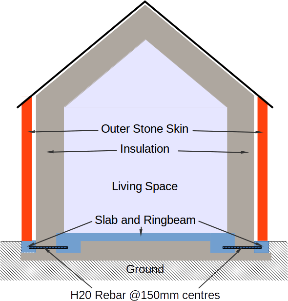
The SE specified bridging H20 rebars at 150mm centres to couple the inner and outer ring beams structurally, so that the load of the skin is carried across onto the main ring-beam and transmitted down through the ESP300 underneath the beams. If we assume that the load of the stone and house was carried only by the EPS300 sections of the slab, this gives an overall GBP of some 12 kPa and the 266 H20 rebars ensure that there will be minimal differential movement between the outer stone skin and the timber frame supporting everything else. This is comfortably within the allowable bearing pressure of 120 kPa recommended in the Geo-survey report. So this is a good structural design, but it unfortunately embeds a major thermal design flaw.
If you consider the thermal cross section of the total rebar, it is pretty much the same (from a thermal perspective) as replacing the rebar and the EPS between the two beams by solid concrete. To be honest I along with everyone else missed this thermal design flaw when I was given a copy of the slab design to review. The penny only dropped for me when I saw the rebars in place, and the concrete was just about to be poured. The inner slab and ring-beam is within the insulation envelope of the house, but the outer ring-beam is at ground level and directly carries the stone skin.
- In the base design this would be fully exposed to the elements and could often drop to ~0°C or below in winter.
- The 266 × 2cm diameter mild steel rebars have a total cross-section of 0.084m, and this couples a slab at roughly 21°C with a ring-beam at roughly 0°C across a 20cm gap.
- This is a pretty perfect thermal bridge as steel has a thermal conductivity of roughly 40 W/mK -- this means that we will lose heat at roughly 21×40×0.084/0.2 W = 350W or 8.5 kWh / day in colder winter months through these bars.
- This is over 3 times the design figure of 2.6 kWh for the entire slab.
Here is a small extract from the slab engineer's design. I've coloured the different components and removed a lot of the structural detail which isn't relevant to this discussion, so we can focus on the issue here.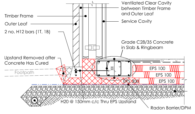
We were too late to change the design fundamentally, but if left uncorrected, this flaw would result in the slab being the single largest source of heat loss (more than the walls, the roof, or the windows and doors for example). So after discussion with MBC, Hilliard their SE, and members on the eBuild forum, what we decided to do was:
- We retained the outer EPS formwork that wrapped the outer ring-beam.
- This still left a thermal bridge between the top of the outer ring-beam and the stone skin it was carrying. Hilliard confirmed that a course of Perinsul Foamglas would be capable of supporting the design load of the skin and largely close the thermal bridge.
- However, we would then have an exposed ESP front and FoamGlass course edge which is cosmetically crap and vulnerable to rodent damage.
- So after discussing options with our builder we decided to cover the entire exposed EPS / FoamGlass surface with some courses in engineering brick.
- And when the skin was complete we would then put a perimeter path 60cm wide and 10cm (min) deep around the house on the crushed stone bed.
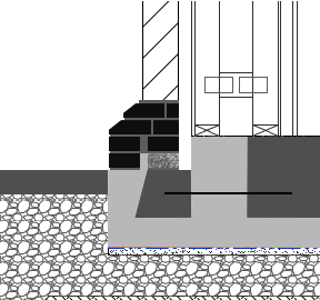
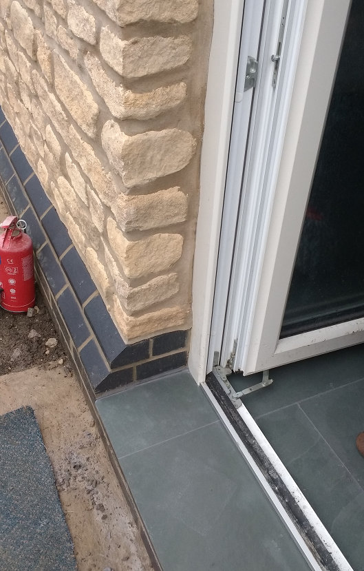
Here is a simplified schematic that I drew up for my builder of the approach that we finally agreed on. What he did was to use two external courses of engineering bricks as an plynth in front of and on top of the FoamGlass, followed by two header courses to step back the wall line. This engineering brick wrapper is primarily cosmetic and a weather protection as the load is actually carried down vertically through the FoamGlass onto the ring-bean, I've also included a photo of the plinth at one of the rear French windows where you can see how it looks in practice.
There is still going to be a little bridging on the diagonal between the ring-beam and the outer engineering brick layer, but my rough estimate is that this will be more like 50W rather than the 350W discussed above. An extra 1.5kWh/day, I can live with.
-
 3
3
0 Comments
Recommended Comments
There are no comments to display.
Create an account or sign in to comment
You need to be a member in order to leave a comment
Create an account
Sign up for a new account in our community. It's easy!
Register a new accountSign in
Already have an account? Sign in here.
Sign In Now