JackOfNoTrades
-
Posts
40 -
Joined
-
Last visited
Everything posted by JackOfNoTrades
-
Sorry, this should have read that the middle of the chimney is the middle of the party line.
-
Nope - that chimney is right in the middle of the building and evenly straddles the property line.
-
Thanks everyone. This really helped. I wasn't missing anything and my confusion at their approach was justified. Thanks all for helping confirm I'm not going mad.
-
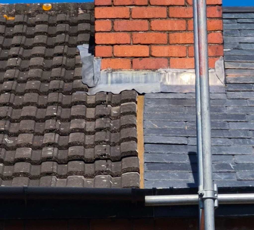
Hi roofing afficiandos, I've just had the roof replaced (pretty much one of the only things I haven't done myself as my roofing skills max out at flatroof EPDM on the outbuildings). The scaffolding came down a few hours ago and this is what the bonding gutter looks like. Our neighbour (who is very laid back and never once complained about anything in the years we have been neighbours) pointed this out before I saw it and asked me when the roofers can come back and fix it. The roofer is standing by this job by saying "There is a bonding gutter Between the roofs there as to be a gap". Can I check if I'm wrong in thinking this is an unusually wide, messy and offcentre bonding gutter? Life is busy and I need to know which battles to choose, having already had to fight a few. Thanks for your thoughts everyone! It's appreciated.

-
Yeah, I understand what they've done from the diagram . It's the *why* they've done it that way that's getting me. And the fact that there's seemingly no ventilation but they claim there is.
-
Sorry. That's confusing of me. One of them is on the inside side of the wall, but the reason I was adding that bit was to make it clear it's a continuous sheet and not between the timbers.
-
Just thought... Here is their diagram in case it helps
-
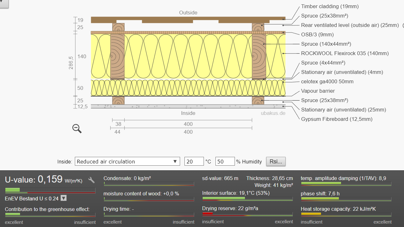
Hi all Can I pick your brains? I was looking at alternative cladding options for a timber frame conservatory wall and found a diagram of Dunster House's Addroom wall. It makes no sense to me ... so I'm trying to make it make sense just so I can learn something from the process. The wall is ... - 10mm wood polymer composite external cladding - 25mm PIR - continuous outside of frame - 75mm timber frame - 25mm PIR - continuous on inside side of frame - 10mm fermacell fibreboard interior wall They also say "The walls have a 70mm cavity to increase airflow and ventilation" I know this is a conservatory alternative not a traditional building, but it seems to fly in the face of what I know about timber build. To help me get my head around it, could anyone throw in their two cents on the following? - Would there not be a condensation point in the middle of all this? - How is it working without an air gap behind the cladding? - What do they mean by "70mm airgap for ventilation", when it seems from the diagram that the only airgap is in the timber frame itself ... and that's presumably sealed by the PIR? Thanks for your ideas everyone. Jack
-
Timber frame allowing for close proximity to neighbours….
JackOfNoTrades replied to G and J's topic in Timber Frame
Sheets directly on the osb. But then battens and fibre cement cladding over. -
Timber frame allowing for close proximity to neighbours….
JackOfNoTrades replied to G and J's topic in Timber Frame
This is precisely what I'm doing. The wall facing the boundary has fibre cement board cladding, and I'm having treated larch elsewhere. Double check your SE is happy with this too. I wanted to replace my external OSB3 with cement board sheathing, but have been told I need to add it in addition to the OSB as they couldn't find the details on the cement board to do accurate racking calcs. -
Piled foundations and private drain question
JackOfNoTrades replied to JackOfNoTrades's topic in Foundations
Thanks for the reply Conor, I guess what I'm struggling with is ... isn't the reinforced ground beam a huge lintel in this context? Given that the lintel above the granular infill will be in the same direction as the ground beam, does it actually protect the drain?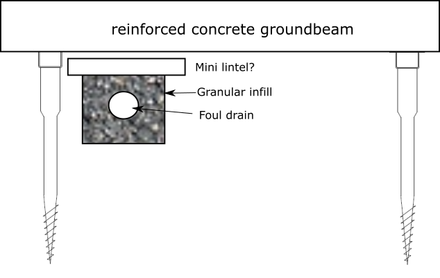
-
Piled foundations and private drain question
JackOfNoTrades replied to JackOfNoTrades's topic in Foundations
Afraid that's not possible due to where it leaves the property. That would be the dream though 🙂 -
Hi all For a number of reasons, I've had to opt for foundations of a reinforced ground beam supported by screw piles. There is a private foul drain running underneath the new extension and as it stands the drain will go under the ring beam, between two of the screw piles. I'm obviously planning on surrounding the pipes with pea shingle as it's going under the building, but I'm trying to work out if I need to provide any other protection above the plastic drain. If this was a traditional trench foundation I'd obviously have a lintel, but I can't find anything clear on the regs with ground beam and screw piles. The pipe will end up being around 200mm - 300mm from the bottom of the reinforced ring beam. But the screw piles will go a few metres below the drain. As far as I can tell it, the things I can do to support the pipe are: 1. Add flexible joints to the pipe either side of the ring beam. 2. Add another concrete slab/lintel above the pea shingle. (As in Approved Doc H for shallow laid pipes - although there might not be enough room for this between the screw piles as Doc H states minimum bearing of 300mm each side, plus 100 granular.) 3. Nothing - the ring beam acts as a lintel sat on top of screw piles that go below the depth of the drain. Any thoughts on the above would be really appreciated. Thanks all!
-
Hi all, I am investigating mini piling and ground beam options as I'm having a few issues with my soil, hedges and trees, neighbour's extension location and the miniscule depth of my existing brick footings. I came across Shire's Quickbase foundations and wondered if anyone has seen them in action? It seems to be a concrete free pile and beam offering. Helical screws, then a plastic prefab beam which gets filled with a grout onsite to make it rigid and a proprietary floor slab on top. All installed in a day. They seem to be mostly used for conservatories, but also some single story extensions. As I'm doing a timber build and timber clad extension they might work. Has anyone seen them in the wild? Any thoughts on the longevity of something like this? Thanks in advance for any thoughts
-
Builder's upstand vs proprietary
JackOfNoTrades replied to JackOfNoTrades's topic in Skylights & Roof Windows
Actually just seen that they have a video of this application on their youtube channel. Seems remarkably quick. Did you have any pushback from your BCO about the Euroclass E fire rating on your roof? Or is it so small a percentage of the build that they are OK? Fair point. I think I have a few other areas in the build that might need the BCO's good will ... so I want to demonstrate I'm comfortably within their expectations everywhere I can. -
Builder's upstand vs proprietary
JackOfNoTrades replied to JackOfNoTrades's topic in Skylights & Roof Windows
Cheers for the suggestion. I'll take a look. Don't suppose you have any photos? No worries if not. I'm leaning towards non proprietary. Especially as I can build it ahead of time so during the build I can just install it with the same speed as proprietary. -
Hi all. I'm just choosing my rooflight and wondered what the consensus was on proprietary upstands vs builders upstands. As far as I can work out Proprietary Pros: - quick to install and get watertight - can easily demonstrate full u value to BCO Cons: -if you need to replace window in future you better hope they still sell that model - limited size options Builders upstand Pros: - custom size - future proof... If glass breaks the are many places you can get custom replacements from Cons: - Demonstrating overall u value harder - takes longer to get watertight roof Does anyone have any experience they could share on this ? Cheers.
-
Feedback on timber extension structure
JackOfNoTrades replied to JackOfNoTrades's topic in Timber Frame
Good point. And actually I don't really need that extra joist by the side of the wall, so I can extend the flying rafters to the next joist. It's only a 68mm extra overhand on that side, but it also removes the (unnecessary) weight of the extra joist on that wall..png.7f14d96bfe0e149686d840235101f1fc.png)
-
Feedback on timber extension structure
JackOfNoTrades replied to JackOfNoTrades's topic in Timber Frame
Fair point. I am now considering including 150mm insulation (costs and extra £130 for this build to beef it up) particularly because I need to lay some telescopic vents in that space to ventilate the suspended timber floor in that part of the old house. Doing 400 centres on this one. To be honest, I do prefer including noggins, even though I know at 400 the OSB should do the job, but it just doesn't feel right. I did noggins on my last build but here I am trying to reduce the amount of timber bridging because of the required size of jack studs elsewhere. I'm using VL on the boundary facing side (no access so once that wall's up I want it to be up and maintenance free until after I'm dead. A slither of it will be visible by the neighbour so I'll want it to look nice for them too). But then I'm using open slat Siberian Larch cladding on the rest of the build. I just like wood. Still working on this. The TRADA publication on it says that shot fired is most common method with masonry nails going at least 25mm into the blockwork - not comfortable with shooting nails into blockwork - and regardless I have the thermoblock in the way. Other options: Straps - pros: not going anywhere on a windy day. No penetration of DPC. Can extend below the thermoblock easily. Cons: at risk of corrosion externally? U-shape or L-shape anchor - Pros: can bolt deep down through marmox and into the blockwork. No penetration DPC. Cons: Would need long expanding bolts to get it through marmox and into the blockwork. The thickness of the anchor on top of thermoblock stops the surface from being 100% level for the sole plate. [EDIT - but could obviously use mortar to level it] Just bolt it through - Pros: simple, all self contained within wall. Cons: Need to squirt something down to seal the DPC. Bolts need to be long. Think I'm leaning towards anchors at the moment. Thanks for all your thoughts and comments. I really appreciate it loads. -
Feedback on timber extension structure
JackOfNoTrades replied to JackOfNoTrades's topic in Timber Frame
Well spotted that I didn't have that in the u calc I shared. I'm using open joint cladding so I'll need a UV resistant breather membrane. So I'm looking at TRASPIR EVO UV. Used tyvek on my other timber build just because it was the standard and was my first build. -
Feedback on timber extension structure
JackOfNoTrades replied to JackOfNoTrades's topic in Timber Frame
Hi Redbeard. Not going for underfloor heating here. Family member had a tradesman come and drill straight through underfloor heating after promising he wouldn't. I've stayed away from it ever since. Irrational I know ... but that's me. Using Celotex 100mm I'm getting 0.18 for the floor. (the required u-value for the extension) Using the same thickness of kooltherm k103 I get a pretty decent 0.15 ... although at a whopping 3 times the cost. EDIT - and upgrading to 150mm of Celotex would give 0.13 While I'm all for improving u values where necessary - particularly in a new build - I'm a little conflicted about spending much extra money on incremental improvements .... when the extension is attached to a building with solid brick walls with a u-value of 2.0. -
Feedback on timber extension structure
JackOfNoTrades replied to JackOfNoTrades's topic in Timber Frame
If I raise the height of the front wall by reducing the depth of the fully supported joist, I can have an uninterrupted top plate that spans the distance (highlighted in green). Still not perfect but potentially much more structurally sound. In this render I've hidden the front joist so you can see everything. And a side view to show the full depth joist next to the wall, and the shorter joist resting on top of the (higher) front wall. A little unconventional maybe, but could this have solved my problem of the lintel being too high?.png.04734c919b8f34a4cc7bb90c3529d724.png)
.png.500c6c0be6a436fbf0f30937cc858b33.png)
-
Feedback on timber extension structure
JackOfNoTrades replied to JackOfNoTrades's topic in Timber Frame
ubakus. It's pretty decent. -
Feedback on timber extension structure
JackOfNoTrades replied to JackOfNoTrades's topic in Timber Frame
Not yet. I'm pre submission (just about to send it all off in next few weeks). It should be fine though. The required u value for an extension wall is 0.18 This build up gives me 0.159 if I've done my sums correctly.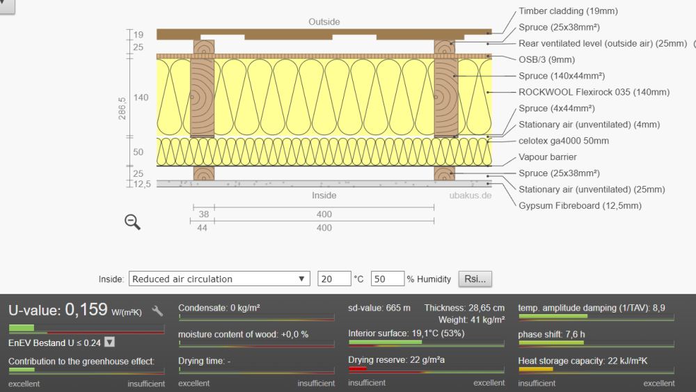
-
Feedback on timber extension structure
JackOfNoTrades replied to JackOfNoTrades's topic in Timber Frame
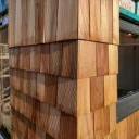
This is what I'm using on the wall that faces the neighbour's extension. There's no access there so I need something that will need no maintenance and is nicely fire resistant.