lineweight
-
Posts
91 -
Joined
-
Last visited
Everything posted by lineweight
-
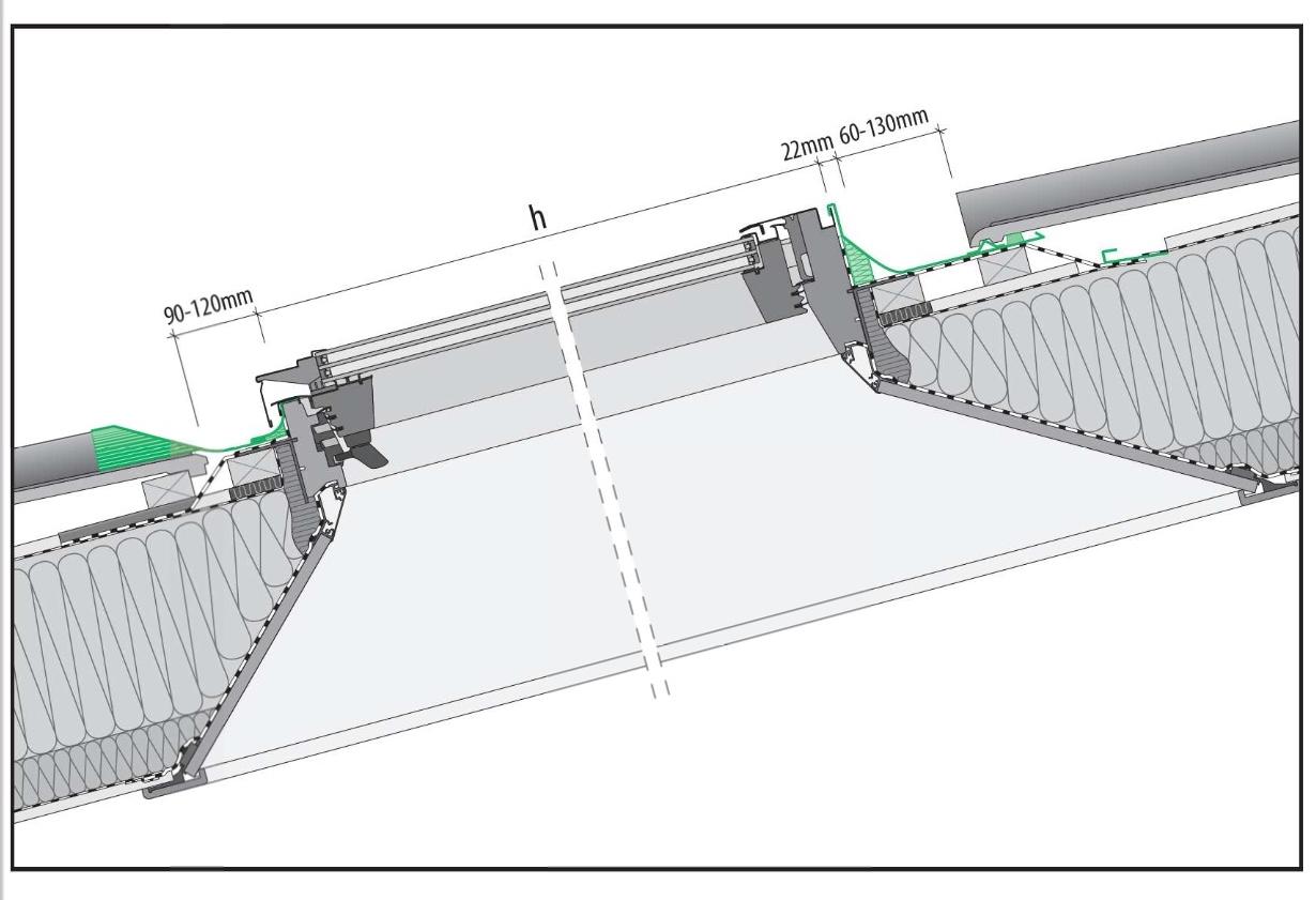
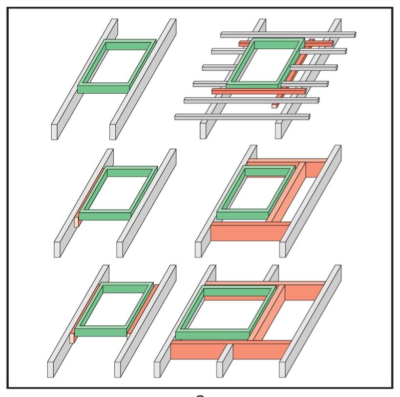
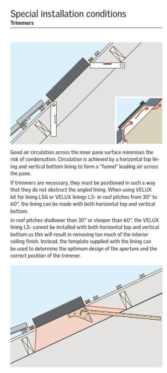
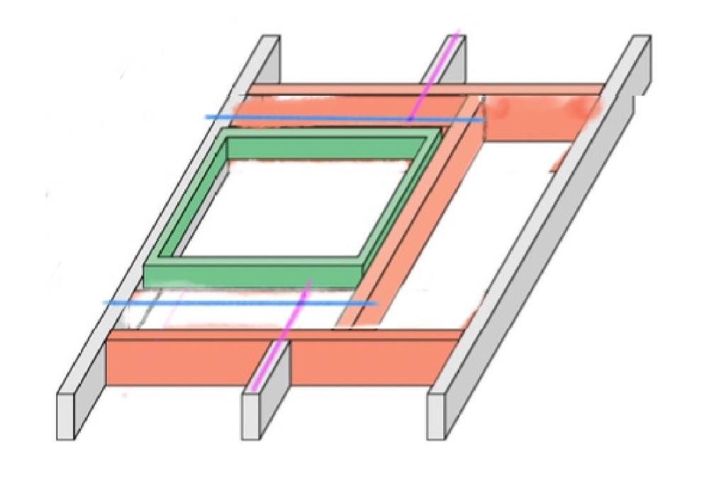
Maybe I am missing something obvious but the information that eg. Velux and Fakro supply remains rather silent on exactly how splayed reveals at the top & bottom of rooflights are supposed to be formed. They both show & recommend these splays in diagrammatic form: Ok, so to achieve these splays, of course you have to set any trimmers back from the opening, as indicated in the Velux diagram. There are some more detailed drawings that include these splays - for example this from Fakro: Here, trimmers simply aren't indicated. My basic question is: what is supporting the roof tiles/slates in those portions that project beyond the set-back trimmers? If the roof window width is less than the rafter spacing, then there's no big issue, because the tile battens simply span between the rafters like anywhere else on the roof. But what if the window is wider than the rafter spacing? Then you have the scenario at bottom right here: This drawing kind of fudges the placing of the top & bottom trimmers, relative to the roof window frame. But if we assume they are placed to allow splayed reveals, as indicated in my butchered diagram here: Then it seems we are asking for either or both of: (a) tile battens (indicated in blue) to span more than a normal rafter spacing. This can be up to 1.4m for the largest windows, so more than double a 600mm rafter spacing. (b) if counter-battens are involved (indicated in pink), then they can project beyond the cut-off point of the rafters, but we are essentially asking them to cantilever, and with many geometries this is easily going to be 200-300mm so several tile gauges. Am I worrying about a problem that doesn't exist in practice (battens/counterbattens will cope with this fine, even with big openings)? Or is it that Velux/Fakro don't show what is supposed to happen because actually it creates a slightly dodgy detail that they don't want to explicitly recommend? Is it that actually some kind of reinforcing something has to be added underneath the tile batten, which creates a messy situation as far as insulation/membranes are concerned and they don't want to draw/recommend this? If it's the case that the splayed reveals are only really possible with narrower windows, why don't they just say this?


-
You mean internal partitions I guess? You can carry on building up external walls and loadbearing internal walls, can't you, before the screed goes in?
-
I'm not a particular expert on this but I think you would have to allow for the possibility that it could shrink again. I think the process can occur to some extent on a seasonal cycle as the amount of water in the ground increases and decreases. With a suspended slab are you still obliged to provide ventilation to the cavity underneath?
-
Thanks, I had not come across this option before. I can see that it potentially lets you use the beams and the screed layer as thermal mass as they can effectively be "warm" inside the insulation envelope. Do you have any experience of how it ends up comparing cost-wise with a conventional b&b buildup?
-
Presumably it depends whether the void formers are the type that are designed to disintegrate? If they are to deal with ground heave then presumably they are - in which case wouldn't you end up with an airspace of some kind under the slab?
-
I suppose I am a bit wary of timber here because we have to have an internal floor level not much higher than the surrounding ground level, so to avoid those timbers getting wet would rely very much on various damp proof courses and membranes being done properly and carefully, and then ventilation not getting blocked in the future, and so on. I'd agree timber suspended is worth considering where you're well above ground level.
-
What makes it more costly - the bits you buy from Jetfloor?
-
That's right yes, in this case.
-
usually there is supposed to be some kind of reinforcement mesh in the screed, is that right?
-
I'm assuming you are using their "Litecast GT" or "Litecast XT" systems? For you, what swung the decision to use something like this, rather than conventional beam & block?
-
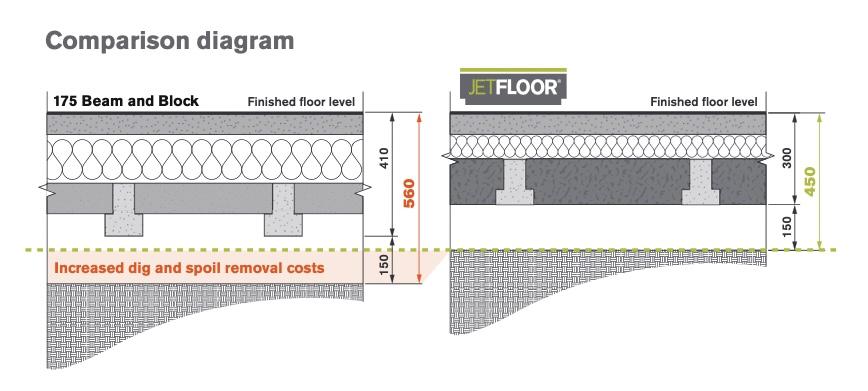
There are various beam & block systems which use polystyrene blocks instead of concrete blocks inbetween the beams. Then there's another layer of polystyrene and then a "structural topping". Systems include Jetfloor or Warmfloor Pro. Essentially they reduce the overall floor buildup thickness by moving some of the insulation layer thickness between the beams, as well as potentially using the "structural topping" to reduce the beam size necessary. If I have understood correctly. This diagram is from Jetfloor literature: Where they argue the Jetfloor system is more cost effective than a conventional B&B buildup. They compare a Jetfloor system with 150mm beams vs conventional using 175mm beams. They both achieve the same U-value. It implies that you might save 100mm of ground excavation. However, if you only need 150mm beams in the first place, that's down to 75mm. I'm wondering if anyone has any experience where using an insulated-block type system really did save any costs. Especially on small jobs, because usually it's best to stick with something that most builders are familiar with.
-
Do you recall roughly how much it cost? It looks like you have to order directly from Armatherm, is that right? In other words there's not really a standard product that can be bought off the shelf.
-
Yes, I see, hadn't noticed that's how it works. I had already ruled out these Shoeck blocks for the same reason. https://www.schoeck.com/en-gb/type-m
-
Thanks @Mr Punter and @Tom, that makes sense. I actually was just looking at Armatherm and Farrat but they don't illustrate their products used in quite that way either; they all seem to be intended for situations where the material is between elements bolted together.
-
There are a few products such as Foamglas Perinsul or Marmox Thermoblock which are intended to be used in situations such as the base of walls, where there needs to be a loadbearing thermal break. In refurb projects I commonly come up against situations where a nominally "warm" (ie, it's inside the insulation layer) steel member needs to come into contact with cold masonry. For example, where the beam needs to sit on a padstone in an existing brick wall, which can't be insulated externally. (Same happens with a party wall with a cold loft space on the other side) Or, when propping the tops of chimney stacks when the chimney breasts have been removed below. In these situations the thermal bridging could be reduced by using a layer of something like foamglass inbetween the steel and the masonry. Such a use doesn't seem to be described in the literature for these products but I am wondering if it's something that anyone has seen done successfully. Or perhaps there is some other product for the job that I'm not aware of.
-
Is insulation *outside* studs considered unconventional?
lineweight replied to lineweight's topic in Timber Frame
I just asked about this on a TRADA timber frame webinar. Asked why insulation external to the timber structure seems relatively conventional if you are talking about a roof, but not a wall. The answer was basically to do with ease of construction, how you fit the external layer and then provide support for whatever cladding type you are using. However, they also said, that things might need to start changing, now that building regs are more concerned about thermal bridging (and achieving better U values in general). So, we might start to see details with external insulation become a bit more comonplace. -
No, not as far as I can tell.
-
In the pavement? The only other one I can see is the neighbours'. As far as I know, the stop tap was in this hole before the meter got put in.
-
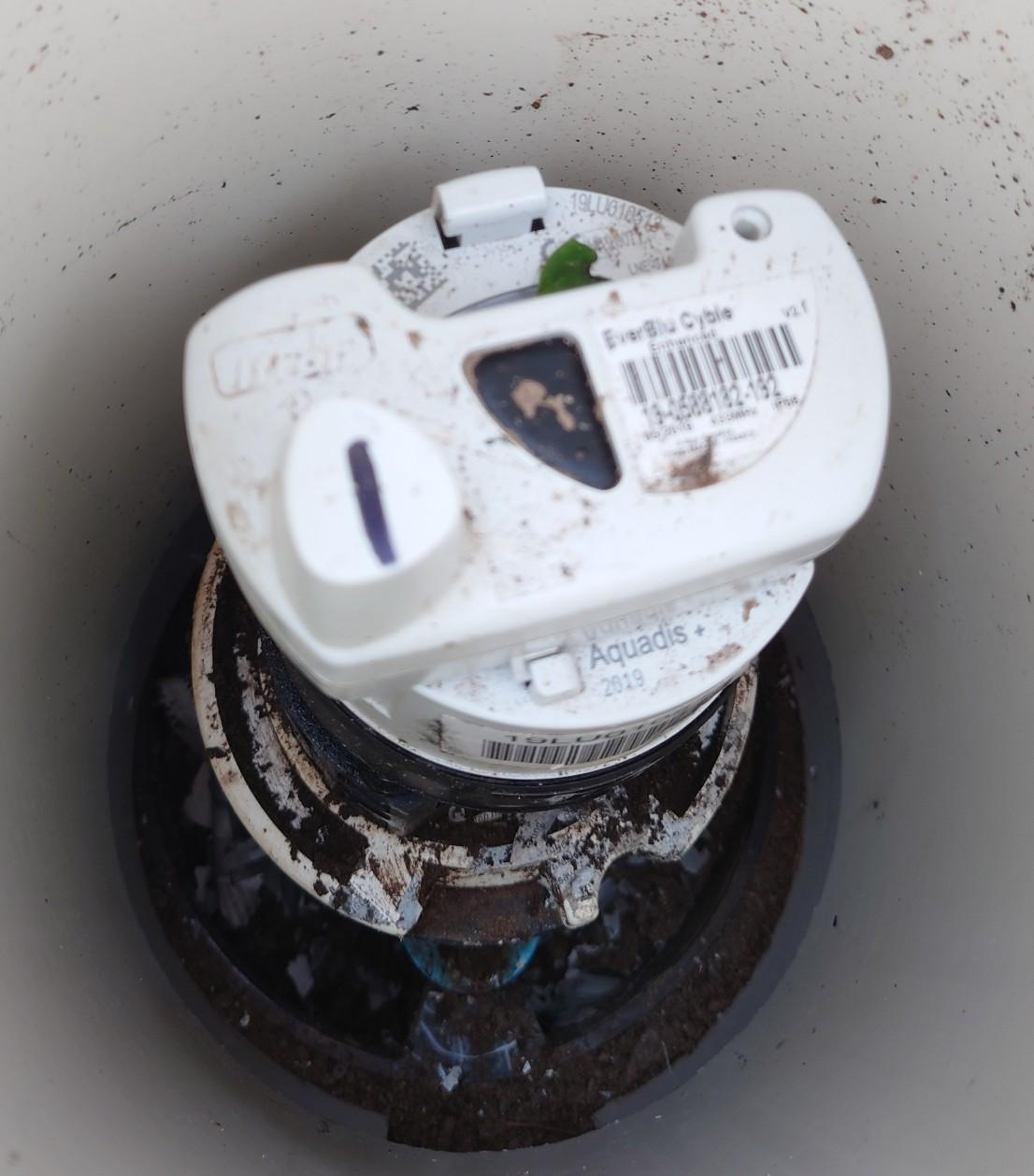
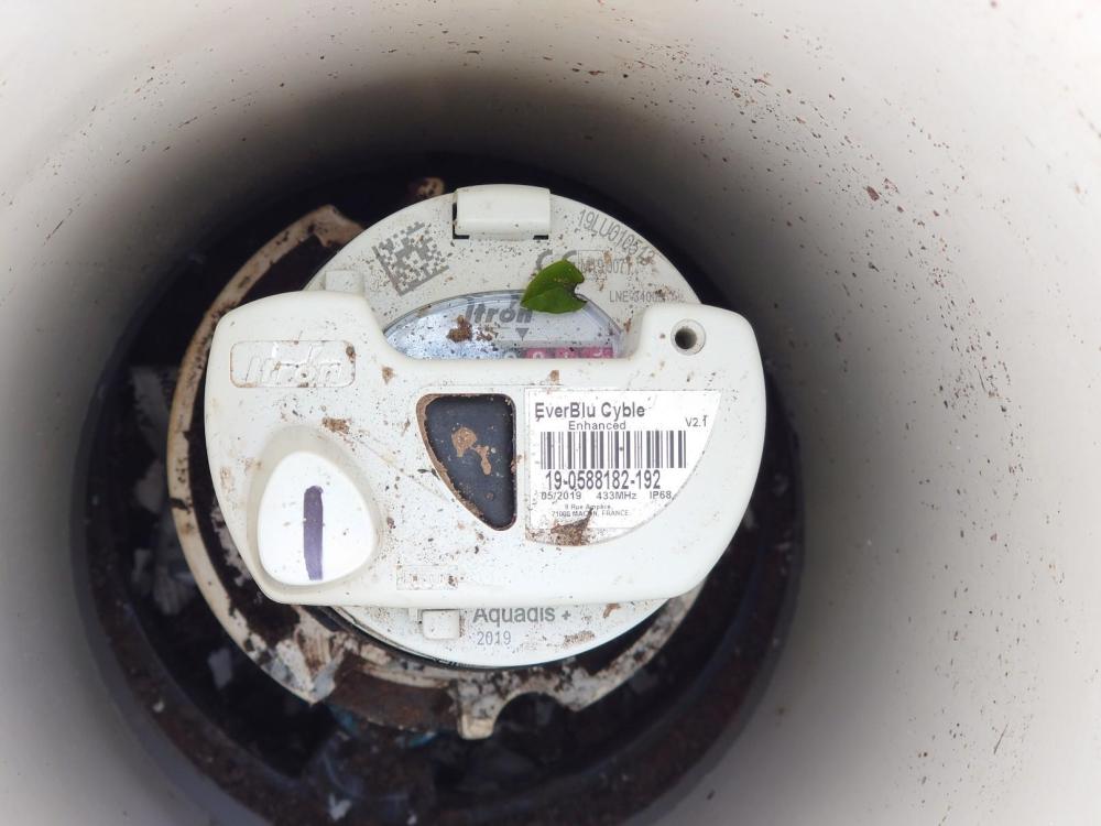
I'm trying to turn the water off in a relative's house - the internal stop cock is seized so went to look in the manhole in the street. However there's a water meter in there - quite recently installed I think - but no obvious stop cock. Is anyone familiar with this type? Is there something built into the meter that allows the water to be turned off?

-
Yes, this is exactly what happens.
-
It's been installed for a little while - is technically under warranty but from a company who have now shut up shop in the UK and don't seem interested in honouring it. So, I doubt I'm going to have any luck there. The question is about what the options are for fixing it, rather than who pays for it. Will have a look at the GGF website, thanks.
-
I have a problem with a triple glazed sealed unit. The inner and outer panes are bowed inwards, towards the middle pane. They are badly bowed enough that they actually touch the middle pane at the centre of the window, especially during the winter when it's colder. From what I've worked out so far, this is most likely a manufacturing defect, and is caused by the pressure inside the unit being too low. Although, it could perhaps also be the case that the panes are simply not flat, and the distortion is intrinsic rather than being caused by a pressure difference. Of course, to fix this, I could simply replace that unit. But aside from the expense of a new unit, because of the particular window system, I know it would not be straightforward job and might require a partial dismantling of the frame. My question is, is there any way of trying to fix this in situ? I find some references to the possibility that there is a specialist repair which involves drilling a small hole through the frame and edge spacers, or maybe even through the glass, but I can't find any company that explicitly offers this. If anyone has any info or experience with this, it would be gratefully received.
-
Insulation in a 1960s flat roof - any guesses?
lineweight replied to lineweight's topic in Flat Roofs
yes... had wondered about that. -
I'm trying to make an estimate of the U-value of an existing flat roof, constructed in 1963. On the original architects' drawings, it's noted as "Briggs Patent Roofing" which I think just means a layered felt system. This is laid onto "1/2 inch insulating board" with no further info given. Does anyone have any guess as to what this 25mm(!) insulating board is most likely to have been, given the construction date? Some kind of celulose/wood fibre board?
-
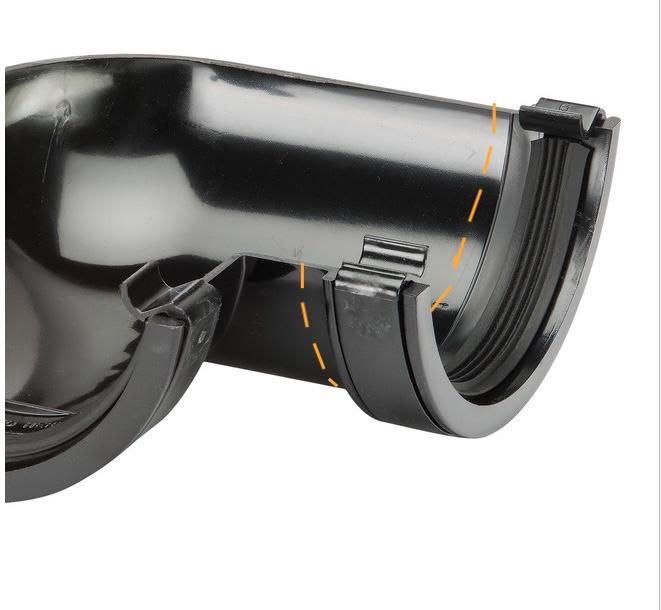
Proper way to do a double 90deg gutter offset
lineweight replied to lineweight's topic in Rainwater, Guttering & SuDS
Thanks. Do you mean cut on this sort of line? Doesn't this mean that you are trying to fit one bit inside the other when they are actually the same diameter - or is correcting that what you mean when you suggest deforming it by heat?