NandM
-
Posts
140 -
Joined
-
Last visited
NandM's Achievements
Regular Member (4/5)
4
Reputation
-
Restraining column against existing wall
NandM replied to NandM's topic in RSJs, Lintels & Steelwork
Finally got a response today - it's fine not to restrain into the existing wall, but must be retrained into the new walls. -
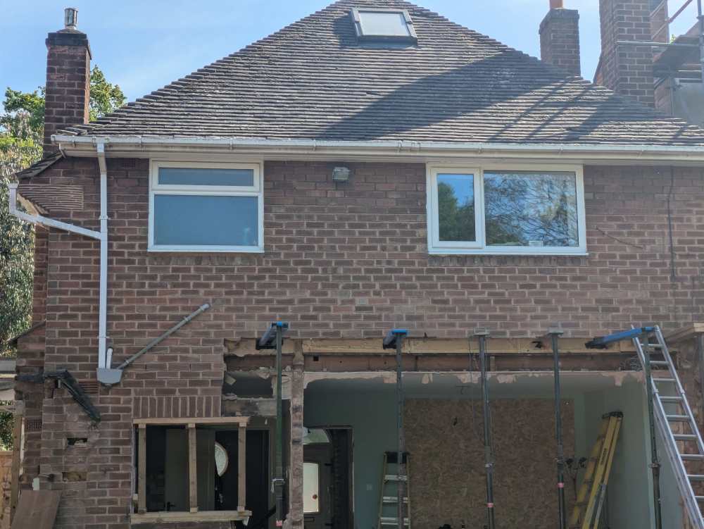
I was hoping to leave most of the demolition work until the brickies were ready to build the gable walls, and minimise the risk of rain damage. But now I'm thinking the old structure is getting in the way too much. I need to get services in the ground and start levelling the oversite etc. In the picture it's the whole left hand side that will need to go and also around the side about the same width. I was thinking about removing the roof tiles to minimise pressure on the walls and use something like dpm as a temp covering. Then to add series of hefty cross beams, before removing that corner of the roof and working down. The three chimneys will also need to be removed. Would removing the tiles from the roof be sufficient to reduce the spreading force of the roof into the walls?
-
Restraining column against existing wall
NandM replied to NandM's topic in RSJs, Lintels & Steelwork
It's the old adage of you get what you pay for! ....and don't get me started on the comms 😂 -
Restraining column against existing wall
NandM replied to NandM's topic in RSJs, Lintels & Steelwork
I'm waiting on a response, but they've not been great so far and seem to lean towards difficult solutions rather than practical. -
My SE has specified the use of Ancon SPB or similar farme cramps to restrain the new steel column with the existing wall. It fairly clear how this would work with the new block wall, but I can't see these being useful with the existing, unless I need to scrape out and then re-motar? What other alternatives are there? A simple option I can think of is the use of masonry framing screws, or for something more robust resin some bolts through into the wall.
-
I've had several quotes in Brum all around 120-140 mark.
-
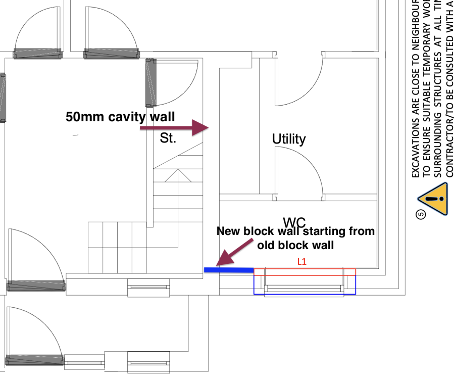
As part of our proposed extension work, a current external cavity wall will become an internal wall. The current brick wall will have a 100mm slit to act as a thermal break, but I will still have a approx 4m length of cavity that is still "connected" to the outside. Do you see this causing any issues with heat loss? I can wet plaster both sides to help with airtightness - but I really don't want to add insulation to the walls on both sides (although I could fill with eps beads). The one idea I have in mind is to start the new block work from the old block work by having an approx. 250mm opening down the entire side of the wall and joining the two. This will result in a separation between the" internal" cavity and the external one. There are two challenges I see here: 1) with the 250mm opening, could it be done from bottom up without the need for any lintels. Google tells me this should be OK. Otherwise, we could do it top down. 2) the new block that will connect to the old would have to use whatever the current foundation depth is - at least for 150mm of the block. Would this be a problem?
-
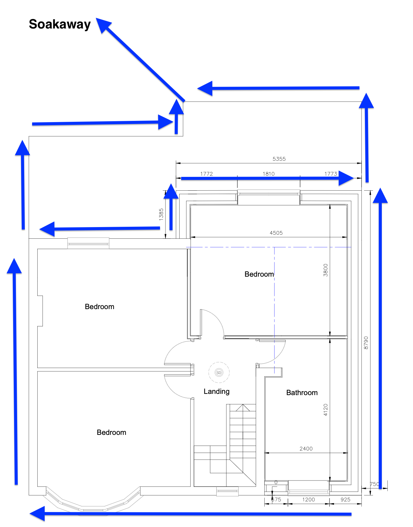
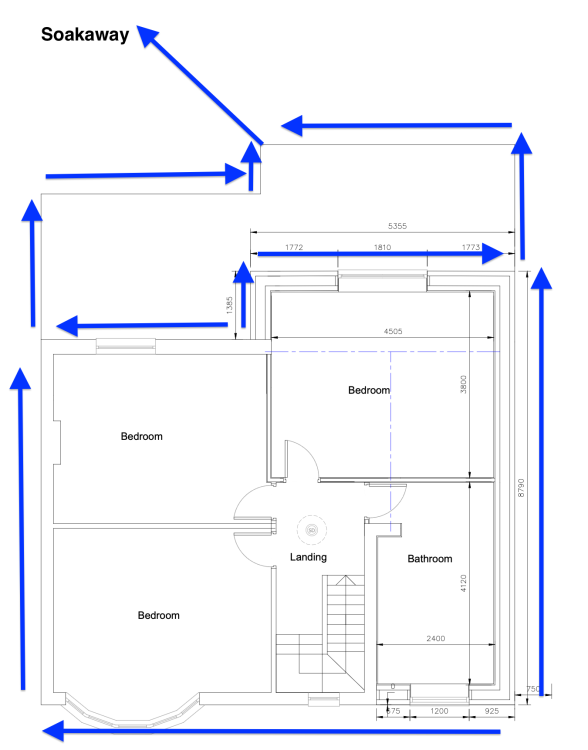
I'm finally about to start the groundwork (yay!) and am thinking about the best way to get the rainwater to the soak away. I'm hoping my simple design by routing all the pipes to one outlet would work? In effect the pitched and dormer roof to route down to the flat roof pipes on ground floor and from there to one gulley and then to the soak away at a distance of 5m, and under 4m of patio.
-
Why do the timbers need to sit proud and would 10mm be enough?
-
And are they left in place as the concrete is poured? (I'm hoping to (finally) start my extension in coming months)
-
What are those "mars bars"?
-
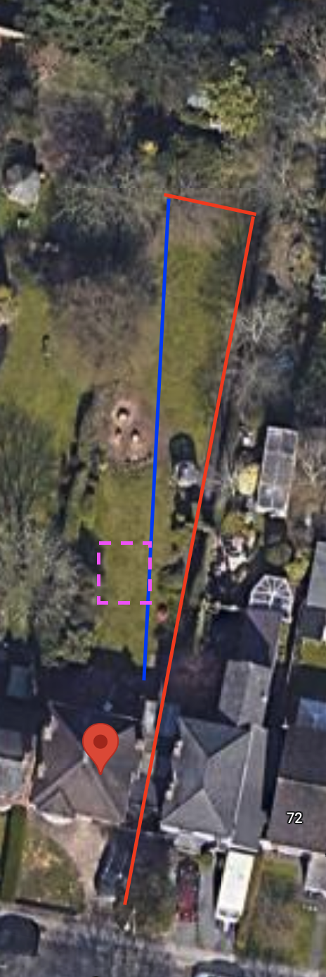
I think just laziness on my part! I'll bury it and keep the pipe overground for now as per the blue line.
-
I wasn't planning to bury the mdpe underground to start as I have a run of around 65m to the front garden. Current temporary plan is to follow the hedge up the garden and then through the back of the garage and into the main inspection chamber at the front of the house. Once we have the new sewers put in as part of the house extension, I could route underground like the blue line and have the mdpe terminate into a 110mm pipe underground.....and bury the station. But I need everything working before the demolition starts.

-
Above ground sewage stations seem to come at a premium, so I'm wondering if I can use a below ground one above, or even partially underground to save on the digging. The bathroom I'm adding to the garden room is currently about 30cm above ground level - I could probably raise this another 10-15cm internally. I've seen some of the underground stations that have the inlet very close to the bottom - so if I have the drop, then what's stopping me from using one of these above ground? e.g. clickity and click
-
(Hopefully) a simple drainage design - but help always needed!
NandM replied to NandM's topic in Waste & Sewerage
I had my first trader (bricky) over yesterday and he mentioned there may be difficulty in getting an inspection chamber in place because of the available space. Between the outside wall and the neighbours wall will be our alley way of approx 850mm width. I've had a look through Document H and couldn't find anything specifically about IC and how close they can be to a wall. I was also looking at Diagram 8 and for clarity, as the distance of the new drainage will be less than 1m from the footing, how much lower does the new drainage than the footing? This also seems contradict some posting I've seen that say the footing should at least go to the lowest part of the drain pipe.