jimseng
-
Posts
170 -
Joined
-
Last visited
Everything posted by jimseng
-
I wondered about running some fibre in too, maybe just a couple of places like office to plant room but it seems a bit more complicated. I don't mean actually terminating the ends, just having it within the fabric of the building and left as a coil behind a blank plate. I doubt I would ever need it but in the future someone might appreciate it. I hope I don't regret not doing it.
-
Thanks. I had forgotten about the cca aspect. That's why I asked, I thought it was too cheap on ebay.
-
This has to be a simple one but cat6 UTP for 1/10gb ethernet and RS485. On ebay a box of 305m white is £43.85. Is this poor quality? I'm just running Ethernet around my house build, nothing specific. I know cat6 isn't really RS485 impedance but at low data rates I think I'll get away with it. trying to save money on everything but I don't want to buy cheap from ebay if it is fake/rubbish. Any thoughts?
-
Batteries in plant room and 120 minute fire rated walls
jimseng replied to jimseng's topic in Energy Storage
At the risk of repeating myself, that video is of non LiFePo4 batteries! It looks scary but that sort of thermal runaway is specifically what LiFePo4 batteries were designed to avoid. I guess that's why they are starting to put them in EVs now. There are many but this is quite a fun video: -
Batteries in plant room and 120 minute fire rated walls
jimseng replied to jimseng's topic in Energy Storage
The key words there are "anecdotal" and "loose connections". Putting 32kw of energy in a small box carries a risk that if you allow it to escape quickly and uncontrolled it is probably going to say "boom". That is the same for Lead acid batteries, which also give off very nasty gas when they go wrong. -
Batteries in plant room and 120 minute fire rated walls
jimseng replied to jimseng's topic in Energy Storage
The Fogstar batteries I have just bought have this built in. -
Batteries in plant room and 120 minute fire rated walls
jimseng replied to jimseng's topic in Energy Storage
The interesting thing about much of the discussions about fires and Lithium batteries is that they never seem to refer to LiFePo4 batteries. There is the same thing going on in the marine industry where people panic at the word "Lithium" but I have yet to see an actual report of a fire being caused by a LiFePo4 installation. The famous one recently was the Northampton canal boat explosion which has been linked to the battery installation as it was an electric boat. There are pages and pages of discussions, arguments, yelling, but I can't find an actual qualified report of what caused the boat to explode, only a comment from the fire brigade who attended on the day. The same with the boat that caught fire in Torquay a couple of years ago. It had just had a battery system upgrade "therefore" it was a Lithium battery fire. My understanding about LiFePo4 vs other chemistry is that is specifically does not produce its own oxygen and other Lithium batteries do. Cheap e-bikes etc seem to be what cause terrible house fires. Maybe I'm wrong and I keep looking for credible evidence to the contrary as I have LiFePo4 on my boat and I like to be informed. Anyway. I am concluding that I should be proactive about what goes on the walls of the plant room, such as pink plasterboard, heat/smoke detectors and then re approach the BCO. Not sure what to do about the fire door though because the gap at the bottom to satisfy MVHR ventilation seems incompatible with fire mitigation. -
Batteries in plant room and 120 minute fire rated walls
jimseng replied to jimseng's topic in Energy Storage
The reason I asked this question is because this line in PAS 63100:2024 does not to agree with the building inspector's statement about 120 mins: -
Batteries in plant room and 120 minute fire rated walls
jimseng replied to jimseng's topic in Energy Storage
Tumble dryers anyone? These battery units come with fire suppression built in. -
Batteries in plant room and 120 minute fire rated walls
jimseng replied to jimseng's topic in Energy Storage
@Dillsue Thanks. That is what I was wondering. The whole building control landscape seems pretty vague and based on opinion. -
Just chatting through with building control and the subject of batteries came up. He suggested I need 120 minute fire ratings for the plant room if I have my solar batteries installed inside but I can't find out if this is his recommendation or if there is something written down stipulating this. Anybody have any thoughts? I don't have an outside option.
-
Yes , you are probably right. I managed to get mine wholesale. I forget that bit.
-
This may not be of any use to you but I am about to fit Solfit panels. I think they might be easier to install than GSE, just my opinion. I looked at the GSE system but the whole fire regs issue put me off, but that is improving with GSE now. The Solfit 425w panels as 1772 x 1145 per panel installed landscape. That doesn't include the flashing kit, that is the installed size of the panels.
-
Earth Neutral bond for hybrid inverter (again)
jimseng replied to jimseng's topic in Photovoltaics (PV)
I paid £2330 for 32kw of batteries. (2 x 16.1k). That seems to be very much in the "lower up front cost" category. 😁 -
Earth Neutral bond for hybrid inverter (again)
jimseng replied to jimseng's topic in Photovoltaics (PV)
@Beelbeebub A wiring diagram would be most interesting if you can find it, although I am sure I can work it out. -
Earth Neutral bond for hybrid inverter (again)
jimseng replied to jimseng's topic in Photovoltaics (PV)
I am planning on exactly what you describe apart from the kitchen ring main which I will have on the grid consumer unit. I will also have a ring main from the load side for the fridge and freezer and a couple of sockets so I can cross plug the kettle mid power cut. So you have two changeover switches? I was wondering about the potential inverter failure scenario and whether to put in an extra switch and whether it was worth it. -
Earth Neutral bond for hybrid inverter (again)
jimseng replied to jimseng's topic in Photovoltaics (PV)
I see what you did there. Good one! 😂 -
Earth Neutral bond for hybrid inverter (again)
jimseng replied to jimseng's topic in Photovoltaics (PV)
Actually I think it does need human intervention, that is why I am planning it this way. If the grid went down while the immersion, heat pump and cooker were going full tilt it would probably take the inverter out (10kw). That would be annoying. This way I can choose which of the heavier devices I want. The biggest down side to it being manual is that if the oven went out then the soufflé would collapse, but I haven't cooked one in 30 years. -
Earth Neutral bond for hybrid inverter (again)
jimseng replied to jimseng's topic in Photovoltaics (PV)
That is correct, although I am going to have a manual changeover in the event of a long term power cut so I can include the heavier, grid side loads if I need to. I have found that so many installations are retro fitted and the backup load side is ignored and the information is therefore limited for people like me installing into a new build. I guess the costs of rewiring to new DBs is prohibitive. Often there seems to be a couple of sockets to charge mobile phones on the load side. -
Earth Neutral bond for hybrid inverter (again)
jimseng replied to jimseng's topic in Photovoltaics (PV)
Yes. The manual states current so they are all breakers. (100 amp grid, 80, home loads). I guess it is a serving suggestion and to consult local regs. I tend to take things too literally. -
Earth Neutral bond for hybrid inverter (again)
jimseng replied to jimseng's topic in Photovoltaics (PV)
Yes. In fact it pretty much makes the whole thread moot. But why double pole breakers in the second schematic? They aren't going to trip in a power cut. Are they also for manual disconnect? -
Earth Neutral bond for hybrid inverter (again)
jimseng replied to jimseng's topic in Photovoltaics (PV)
I'm not sure what you mean here. I don't see a changeover. There is an internal disconnect in the inverter so the on grid load goes down in the event of a power cut. Have I misunderstood what you are saying? -
Earth Neutral bond for hybrid inverter (again)
jimseng replied to jimseng's topic in Photovoltaics (PV)
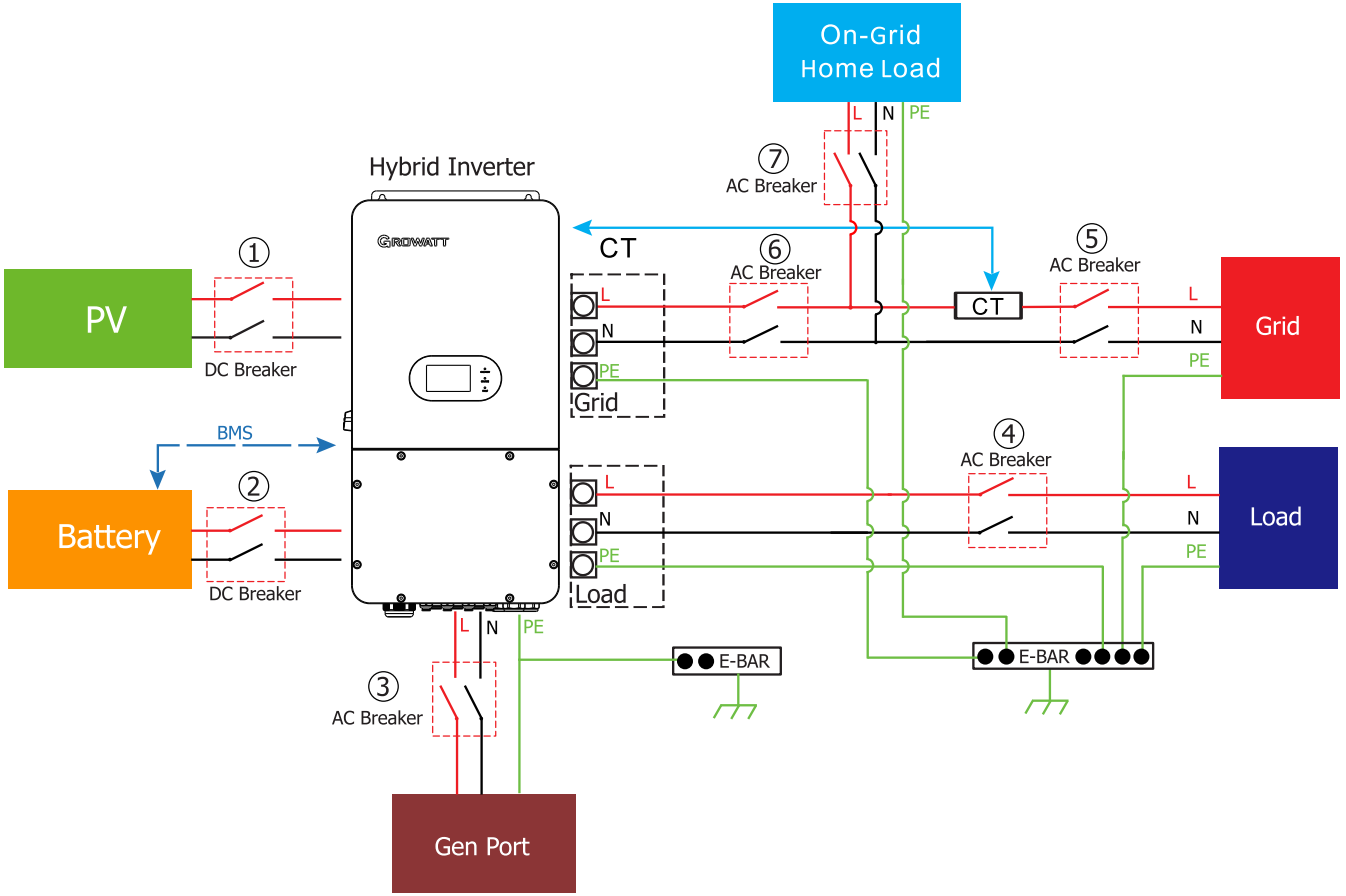
I'll certainly report back if I hear anything. It is perhaps only fair to post the other schematic from the manual which depict double pole MCBs and no link. I thought I was asking an easy question.
-
Earth Neutral bond for hybrid inverter (again)
jimseng replied to jimseng's topic in Photovoltaics (PV)
I don't have a grid connection yet, but I will have. Maybe not until later in the year. I think the schematic is not really correct. I think the permanent neutral link is for other countries. I was under the impression that the neutrals are common until the grid goes down, at which point the grid is disconnected internally with a double pole relay, hence the need for an earth neutral bond relay, but it is hard getting the information. I have reached out to Growatt, I'll see if they come back to me. -
Earth Neutral bond for hybrid inverter (again)
jimseng replied to jimseng's topic in Photovoltaics (PV)
Even if the link was in the grid somewhere, isn't it electrically the same? The trouble is it probably covers different countries and is a bit generic. I am wondering what UK people think. The Sunsynk manual has the same schematic.