Jammy5
-
Posts
66 -
Joined
-
Last visited
Everything posted by Jammy5
-
We don't get an option. It's 25mm with United Utilities. They want to see it at the garage door threshold, so I'd have to fit a reducer under the garage floor and then back fill, which I don't really want to do in case there's a leak? Or is this normal stuff in this day and age? Unfortunately regardless of this, they will then see the 32mm pipe coming up in the garage where they fit the water meter (apparently all water meters are now installed inside the property). So it kind of defeats the object anyways of hiding the fact I'm using 32mm pipe. I just need to convince them that I can keep the 32mm pipe fit reducers to the connection outside and inside, and then ensure it's installed 750mm down from the garage door for their viewing by digging down. Unless I'm missing anything obvious? Thanks for the replies so far though
-
So current thoughts are to dig the front of the garage so the pipe is 750mm and under dig the concrete slab slightly. So the only part that won't be 750mm deep now will be inside the garage. I don't really want to relay the pipe in the garage as it creates an issue in trying to repair the DPM. I'd then have to find a 32/25mm reducer to connect to the boundary box so it's a 25mm connection for the water board as we've been told it must be 25mm (I'm hoping they accept my arguement that the pipe between box and my garage can be larger). Any thoughts?
-
Morning all, Firstly I'm learning on the job here and will have made a few mistakes trying to manage the build myself (never again). So, the issue I have is I mistakenly ran 32mm MDPE instead of 25mm for the mains water supply. I also didn't run it at the correct depth as it enters the building (it is under the DPM and 150mm slab in the garage though but definitely not 750mm deep) and didn't insulate it. It enters straight through the garage door opening, so not drilled through the wall. Am I correct that my only option is to install a new mains water pipe? The predicament I find myself in is there isn't alot of remaining space to dig a trench but I'll have to find a way. I intend on running a 100-110mm insulated Flexi pipe for the job with the 25mm internal Secondly, and the part I need advice on is how can I bring the pipe into the integral garage? Concrete slab is down and DPM laid (I'm at roof truss height). I'll have to disturb the DPM as I create a hole in the garage floor as small as possible but how do I repair the DPM once I have the hole dug/drilled and pipe laid? Also, is it fairly simple to patch the concrete in? Anything specific I need to consider? Any advice on this would be much appreciated. Kind regards, Jamie
-
Characteristic Situation 2 and Gas Membrane
Jammy5 replied to Jammy5's topic in Surveyors & Architects
Just having a think on this one as well. Do you have to follow recommendations? It doesn't mandate the need for one. -
Hopefully this will be my last big stumbling block and advice would be appreciated. I have noticed in my ground investigation report that it states:- The results of the ground gas monitoring indicate low levels of ground gas that do not warrant gas protection. However, given the presence of elevated gas concentrations and shallow coal mine workings beneath another nearby development, it is recommended that basic gas protection measures in line with Characteristic Situation 2 (CS2) are included as part of any proposed residential properties to protect any future residents from any ingress of Carbon Dioxide and Methane. The site is not at risk of radon gas and no protection measures are deemed to be required. Earlier in the same report, in amongst the detail it states:- Therefore, in accordance with CIRIA C665, Table 8.5 the GSV for CO2 equates to a Characteristic Situation 1 (CS1). However, given the previous reports for the opposite site and the presence of shallow nearby coal mine workings, it is recommended that basic gas protection measures in line with Characteristic Situation 2 (CS2) are included within new builds. The report found that the maximum recorded CO2 concentration, which has been converted to a Gas Screening Value (GSV) was 0.0025 l/hr GSV. It also states that since no concentrations of methane have been recorded, no GSV can be formulated. BS 8485:2015 + A1:2019 has a scoring system for gas protection. The uncertain part is how to interpret the recommendations from the report. Can I consider my CS by Site Characteristic as CS1, as the L/h is <0.07 when working out my minimum gas protection score? If I have to work with CS2 and a type A building this would give me a score of 3.5 which I wouldn't easily be able to adhere to with having a ground bearing slab design that has already been constructed - I have currently constructed the walls to DPC level and compacted the Type 1 hardcore, ready to add a sand blinding and cover with a gas membrane. What I would like to understand is do I actually need to install ventilation or is the gas membrane without ventilation sufficient in this case. Especially with the report classifying as a CS1 but stating to apply basic gas protection measures in line with CS2. I'm hoping this means take the score as 0.0 (instead of 3.5) but put a membrane down that is suitable for a CS2 situation (without the need for any ventilation as my site is classed as a CS1). Hopefully I'm reading the standard wrong or missing something and someone can offer their opinion on the matter. Thanks in advance.
-
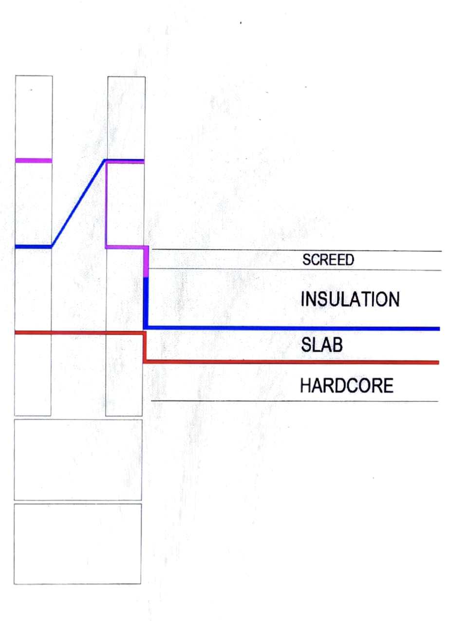
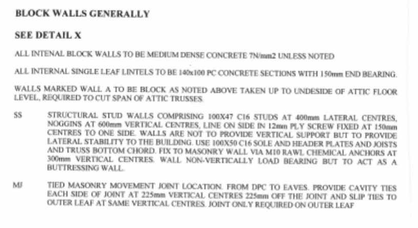
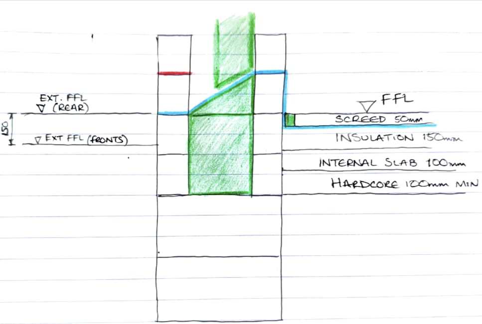
Thanks so much. In fairness that's very similar to what the guy I know is recommending. Just a couple of questions please. What's the vertical yellow line? And what are the lines above the screed? Is this just showing the flooring finish and skirting? I'm assuming the red is the gas membrane and there's no additional DPM needed anywhere? I've been recommended to run a belt and braces, standard DPM above the ground floor slab (below insulation) which would finish to the top edge of the second block (inner leaf only). Would this be required? I'll give my visqueen rep a call. I really do appreciate the help with this one.
-
Thank you for the reply. You have shown FFL at the correct height but FGL1 is the same level as FFL (needs raised 1 block). Unfortunately, I have already installed two blocks above the trench blocks (up to FFL) and the compacted hardcore is already in place. I have also gone for a traditional slab rather than block and beam. Sorry if I wasn't clear above
-
I'm on my mobile or I'd have looked to remove names etc from the drawing and then post. The two details attached are from the architect (mentioning DPC) and the structural engineer which is void of any mention of DPC or detail. The only difference is I've gone with a traditional slab and the external ground floor is as mentioned above.

-
Ok, I understand what you're saying. Everything was paid for via my architect, so he was the one co-ordinating it all, but he's barely communicating. It took me two weeks of chasing to get electronic versions of the drawings out of him. I just feel quite stuck with this one at such as important stage really.
-
A structural engineer has had input. No mention about DPC or anything as such in his details. Is it a structural engineer that would advise on these things? Sorry for all the questions
-
Thanks, I've put this concern on the back burner. Appreciate the feedback all
-
I'll post shortly but I've basically built two trench blocks and two blocks up (both inner and outer leaf) on the drawings above. I've also laid and compacted hardcore ready for a blinding of sand
-
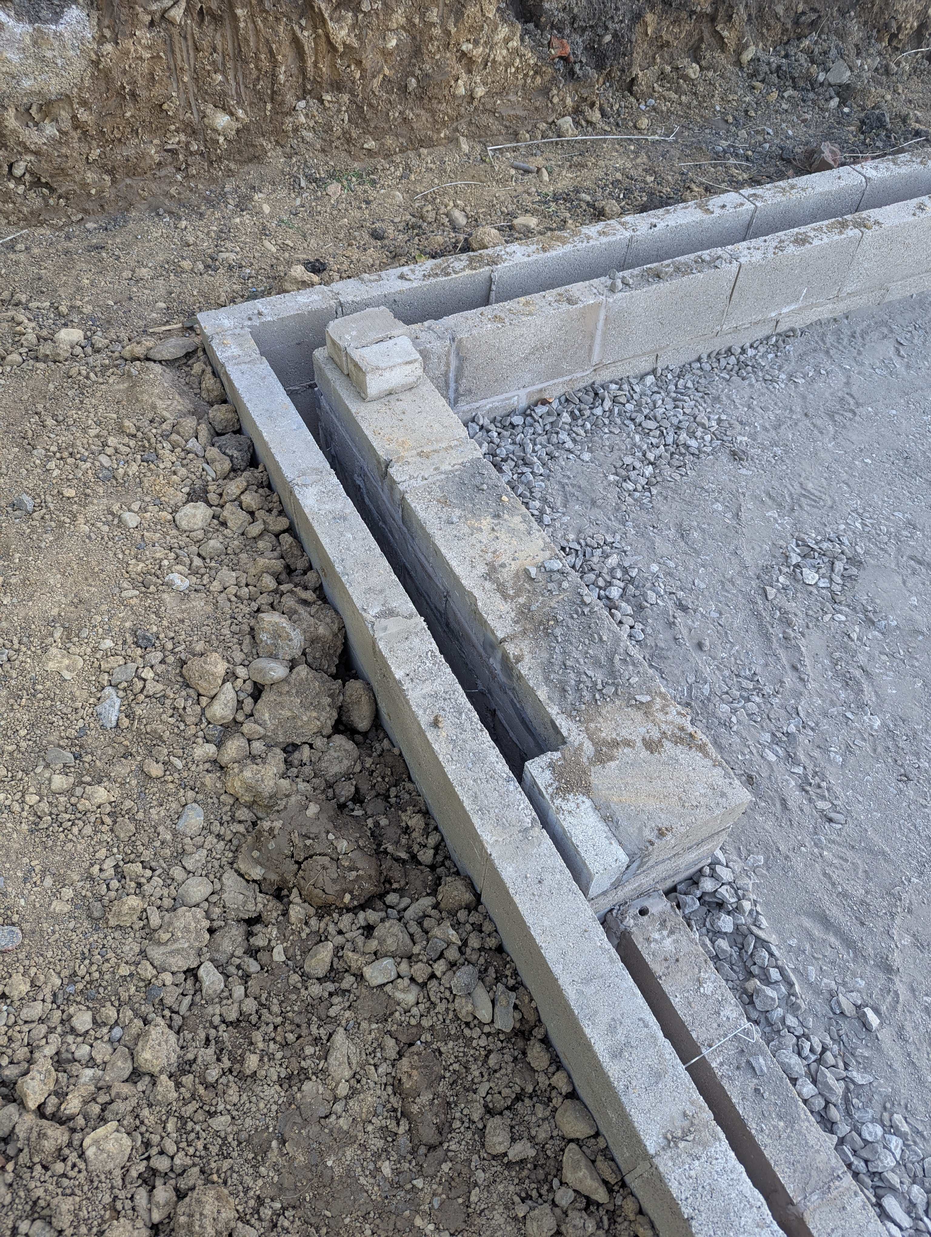
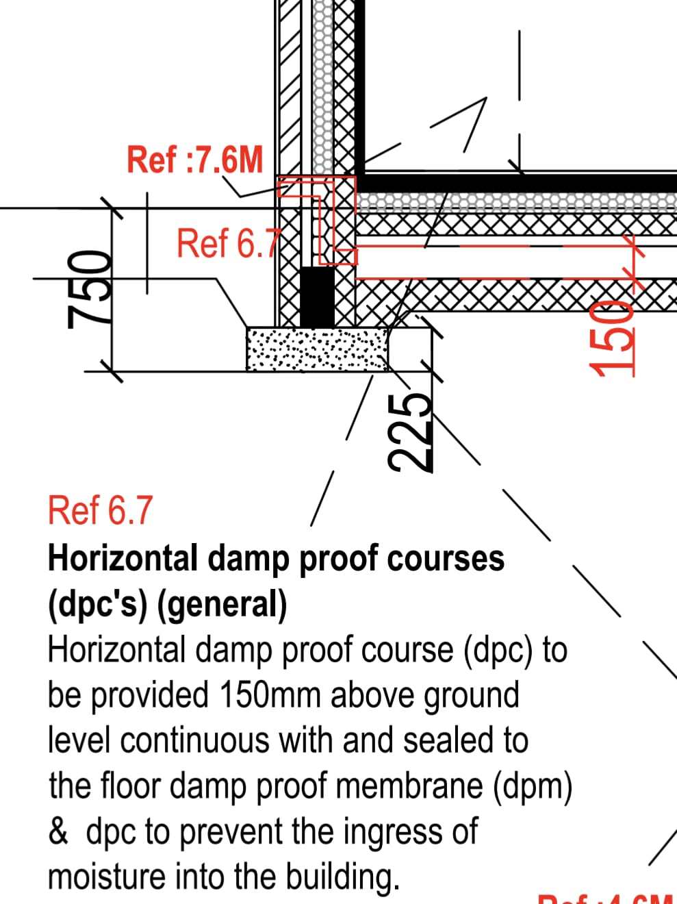
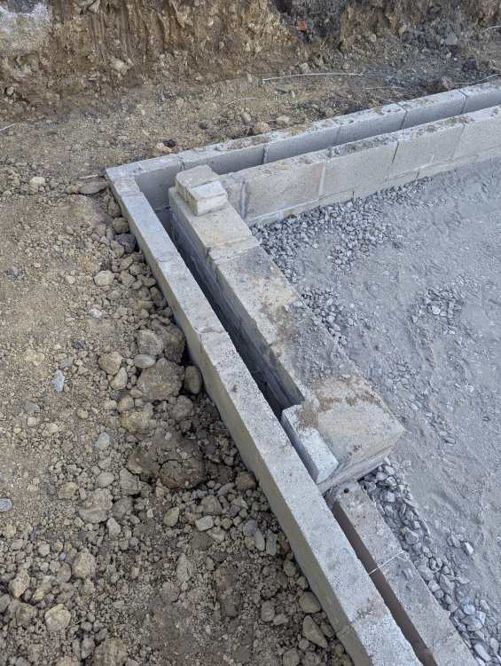
Hi there, I'm hoping people on here can solve a really bad head. I'm not getting much joy out of my contracted architect, so thought I'd see if anyone is able to help as I'm really going round in circles with this one. I received my SAP calculation package and within it, it states that "Recognised Construction Details (RCD) for Masonary Construction to be used and followed" as per the following: www.recognisedconstructiondetails.co.uk/walls/masonry-cavity-wall-partial-fill-insulation The specific area thats causing me a problem is the detail regarding the DPC/DPM which is:- MPF-150-E5-12-Ground bearing slab_ insulation above In addition to this, I also must install a gas membrane that spans the cavity. The finished floor level (patio) along the back edge of the house (9.5m wide) will be level with the internal finished floor level. This will then slope from front to back (13m long) to ensure the front face of the house is 150mm below the internal finished floor level. Obviously the issue being that I do not have a DPC 150mm above ground level. I plan on installing an ACO Slot Drain along the full back edge of the house (this elevation has a single 6m wide bi-fold door) but this leaves the two sides non-compliant with a slope running from +0 to -150mm below along a 13m length. The below are my thoughts on how I could achieve the Recognised Construction Details:- Figure 1 Figure 2 Figure 1 has the DPC at ground level on the whole rear elevation and less than 150mm along the side elevations. To combat this I’ve added a second DPC (shown in red) a block above. Figure 2 is as per the recognised construction details but I’ve simply raised the DPC up by a block on the inner and outer leaf. This would mean the internal is 450mm above my internal finished floor level but I would achieve a minimum 225mm above external finished floor level (with it being 300mm on the front elevation). I also plan on installing on standard DPM under the slab and bringing that up to the top of the second block on the inner leaf (finished floor level). Which of the two is the best option? An architect I know, really dislikes the Recognised Construction Details. Their opinion is the DPC should be flush with finished floor level and should not run down the inside of the inner leaf, above the skirting board. He is arguing that in practice there will be mortar droppings into the bottom of the cavity tray which will block the weep holes, and water will rise up the cavity tray and eventually lead to damp down the internal wall. As a compromise, he has recommended a different detail which wraps a block on the inner leaf. The purple is DPC, the red is the gas membrane and the blue is a normal DPM. There will also be a vapour barrier installed as standard above the insulation which isn’t shown. The detail is shown below:- Figure 3 My main issue with this, is I am already two blocks high, above the trench blocks, and would mean removal of a course of blocks or three bricks to install the gas membrane. I also wouldn’t be able to complete the full fill insulation as detailed and in theory isn't following the recognised construction details. Are the recognised construction details really that bad if I follow them as per one of my two details above? Sorry for the length of this, but hopefully I've explained it well enough. Many thanks.

-
Sorry for the late reply. There's no doors on the elevations that are 600mm away from boundary (1200mm gap between the two houses), but there are two windows. Both windows are over 1m2 each checking the building control approved drawings. The home is three story build, and every room is fire compartmentalised. I assume this is what allows more than 1m2 of total glazing on this elevation? Or is it because one is a bathroom window?
-
I'm measuring from the wall so I'm aware there's potentially another 100mm or so to lose because of eaves I'm also aware the fence that I'm measuring to might not be on the boundary line. My concern was how picky will they be when we're dealing with 50mm here and there when we're talking about a 2500:1 scale drawing from land registry? I could always put a fire check external door on the side to compensate if needed. The window sizes are also above the recommended but again have been passed by building control so I'm going to progress with the build as identified on approved drawings.
-
Hi all, I've just found this forum after days and weeks of tearing my hair out weighing various things up to find they're generally answered here!! So my question is.... My property has been marked out in accordance with building regulations on one elevation (1m) and then the other elevation meets the other home that is being built (2 plots side by side). There is a shared access way between the houses of 1.2m. This is reflected on site plans that have been submitted by the architect to planning and building control. However, without knowing how a shared access way is viewed by building control, then my concern is that I'm closer than 1m to the boundary (in theory bother houses will be 0.6m) The architect is working for both of us but isn't the most helpful to have this conversation with. Any insight that would put my mind at rest? Many thanks in advance, Jamie