
yellowbert
-
Posts
16 -
Joined
-
Last visited
yellowbert's Achievements
Member (3/5)
1
Reputation
-
@G and J - Thats exactly it - The SE had indicated that we were limited by the invert levels. Ideally the poo pipes will go down and then run completely below the insulation so we dont have to compromise on having a thinner layer of insulation over the pipe itself - PIR could definately help us here too. We have been super lucky with the architect. Originally we had a not so great one, which didnt last very long. Our architect now is excellent and very knowledgable regaring the passivehaus side of things in particular - The advice for quicker response times had come from one of the UFH manufacturers directly - interestingly because they specialised in those kind of quick response systems.
-
Thanks everyone for all the helpful input. It looks like we are going with a standard solid concrete ground bearing slab with strip foundations as long as the SE doesn't have any additional worries with this setup. It does look like we might need to locally reduce the amount of EPS insulation where we need to run a soil pipe but hopefully this wont be an issue. @Nickfromwales - I notice that there was PIR rather than EPS in the build-up you mentioned above. Are there any additional considerations or precautions needed if using PIR below the slab? This would possibly help us to reduce the thickness and possibly remove the need for running the soil pipe within the insulation layer.
-
@JohnMo - Absolutely - and making the required excavation deeper with more cost there too. I've spoken to the architects today and they are happy with using just the structural concrete without a screed. It looks like their initial spec was to provide a more rapid response. @jack - Architects are totally happy with this now - and I feel like this is definately the best solution for us with Insulation and airtightness at Enerphit levels. Thanks also @Nickfromwales - Although I suspect we are going to go for a tiled finish mainly due to cost, Polished concrete is still an option if its affordable and great to hear that it works well with this setup.
-
@Nick Laslett - Thanks Nick - Yes, I think the architects are favouring this option - although a standard concrete slab ground floor with strip foundation has also been approved by the SE - so essentially both options are still on the table. Thanks for the link regarding the passive slab - thats super useful. This in particular would definately be very important - the existing house has only brick footings with no concrete foundation at all. If we go for the strip foundation and slab - then the new foundation would be at the same approximate depth as the existing footings which is good - whereas the Raft would end up being deeper. @JohnMo - Yes, from what I've read so far, this was exactly my thoughts - so it will be useful to understand what the architects were intending with this - We have a meeting next week so I'll hopefully be able to update things then 👍 If they suggest keeping a screed layer to ensure having more control over FFL, I guess it would be fine to have the UFH within the concrete slab then the screed layer on top without the intermediate layer of insulation?
-
Thanks @JohnMo Up until about 5 mins ago - we didnt know - but structural engineers have just given us the concrete thickness as below. Concrete Thickness: If using a Concrete Slab = 150mm If using a Raft Foundation = 300mm In theory both options are open - I think the architect would like to go with the raft as they can reduce the thermal bridges to almost zero, but as it will almost definately cost many times more than the standard concrete slab, its likely that we will probably be forced to have the standard concrete slab. In terms of the screed layer - I'm not sure how thick that would be, but I'm guessing as this will be non structural it would be in the region of 50mm to 75mm max. The architect mentioned the screed could possibly be seperated from the slab/raft with another layer of insulation although they haven't yet indicated what thickness that would be if used.
- 17 replies
-
- 1
-

-
- ufh
- raft foundation
- (and 3 more)
-
I know this has been answered for similar questions but wanted to ask it in a slightly different way as I can’t find an exact answer to my query. We were initially expecting to have a suspended floor, but Structural Engineers have now confirmed they are happy for a ground bearing solution after receiving our soil test results. The build-up that has been suggested by the architects is, from bottom up: · Approx 300mm EPS Insulation (approx. U = 0.1) · Reinforced Concrete (either as a standard slab or possibly a raft foundation) · Thin layer of insulation · Unbonded Screed with UFH pipes embedded (Base layer & DPM omitted in description to focus on thermal aspects) My questions are: 1. Should we be embedding the UFH pipes within the unbonded screed as in the build-up above, or should we do away with the screed layer and place the UFH withing the concrete as many on this forum have done? 2. Does that answer change depending on whether a standard concrete slab is used with a strip foundation vs a raft foundation. We are talking to the architect again next week so will hopefully have a better understanding of why they have suggested this build-up and it would be great to get your thoughts so we have some info going into that meeting. For info - the build is part renovation and part extension aiming for very low heat loss EnerPhit standards with new insulated ground floor everywhere. Thanks everyone
-
Trying to understand Heat Loss and UFH options
yellowbert replied to yellowbert's topic in Underfloor Heating
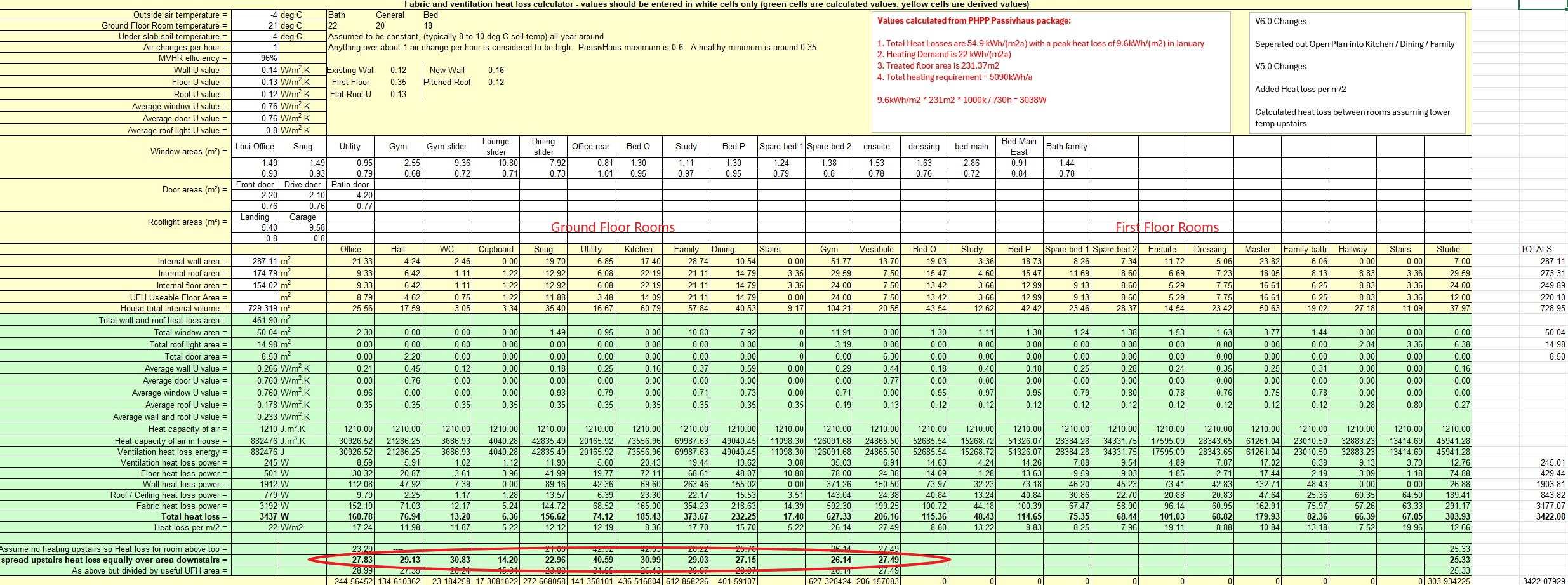
Thanks again @JohnMo - I orginally used the 1 ACH for the calcs and then changed it to 0.6 for my latest few versions of the spreadsheet although these arent shown in the screenshots above. All the UFH spacing on the graph above come from the figures using 0.6. I have been using LoopCad also - but was struggling to make sense of how to get the wall, ceiling and floor buildups exactly what I wanted. The results came out pretty similar tho which was good. -
Trying to understand Heat Loss and UFH options
yellowbert replied to yellowbert's topic in Underfloor Heating
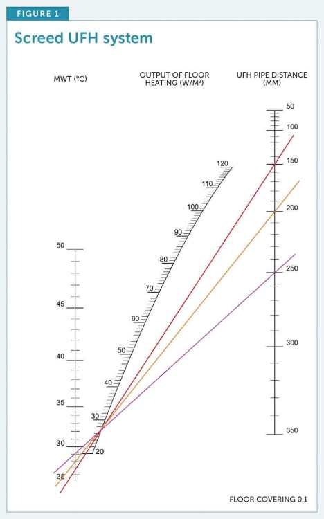
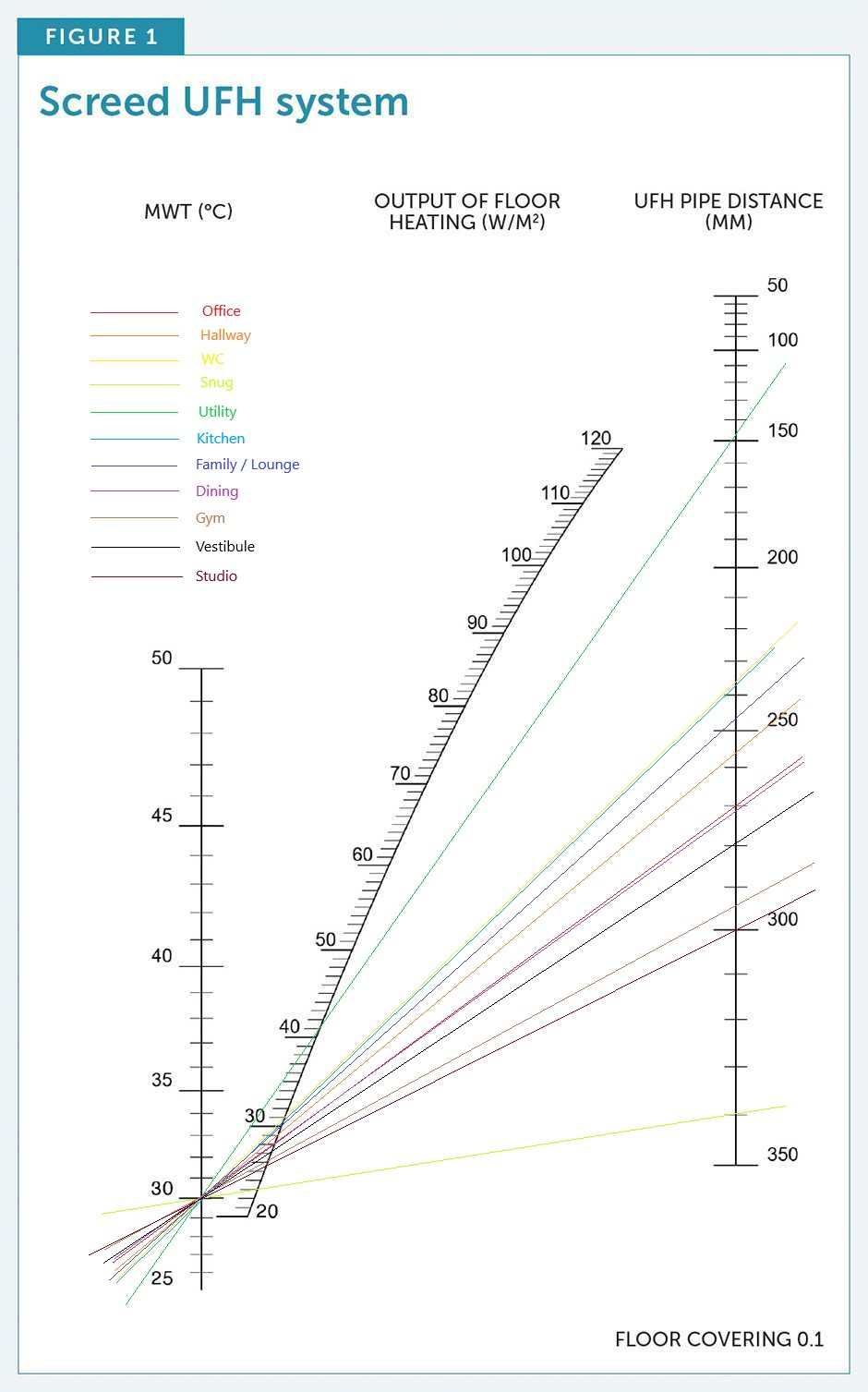
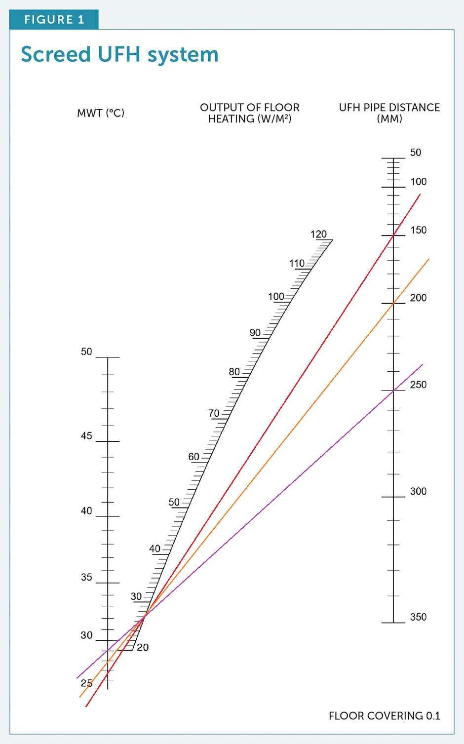
5. With these heat loss figures I then calculated the required UFH spacing for each room using the graph that @JohnMo posted earlier. I assumed a Mean Water Temp of 30 degrees. The 2 outliers were the Utility room and the snug. The Utility room has a small useable floor area for UFH so needs tighter spacing. The Snug is a bit odd - and might need another look, but am assuming that the wider spacing is down to the relatively large useable floor area and the fact that there is only 1 small window.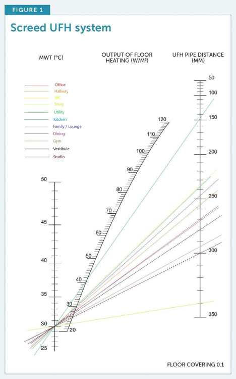
-
Trying to understand Heat Loss and UFH options
yellowbert replied to yellowbert's topic in Underfloor Heating
3. I then accounted for the different U values in different parts of the house so that the individual room calcs reflected reality. 4. As we are likely to have no heating upstairs (will likely fit it but hopefully not use it) – I then added another row to the spreadsheet to calculate the Heat required from the UFH in each ground floor room so that it was able to account for the heat loss in its own room as well as the room and warm loft above it.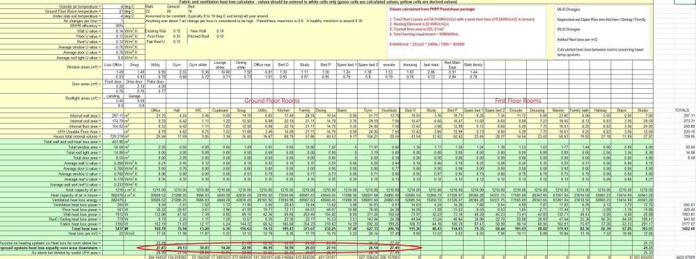
-
Trying to understand Heat Loss and UFH options
yellowbert replied to yellowbert's topic in Underfloor Heating
As promised – I wanted to share the stages I worked through to calculate the individual heat loss from each room and the required pipe spacing for the underfloor heating in case anybody finds it useful: 1. I used Jeremy Harris’s Heat Loss spreadsheet to calculate the Whole house heat loss using average U values at this stage rather than individual U values for each type of roof and wall buildup 2. Once I was happy that the whole house calculation was as accurate as it could be – I used the same spreadsheet to create an extra column for each individual room. Initially I also used the average U values so I could be sure that the sum of the heat loss from each room was the same as the whole house. The results were a few W out, mainly down to internal wall measurements and slight rounding errors.
-
Trying to understand Heat Loss and UFH options
yellowbert replied to yellowbert's topic in Underfloor Heating
Thanks @Temp - that is also a great point - perhaps fan coils for most of the upstairs on the same zone as the UFH on the ground floor - with some supplementary electric UFH for the bathrooms which can be linked to a timer / stat - that would give us the efficiency of a single zone for all the plumbed in heating but the flexibility of having heating in the bathrooms when everything else is off. I think I'll work through the individual room heat loss calculations, which may take me some time - I'll then share my workings on here which should hopefully be helpful for anyone else trying to work through the same process of designing their own heating system. I'm sure I'll make lots more mistakes on the way. -
Trying to understand Heat Loss and UFH options
yellowbert replied to yellowbert's topic in Underfloor Heating
So if putting UFH or fan coils upstairs on the first floor - would you do this on the same single zone as ground floor or as a separate 2nd zone? -
Trying to understand Heat Loss and UFH options
yellowbert replied to yellowbert's topic in Underfloor Heating
Thank You @JohnMo - this makes more sense than trying to hit the very lowest flow temp for that 1 coldest day. And just to confirm - when you say design flow - thats referring to the ASHP flow temp rather than the mean temp of the flow and return? -
Trying to understand Heat Loss and UFH options
yellowbert replied to yellowbert's topic in Underfloor Heating
Thanks @SteamyTea - To be honest this is something we are a little worried about - PHPP calcs that the architect has done shows there won't be any problems, but it's a big leap of faith to just trust the numbers - a bit like trusting that we won't need heating upstairs! In addition to looking at shading some windows I'm starting to think it might be worth installing either UFH or fan coils or similar upstairs so that we have a method of heating if needed but also to actively cool in the event that rooms do over heat on those really hot days. That's also an excellent idea and won't cost much for the peace of mind that we can add the panel heaters if we need to in the future. @SteamyTea - This is exactly the kind of thing I'm not looking forward to quite so much as the other work - one of the things that scares me the most is shifting several tonnes of bricks as I'll likely have to do a lot of the demolition work myself to save cost 😬 -
Trying to understand Heat Loss and UFH options
yellowbert replied to yellowbert's topic in Underfloor Heating
Thanks @JohnMo that makes a lot of sense. So it would be better to do individual room heat loss calcs so that I can find the optimum pipe spacing for each room rather than having the same pipe spacing throughout. Once I know the individual heat loss for each room I can then use the graph to determine pipe spacing for various mean flow temps and I need to make sure that I don't go below the min flow temp of the ASHP. e.g If the min flow temp for the ASHP is say 25oC - should I aim to get all the way down to this with an appropriate spacing? I guess these calculations are all for the worst case coldest day - so would you also do the same calcs for the shoulder months to make sure the flow temp on those days is also above the min flow temp for the ASHP or does that not matter? Thanks again - Hoping to gradually understand this as its such an important part of what we are trying to work towards in terms of a relatively low energy renovation.