Peaklander
-
Posts
46 -
Joined
-
Last visited
Everything posted by Peaklander
-
Yes that’s exactly what’s happening with the pump-over. Hot going up the vent and down the cold feed. Everything is hot up there. Ok I can do this. I can see that the PP2 curve should give a lower pressure at reduced demand.
-
No just from the description given:
-
Totally distracted atm because we are babysitting three grandsons who are not yet in bed. One thing that is now clear is that water in the ‘cold feed’ moves up as well as down.
-
Hi, thanks for the ongoing advice and comments. After plumber #1 had visited and then couldn’t return for a week, I managed to get the radiators hot by a combination of new pump, some bleeding and a little bit of lock shield adjustment at one radiator. Later, plumber #2 advised a flush and fitting of a mag filter. When we refilled it was very hard to get the air out and good circulation but eventually we did. That was done on 21/12 and the heating has worked since then but with venting. The boiler temp has been decreased and it modulates nicely although the temperature is still quite hot at the radiators, which is a little surprising. Today I managed a quick visit and tests that have been suggested. With HW only, there was little change. I didn’t leave it long but nothing obvious happened and venting continued. Switching the pump to ‘constant pressure #1’ caused immediate increase in the water over the vent. This was inspite of the pump sounding slower. So I reverted to ‘constant curve 1’. That’s how I have left it. I’m now wondering if that 150mm pipe between the vent and feed Ts is the culprit. Hopefully plumber #3 will listen before giving advice. Edit. I will reiterate that I don’t know when the venting began but it may well have been since the new pump. The header didn’t have a lid, just a loose fitting bag of insulation and the condensation in the loft was excessive.
-
I still don't understand what's supposed to happen. The pump sucks and creates pressure downstream, pushing hot water around the circuit. This returns to the boiler and is reheated (and expands?) and comes back to the H pipework where it tries to go up to the vent but is sucked away by the pump. Does the pump pull cold water from the cold feed? If no, why doesn't it? If yes, is that to make-up for expansion? What happens when it cools back down?
-
I'm not there so it's a guess. Ceiling is more than arms length up, so say 2.4. Header is sitting on joists so not much higher. The 150mm pipe between V & C is about 1.0 above floor. So I'd say 2.4 - 1.0 = 1.4m to header and maybe 400mm over the top of the hockey stick. So 1.8m maybe.
-
The pipework is 28mm. You can see the reducer to 22mm on the pipe to vent. Also this system has been in place for years and the venting must be fairly recent. So it isn't a basic design / height issue.
-
That’s what I find most confusing.
-
No, I meant that the original pump and its replacement were/are both pointing down towards the zone valves. It was in response to an earlier comment.
-
Interesting and thanks @John Carroll I don't have a pic of the header but there's only three pipes - the 22mm vent, cold water feed down in 15mm and a cold supply to the ball valve. Whilst I don't know about LLH I am pretty sure that this is a conventional header but I will do some research. Now to the pump; I can't say that the CH was venting when on the old one. Plumber #1 had been (without me there) and advised changing the pump as a first job. He couldn't do it for a week and so I did it. In that week when plumber #2 came with a toolbox of moral support, he noticed the venting and we have moved from that position. So that setting of CP1 you suggest is definitely an option that I can try / have in my suggestion box, when plumber #3 comes on Friday (I can't be there again until then). I know how to approach conversations with 'the trades' and it won't start with "I read on the internet"!
-
I'd like to keep this thread alive until it's fixed. I nipped to the parents' this morning. The boiler is happily supplying CH, on low flame and things are warm in all rads. There is a steady, small flow up through the vent and back down the cold feed. I didn't have time to do the suggested test with HW on and CH off but I can see that it would probably give some pointers as it eliminates all the radiator circuits. I don't know where the two returns join and I suppose there could be a restriction in the common return back to the boiler but that test seems to be a good idea. Also I have contacted another plumbing company and a guy is meeting me on Friday morning - so more news after that I hope.
-
@Mattg4321, how did you diagnose the blocked exchanger? I don’t think that’s the problem here because a lot of heat is getting transferred to the rad circuit.
-
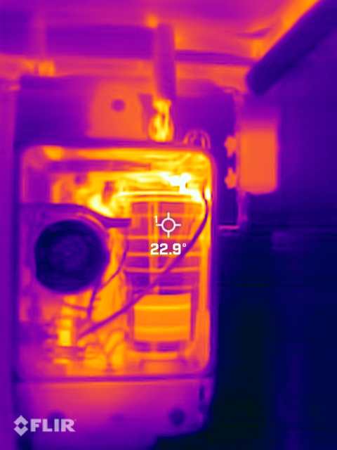
Thanks. On the marked up diagram it’s the flow from the boiler but otherwise OK. Yes it’s a Greenstar Ri I have a pic of the hex which I think shows it’s OK The pumps are both pumping downwards. Yes a slight pressure in a sealed system might be ok. Maybe I should do a longer flush I still don’t know why a restriction would cause venting. The reduced flow would be all around the circuit, unless as I say, this creates a back pressure at the pump. Hmmm Edit: Oh and I don’t know about the DHW only. I will check but not until Wed now.
-
No-one? 😢 Anyone with any advice?
-
Gas Boiler Flow and Return Pipes In Copper?
Peaklander replied to tuftythesquirrel's topic in Boilers & Hot Water Tanks
Hi, I don't frequent this forum often enough but visits are getting more frequent. So forgive the question but can you point me to more detail about what you said? Thanks -
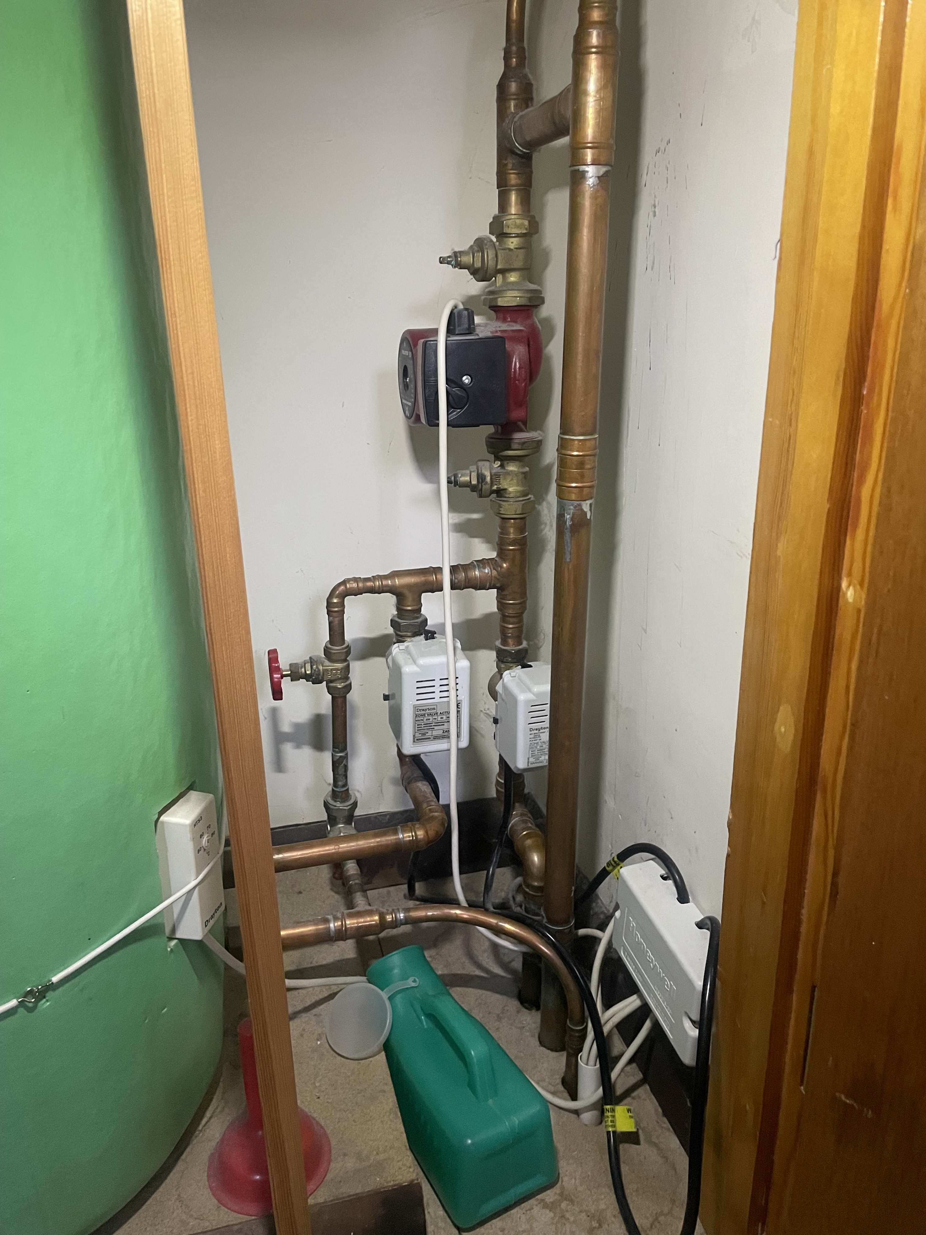
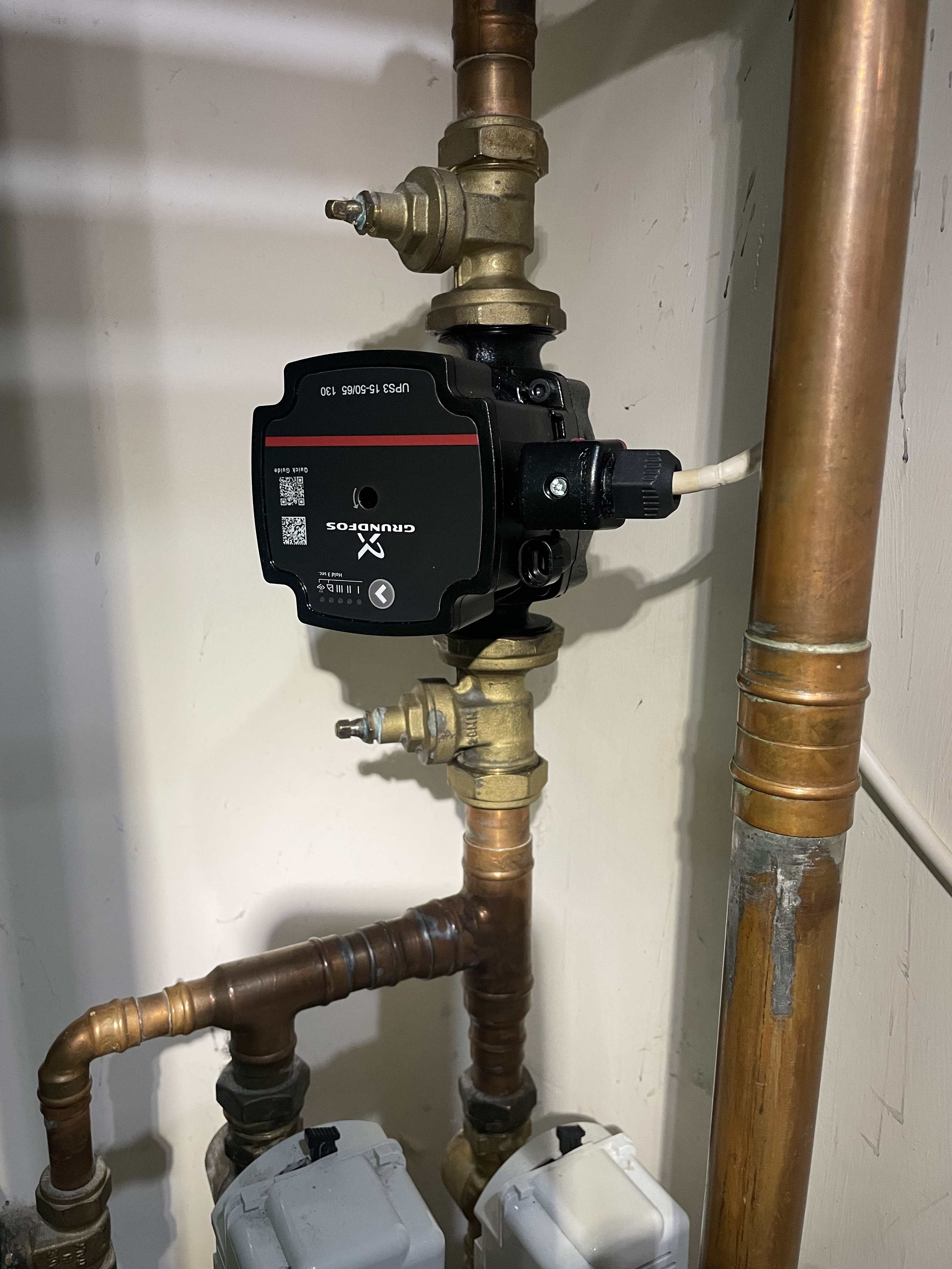
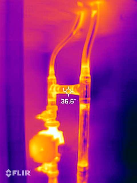
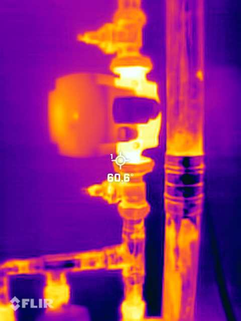
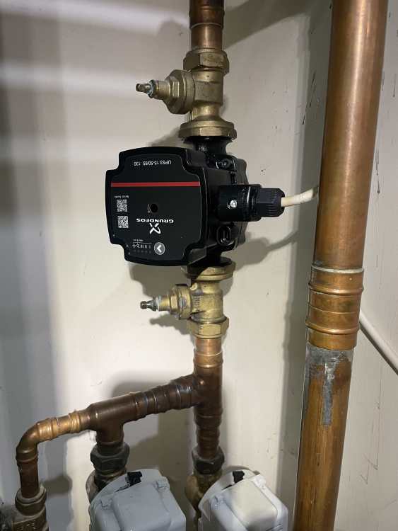
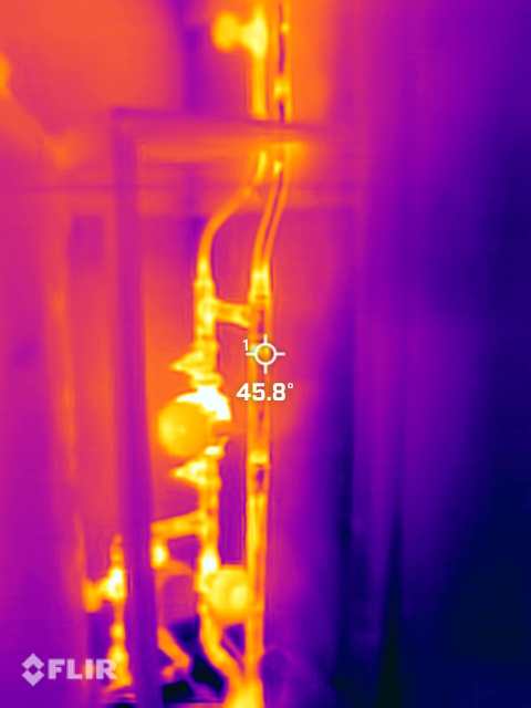
Hi, As per title, we (well my aged parents 97 and 89), have a regular boiler (Worcester Greenstar) feeding DWH through a thermostat-controlled zone valve and central heating to the house, again through a zone valve. There's a large header for the HW and smaller one for CH and the main flow pipework to the pump is in 28mm, with 22mm up and 15mm down from the CH header. This installation has been in place for many years but some weeks ago a visitor noticed that 'some radiators need bleeding'. A plumber did this but said that he couldn't get sufficient flow around the system, suggesting there was a faulty pump or airlock. He was unable to return for a week and so I went (at least they are local to me) and changed the pump myself for a nice new UPS3 15-50/65. Nothing instantly improved, until I bled a radiator and also turned a lockshield down. Then the rads got hot. However I had already got a second plumber lined-up when the heat finally happened and he called to have a look anyway (moral support). He was happy that heat was available but had a look around, didn't like the feel of the zone valves or the lack of a magnetic filter, so we agreed that I would purchase these items and he would come back to fit. When he did, along with Fernox system cleaner, we could not get heat to flow - so it was just as before. The rads only got warm and the boiler kept tripping. Eventually we bled air more, including at the top of the boiler and we got heat. He looked at the header tank and showed me that hot water was coming over the vent. The level was ok so the pump was drawing from the cold feed. Maybe this has been happening for days. Since then nothing I have done has stopped this. We did a basic power flush (plumber has a pump / tank set-up with magnet that recycles the water) and made a reasonable job of closing rads one by one (with the vent pipe capped). I have: - experimented with the pump speed and it's now down at 1 - reduced the flow target temperature (and can hear the boiler immediately modulate down) - taken infra-red pics of the H pipework, where the vent and cold feed are tee-d into the flow pipe, just before the pump. Plumber says there's a restriction in the radiators or flow / return circuit and he wants to move to a pressure system to try to drive it harder. (Removing the header and replacing with an expansion vessel, PRV and a cold fill point). I am hesitating to move off gravity because there are buried pipes at ground floor and I wouldn't want to find some leaks with the pressure. I think that for hot water to rise into the vent rather than go into the pump, the short pipe between vent and cold fill must be restricted. However this is 28mm and it feels hot. Maybe it is conducting heat from the pipes and there's little flow through it. I have tried to photograph but with the IR it's quite an art to get the correct colour temperature range and maybe too much can be read into them. I'm reluctant to cut into this (with a view to replacing with a 28mm compression) because I don't know how to make two clean cuts and also not sure if the pipes will move enough to get the fitting in. Soooo, to my questions... 1. If there is a restriction in the circuit, isn't the pump return pressure going to be lower going out and back and so it would not send water up the vent? 2 Or, even on speed 1., does the delivery pressure against a restriction, increase pressure backwards through the pump and cause water to flow up the vent, so the pump acts like a sort of hydraulic restriction? 3. Might the short pipe across from vent Tee to cold fed Tee by partially restricted and if so should I jump in there, open it up and see? 4. Should I do more flushing? Have I missed something? Thanks so much - it's a bad time of year to be doing this. Pics attached

-
Battery VAT claimable? Battery choice
Peaklander replied to MortarThePoint's topic in Energy Storage
Did they manage to do this / was there any more advice forthcoming? (and which bit of the Peaks is the manor house in?) -
Newer Velux can be fitted with and insulated collar. The old ones cannot be retrofitted. Also they now have top hung ones which open nicely.
-
I have done a lot of research in preparing for mine. It’s a similar approach and I too will go for 0.16. Are you still looking in here? If so I’ll post-up what we are going to do.
-
Ha, that old Land Rover joke! Mine is a young 28 year old Defender and it’s in prime condition. Much like Trigger’s broom it has had it’s fair share of replacement parts but it has taken us all over and as far away as Greece twice. Thanks for the air tightness advice. I am hoping to do most using gravity as the cavities will be exposed from above. We have had it blown in years ago and none leaked at the bottom. We have suspended floors and so I can see. I have found a few sources but my, they are pricey. Cheapest is £16 for 10cu ft bag.
-
Hi all As a frequent user of a Land Rover forum I don’t know why joining one such as this didn’t occur to me sooner. Anyway, I’m here and would like to say “hello”. I landed on this forum with a Goooogle search that took me straight into the diy blown beads cavity wall insulation thread here. I’d just had a ‘eureka!’ moment a couple of days ago, when I realised that topping-up our existing cavity might be a DIY job. I’m sure that the blown beads installation we did over twenty years ago has slumped. I’ll prove this with a thermal camera once the weather gets colder but you can just feel that it isn’t effective. I live in the Peak District and have been in this house for 25 years but after going crazy sorting it out during the first three or four years, since then it has had plenty of maintenance but no major changes. It’s a 1960 build, two storey detached house with rooms in the roof. Roughly rectangular in shape, we have a 17m ridge and it’s almost 6m ridge to eaves. The eaves are just above the top of the ground floor windows. Why am I here, I hear you ask? Well the cavity top-up is just a minor detail. This is the list of work we are starting in the new year. Strip roof back to rafters Top-up bead insulation by pouring into the cavities now exposed Insulate the roof to U=0.16 with PIR between and above the rafters with breathable membrane and counter battens above Fit in-roof solar panels New roof tiles We also have a longer term plan to fit an un-vented hw cylinder with immersion heater to take power from the solar panels/battery and prepare the pipe work to create zones, to include a new zone to an ufh manifold. Then we will probably lift 60m2 of suspended ground floor, insulate and lay pipe work with biscuit screed. To finish we will lay engineered floor. Hello.