jamesdiyer
-
Posts
83 -
Joined
-
Last visited
jamesdiyer's Achievements
Member (3/5)
7
Reputation
-
Grant/ Aerona ASHP expensive...
jamesdiyer replied to JeffGiraf's topic in Air Source Heat Pumps (ASHP)
I live in a big stone house in equally cold environment. We are doing around 2kw electric input currently at 2C. However we are warm at 20C inside. Contrary to what some people think, it can work very well with the right emittors. If you're flow temps are high but you're not warm, I'd say you have an emitter issue - emitters too small. You need to get a grip on the UFH and why it's not working well - I'd say the landlord should be paying for someone to look at it. It sounds like the whole thing is a mess and needs to be dealt with properly. -
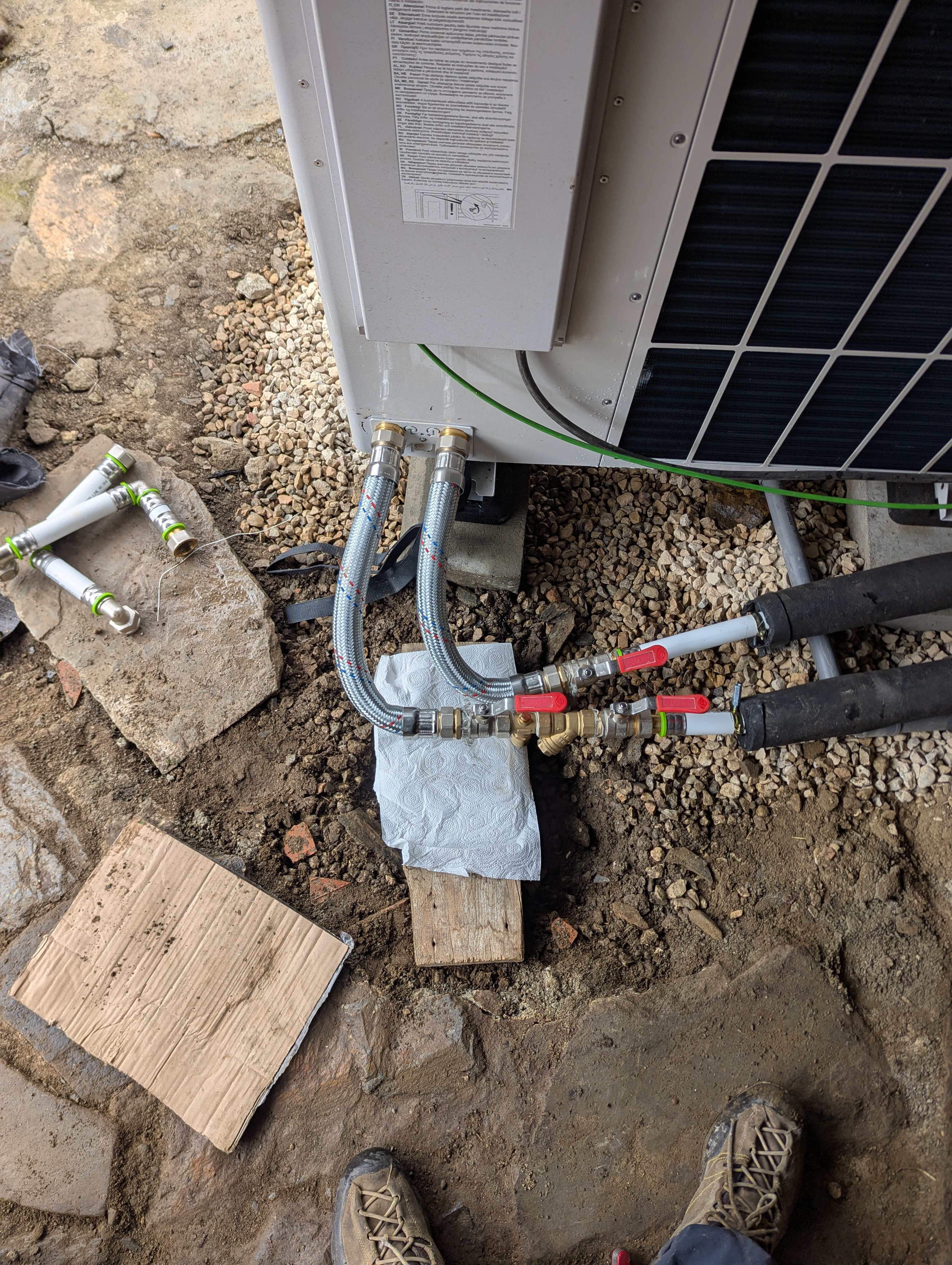
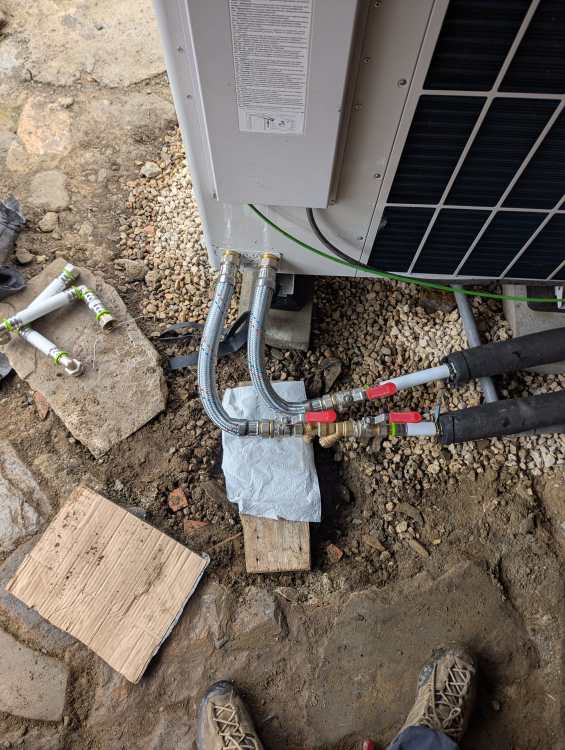
So there hasn't been an update on this as I was hoping the installer would have some decency, sadly they're now a ghost. With it being winter I can't do much. However due to issues with antifreeze being too high and two connections leaking I needed to resolve the situation behind the machine. I took the opportunity to swap the hot mess of 90s to a braided flexi. And as prediction the flow rate went from 1740 to 1860. It's not pretty as the plastic pipe is a bit long but I don't want to drain the whole system to fix it, I'll sort it in the next warm period or properly in summer.
-
We have a 15kW Aerotherm plus. It's the same hardware as the 10kw as far as I can tell - min modulations are the same etc. They also do a three phase version of this.
-
I think for something like that cascade of two machines could be nice. Low modulation for mild temps and can maintain internal temp and a second machine for when really cold. It's going to be really important to get the right design and install done. Different machines modulate to different levels and others cycle better than others. I've an oversized vaillant and it works good. I should have had a cascade setup on reflection though, as the only time we are cold (and not actually cold but not perfect) is during mild temps. The specification pdf on that Panasonic doesn't seem to give a minimum heat output figure at X degrees C, which is what you really want to know to decide between sizes. Without being crass, you're clearly not poor. If I were in your shoes I'd find a really hot installer who knows their stuff and pay them the money to deal with the problem and guarantee it - I'm sure you've better things to do with your time than deliberate this.
-
Noise reduction at 60% doesn't help. So clearly the compression isn't ramping on at that higher rate (power input in still the same as it was without noise reduction around 1600W). I guess this means it's doing a good job of not starting too hard, but I feel it could do better if it started lower % of compressor speed max or modulate down faster.
-
Yes, I feel it's running in that way, and because we have a 15kW beast, at mild temps circa 10C it heats it really quick. But for example, it's 10C out side right now. But with a huge north wind blowing and snowing 500m above the house. So when it cycles off you can note that it's off. Perhaps increasing radiator surface area would help dissipate more heat and decide the increase of return temp. Also I don't think it's a situation of needed to increase weather curve (unless maybe it is) as when it's running and maintaining the flow temp of the curve 0.7, it's maintaining temperature in the house. It's just because it can't modulate low enough and then cycles off. I did wonder about pushing the curve a bit higher so it can keep running, but I think we would then be hot.
-
Thanks for the quick reply and thoughts. Yes I was reading around this but wasn't sure how helpful it would be in this case. I was trying to set up decent monitoring to be able to have data but struggling with that. I don't think it's coming on that strong (I haven't bothered to stand by the box and watch it, but having seen on the app we are hitting ~1500W power input, at lowest compressor speed I see around 950W depending on outside temp. Our unit is quite oversized, while we complete renovations, so we cycle down to 4C. Though we will see -7C overnight quite regularly, and heating off as 15C due to solar gain - so our cycle range of temps is shifted lower. I do think it's cycling well, but if I could get it to pace it's on a bit, I think it might run nicer. I can note the off periods when the temp outside is circa 10C and you can feel the lack of heating I to the house. I guess I could put it in noise reduction mode during the day time and see if it helps. But really I need graphical data first. I would leave it off overnight as we need it to be able to run full to meet potential heat loss at low temps.
-
Regarding the cycling of the vaillant aerotherm plus, has anyone looked into or got information on the power it starts a cycle with? My machine seems to cycle well, however I feel it comes on at a higher rate than needed which pushes temperature up fast, where as if it started at a low compressor speed it wouldn't rap so fast and on cycle would be longer. Maybe it needs the compressor speed to get going and is just how it is.
-
Yes! Exactly.
-
Would you propose using a Flexi to exit the back then? As we need to make a 90deg to enter the building. Perhaps just bend 35mm plastic
-
Interesting. I guess the UFH has it's own pump, and perhaps your rads are lower pressure drop.
-
Maybe I'm way off base with these things and I'm happy to be told I'm wrong. Just trying to find a way forward to best alterations to have a 'ideal' base install.
-
Yes okay thanks for your time explaining that. Looking at a DN32 ESBE 3way, the KVs is 16, so (18.5cV) so the pressure drop would be ~ half or 3.5kpa. I'm not sure that's insignificant. If I'm saying moving from 26mm i.d. to 32mm i.d. primary will reduce pressure from 12 to 4.5 kPa, a reduction of 7kPa.
-
Yes you're right I am. I have seen others mention using bigger 3ways for bigger pipe. I just wondered if it's better the change what's possible, while there changing pipe, than then try come back later and do it. I'm going around on all aspects to decide what I request is changed and what can stay. Because if we change some stuff and can't hit near 2000 then I'm going to annoy the installer - who just wanted to put a buffer in in the first place (but fitted as volumizer on request), so I'd rather get it right second time and hit as needed.
-
also what 3 way diverter are you running? Maybe this should be changed on mine to, while we are making changes.