ricardo100671
-
Posts
38 -
Joined
-
Last visited
Everything posted by ricardo100671
-
Do I need a pump on my manifold
ricardo100671 replied to ricardo100671's topic in Underfloor Heating
Thank you. Not quite sure I understand all that. I am planning to fit the weather compensate sensor, for sure and also have a single room stat. Are these thing mutually exclusive? Assumed the weather compensate would adjust flow temp so we don't overshoot and also be mre efficient -
We will be having UFH in communal areas, 5 loops and 5 rads, in bedrooms. UFH is ProWarm 16mm foile faced routed boards and I have used Heat Punk to calculate the exact rad sizing to run the lot at 45deg C. Will set loop flows to ensure each loop achieves its design output as well all preset lockshield on rads for the same. Our heat loss is about 49W/m2 and so will use a Vitodens 050-W combi. Was thinking I do not need a separate pump on the manifold as, from my calcs, the one on the Vitodens should be plenty good enough, given that it all ground floor, single zone and only 5 rads. Am I mistaken ? Thanks in advance for any help
-
Thanks Nick, for the perfect explanation. Exactly the assurance I needed since this will all be burried so didn't want to do something I would regret. All pipework is either 110 or 50 and the kitchen run is around 2m (excl. Upstand)
-
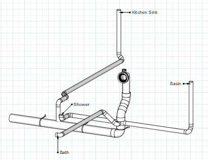
I this design and concerned toilet flush will pull out traps all traps. So thinking to add air inlets, at and, above sinks, but wonder how to deal with low level of shower and bath.
-
Thank you @Nickfromwales, @Lofty718, @ProDave, @JoeBano and @JohnMo for the very usefull comment whcih makes a lot of sence now. The floor is ProWarm Profloor Foil faced 16mm pipe at 150mm c/c, 12mm Laminate about 1.4 TOG. My setup is Rads and UFH will run simultaneously of one stat, so thought 1 Boiler Pump would work, but from the UFH resistive arguments I can see how I will need one on the manifold too. At 45deg the UFH was overshooting by 1000W and I was using that excess to compensate rad shortfalls in adjacent rooms, which form another post shounded like a bad idea. Have doubled the rads and at 45deg they will just about meet the bedrooms heat loss and can't go any bigger with them, so sound like I need the thermostatic mixer valve on the manifold to temper the UFH output, then sound like I will have a nicely balance system. Thanks @JohnMo for the video link which was very informative, but, if I understand correctly dont think I need Boiler Mixer Valve control since I only have one State calling for heat ? Can anyone advise what the temperature differential should be for rads and UFH flow/Return please ? Again thanks all for the unfull advce.
-
Thank you, I plan you use a Viesmann Vitodens 50. I think you are saying I best to add UFH to its own manifold with ESBE mixer to bring down its temp when running the rads on separate manifold running at the 45deg flow upsizing them to meet the room requirement instead of relying on UFH from other areas to compensate for the short falls
-
I’m planning a hybrid heating system for my home and would greatly appreciate input from experienced plumbers and heating engineers to validate my approach. Here's an outline of my setup and reasoning: System Overview Heat Source: Combi boiler with an integrated pump, set to supply a single flow temperature of 45°C. Heating Circuits: Underfloor Heating (UFH): Covers communal areas (living room, kitchen, diner, and snug). Radiators: Installed in bedrooms, bathrooms, and other spaces, all sized to meet heat loss requirements at 45°C. Manifold: Single manifold shared between UFH and radiator circuits, with manual flow valves for each loop to adjust flow rates and balance the system. No Additional Pump or Mixing Valve: The combi boiler pump circulates water to both UFH and radiator circuits directly through single manifiold. Design Considerations The entire system is designed to meet the required heat loss for each room at 45°C. All radiators are carefully sized to deliver sufficient heat at this low flow temperature. Flow valves on the manifold are used to manually balance the system and ensure the correct temperature difference (ΔT) between flow and return in each loop. Heat emitter overrides have been accounted for, where excess capacity in adjacent rooms compensates for shortfalls. Room-by-Room Summary (Based on my design report) Bedroom 1: Heat Loss: 530W; Emitter Output: 345W at 45°C. Adjacent rooms provide 967W excess, compensating for the shortfall. Bedroom 2: Heat Loss: 468W; Emitter Output: 387W at 45°C. Adjacent rooms provide 782W excess, compensating for the shortfall. Bedroom 3: Heat Loss: 185W; Emitter Output: 173W at 45°C. Adjacent rooms provide 701W excess, compensating for the shortfall. Living Room (UFH): Heat Loss: 976W; Emitter Output: 1283W at 45°C. Heat loss fully met by UFH. Kitchen/Diner/Snug (UFH): Heat Loss: 1347W; Emitter Output: 1773W at 45°C. Heat loss fully met by UFH. Bathroom: Heat Loss: 401W; Emitter Output: 215W at 45°C. Adjacent rooms provide 689W excess, compensating for the shortfall. Specific Questions Is my assumption correct that, since the system operates at a single flow temperature of 45°C, I can avoid additional pumps or mixing valves for the UFH? Do the manual flow valves on the manifold suffice for balancing the system, or would you recommend a different approach? Are there any practical considerations I might have missed when combining UFH and radiators in a hybrid setup at this flow temperature? Based on the provided room-by-room heat loss and emitter outputs, do you foresee any operational issues with my proposed system? Thank you in advance for your feedback! I’d love to hear any thoughts, suggestions, or potential improvements from those with experience in designing or installing similar systems.
-
Do I really need a second layer over routed OSB
ricardo100671 replied to ricardo100671's topic in Underfloor Heating
It's Over Joists and we will be floayting 12mm Laminate -
Hi We are considering installing underfloor heating in prerouted 22mm OSB boards. Originally Underfloor Heating Store Quoted for ProFloor 22mm boards and we designed all our floor levels and door height to this. Now they have offer a new board, also 22mm, but foil faced and closer spacing, saying these are more efficient, which I guse makes scense. However they say you also now need an additional 6mm over the top before laying floating floor. I can understand for carpeted areas, but do I really need teh extra 6mm board, if we will be floating 12mm engineered flooring over. Would it not also be more efficient without. Thanks in advance.
-
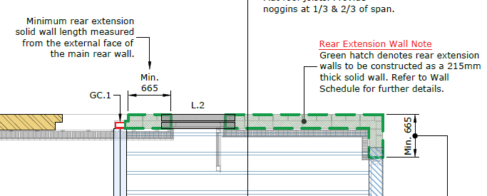
We would like a side door on our extension and our engineer has specified that the wall width between the support column and door opening needs to be 665 min as per the image below, which is causing us some problems and seems excessive to me. I would like a second opinion on this please and if there may be a way to reduce this or a justification for why this dimension is required. Thanks, in advance
-
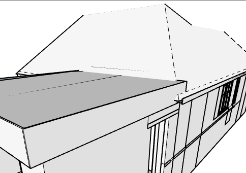
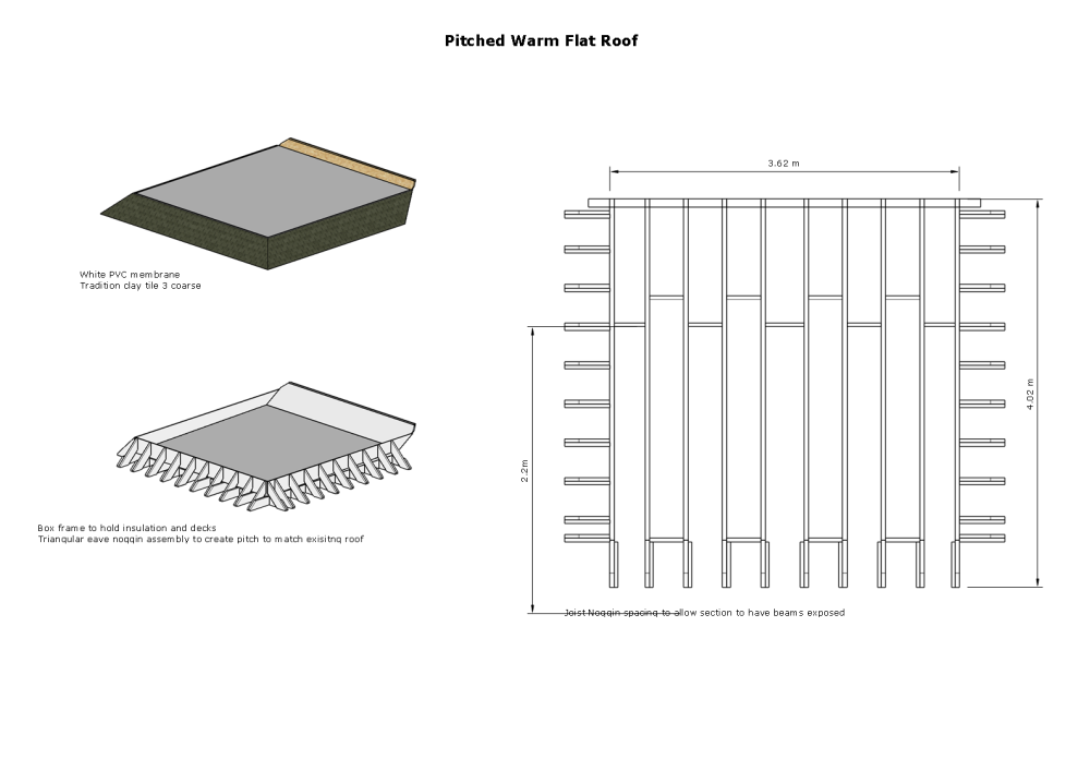
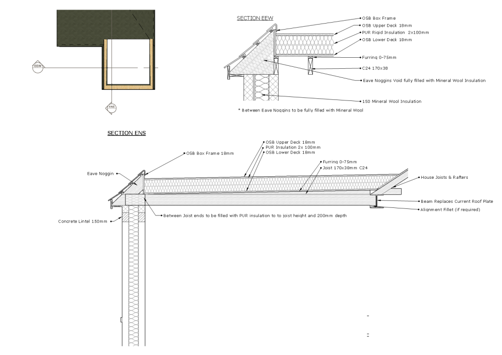
I would like to have a flat warm roof for our new extension but as the our house has a pitched roof am not sure how the abut the too as the exterior walls will be flush and so the large flat roof fascia, deck and insulation will cut awkwardly into the pitch roof and i am not sure it is even possible. So i modeled a flat roof with an eave noggin arrangement to create a pitch all round and would like to some comments from anyone that may have done something similar and if it seems feasible before I get an engineer to review it (See attached drawings) Alternatively if anyone has an example or advice of how the first option; with large fascia cutting in might work, I would be grateful. Also could you advise on how much either option might cost to build ? Thank you
-
We are doing a complete home refurb, including new door and window opening and I had an idea about lining these with a 2x4" treated timber frame into which windows and door can then be fitted. The benefits, I thought, would be 1. Precise opening dimensions avoids discrepancies during construction and window and doors can be confidently ordered when the build starts to avoid delivery delays. 2. Since wood has better thermal performance to brick, this will act as an thermal break between the window frames and brick work. Any thought on why this may be a bad idea please. Thank you
-
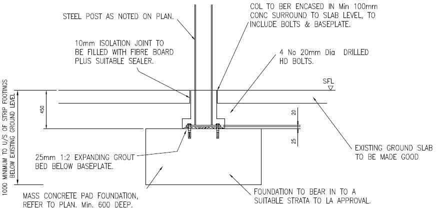
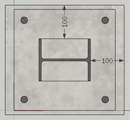
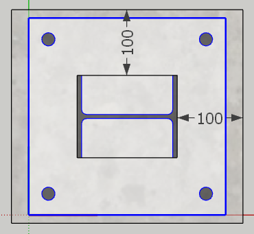
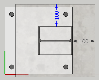
My engineer has stated the following on our drawing "COL TO BER ENCASED IN Min 100mm CONC SURROUND TO SLAB LEVEL, TO INCLUDE BOLTS & BASEPLATE." along with i am trying to understand what is meant by "100mm CONC SURROUND TO SLAB LEVEL" is it that the concrete should project 100mm from every edge of the beam like and in the case of an offset column like The reason for my confusion is that the drawing does not seem to illustrate such a mass around the column and foot , making me thick I am misunderstanding. Thank you