Bruce
-
Posts
37 -
Joined
-
Last visited
Everything posted by Bruce
-
How to attached studwall with cavity with no ceiling connection
Bruce replied to Bruce's topic in Heat Insulation
They are quite assertive that they cannot give tips/tricks or recommend anything really, just confirm or deny design suggestions due to liability reasons. I really think that with a bit of dpc and those sloped brackets that they will be happy so we are goign with that for now. -
How to attached studwall with cavity with no ceiling connection
Bruce replied to Bruce's topic in Heat Insulation
Sorry but I don't understand the question? Are you telling me it has to be SS? The reason I have looked at the one pictured was that I don't see how to use those ties when the brick wall is already in place. But maybe they can be bent and drilled out to work? BCO didn't seem to like the idea of any timber touching the external wall (on the "external" side of the VCL), but yea it looks like the window board is going to have to be part of the stud wall structure/fixture. -
How to attached studwall with cavity with no ceiling connection
Bruce replied to Bruce's topic in Heat Insulation
BCO have clairfied that they expect any wall ties to have sufficient slope towards the external wall or have a drip in them. We intend to use the below type combined with DPC which hopefully gets their approval.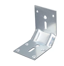
-
How to attached studwall with cavity with no ceiling connection
Bruce replied to Bruce's topic in Heat Insulation
That souunds like a good sollution. I was somehow fixated on using a timber batten as a bracket which aboviusly they where not happy with. Your sollution with a steel bracket I didn't even think of. -
How to attached studwall with cavity with no ceiling connection
Bruce replied to Bruce's topic in Heat Insulation
To avoid leading any pentrating water/moisture that comes through the brick to the timber frame as per BCO demands. -
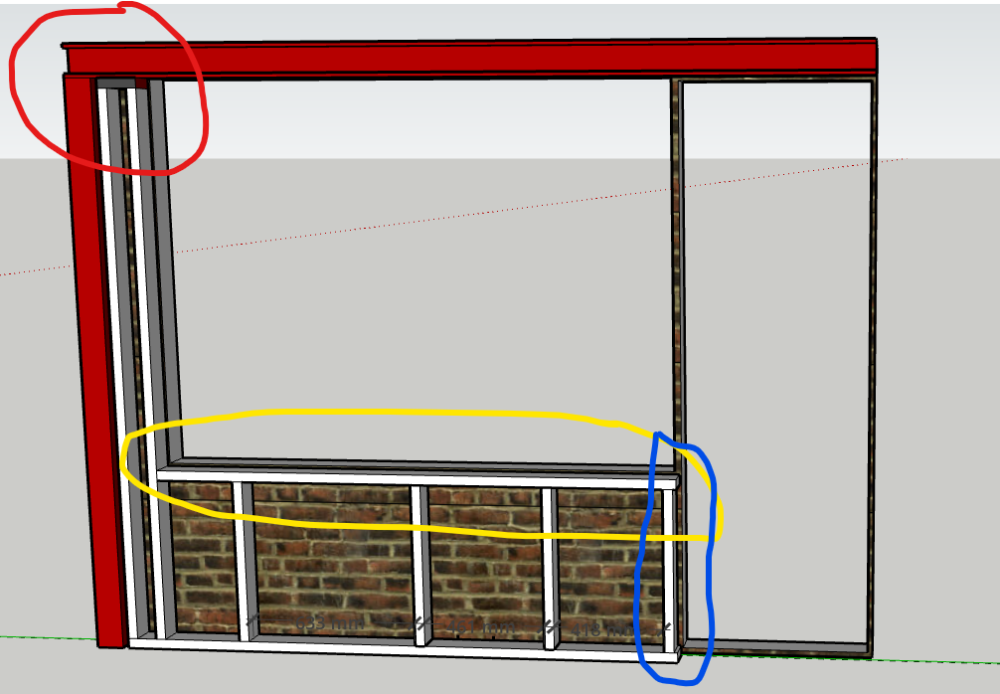
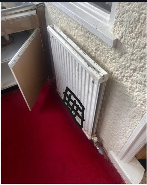
We are currenly insulating and external wall with a timberframe and a cavity to the studwall, the goal is to not to attach the fram to the brick att all if possible. The crux is that the wall is under a window and then it ends at a door so no ceiling nor no side connection. Does anyone have an idea on how to build this without making it super wobly? I guess we need to attach it somehow to the wall but I'm not sure how to do that and make it BC compliant. To the left and above the window we have steel that we can potentiall connect to. Is there any spacers that can do the job or can the window board just do it all? Though that doesn't stop the wall from movin away from the brick wall.
-
Waterproofing window sill with too little incline
Bruce replied to Bruce's topic in Waterproofing & Sealants
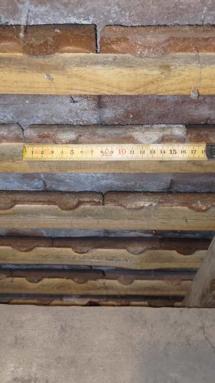
I forgot to take a picture but I measured the slope to about 3°, so definitely on " too flat" side. -
Detail of IWI on single skin / half brick wall for picky building control
Bruce replied to Bruce's topic in Heat Insulation
DPM then 75mm PIR and joists with 18mm floor boards with UFH system on top (22mm). Not really, it would look really awkward with the rest of the external wall on that side. We have submitted to the BCO now with the timber wall solution from Celotex with the following layers + a VCL between the service void and 90mm studs instead of relying on taped PIR joints. What I'm thinking is that perhaps the service void could be turned 90deg (i.e. lying down) to reduce cold bridges and even make it easier for cables as they will run horizontally rather than vertically. I bet there are good reasons not to do it, but it seems reasonable when thinking about the thermal bridges.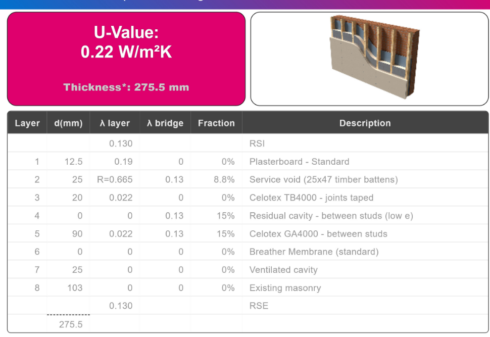
-
Waterproofing window sill with too little incline
Bruce replied to Bruce's topic in Waterproofing & Sealants
Thank, I will take a picture with my smallest level and post it. Not to be lasy but rather asking for experience, do you have a link to the EWIstore that you used? TIA -
Waterproofing window sill with too little incline
Bruce replied to Bruce's topic in Waterproofing & Sealants
It's the tiles that they complain about. -
Waterproofing window sill with too little incline
Bruce replied to Bruce's topic in Waterproofing & Sealants
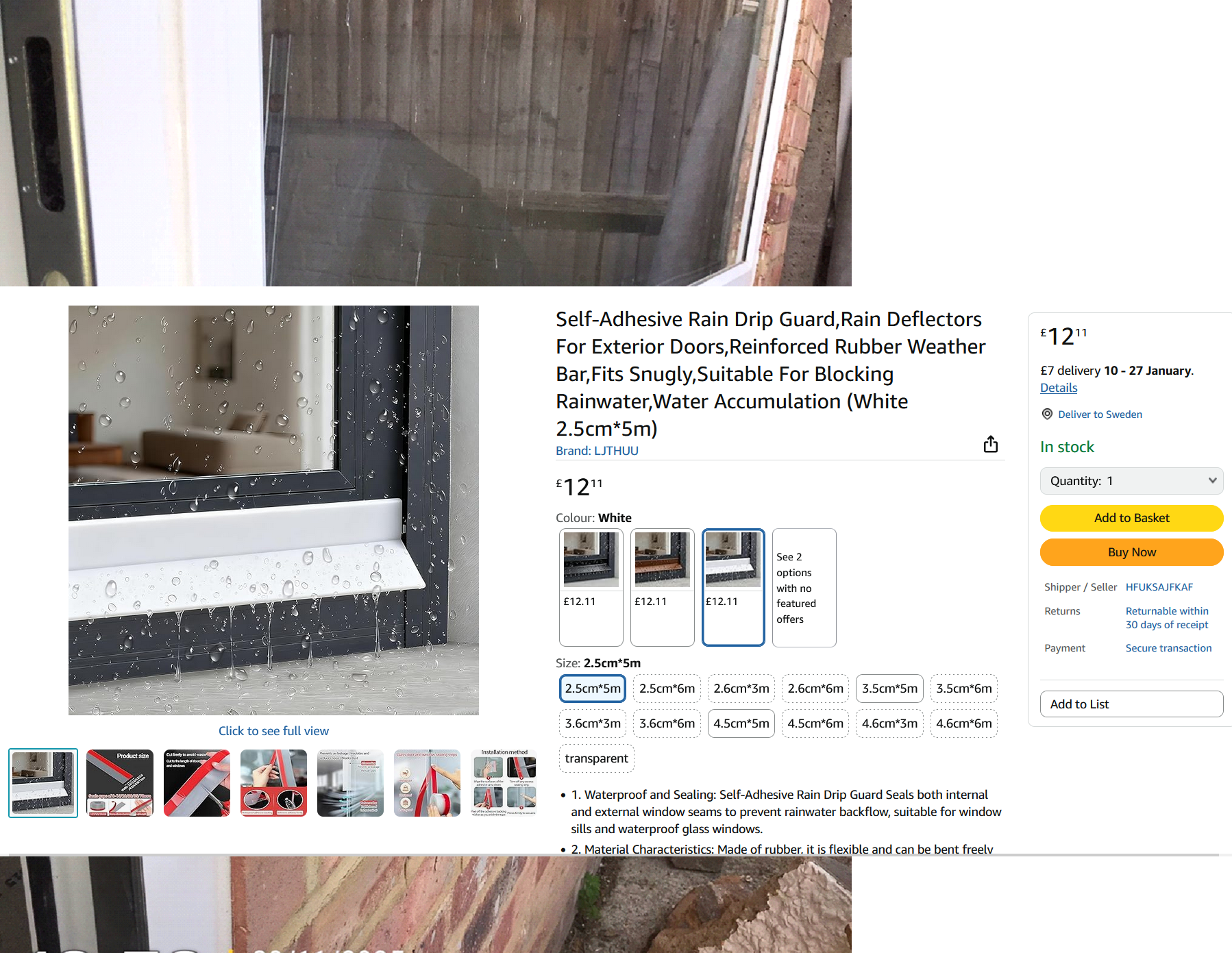
I like the look of that but not sure if it helps with the incline of the sill if just mounted on top of it? -
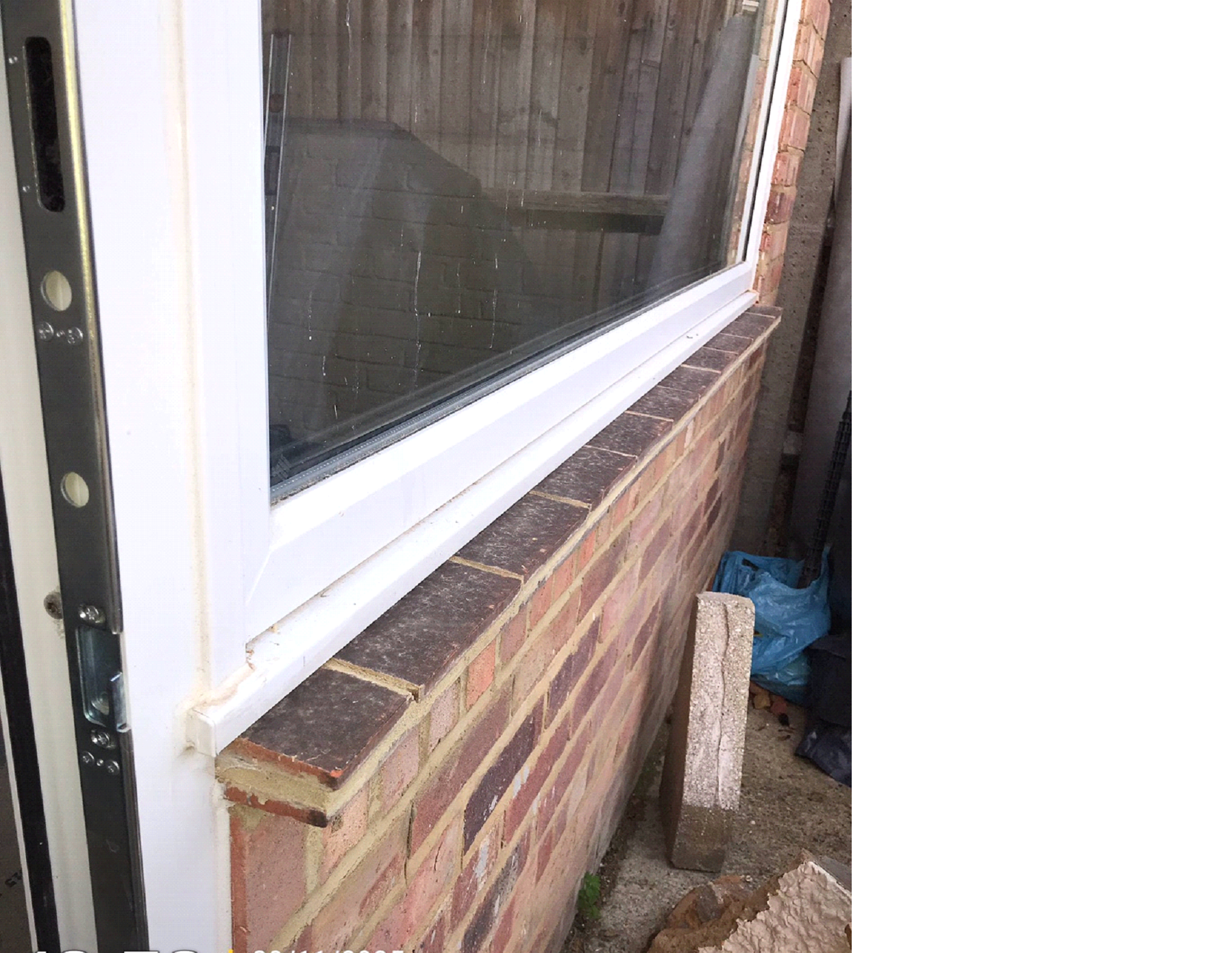
Our BCO is not happy with the incline of our window sill and say it might lead to water ingress. They alluded that the sill should not need redoing but they were not allowed to tell us how. So I'm after any ideas that we can use/submit on how to retrofit a simple solution to this problem. I'm thinking maybe suggesting something like the below pictured diverter but wanted to see if someone else has done something clever before me? We have had this window like this since August, without any selaent under it (life got in the way) and it has never leaked.


-
Detail of IWI on single skin / half brick wall for picky building control
Bruce replied to Bruce's topic in Heat Insulation
Roof is already converted, 170mm Celotex. Windwow is double glazed and door tripple. We are going to suggest as change to the following celotex soolution + another 25mm insulated service void behind the plasterboard which adds a tad more insulation. We are excempt of the u-value due to the limited floor space so don't worry about the non compliant u-value.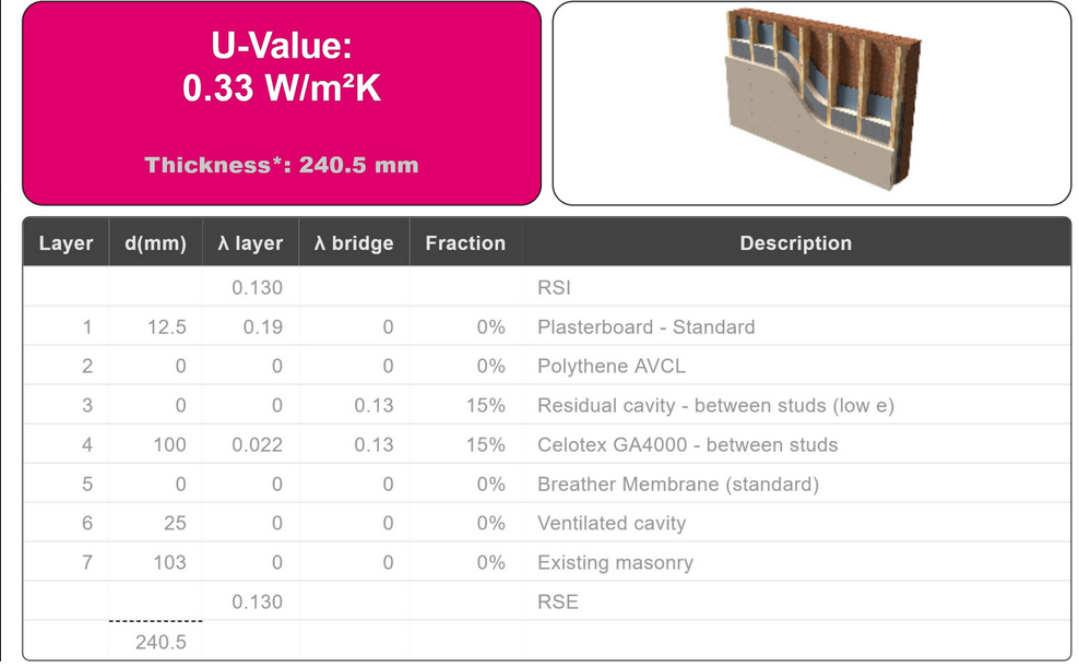
-
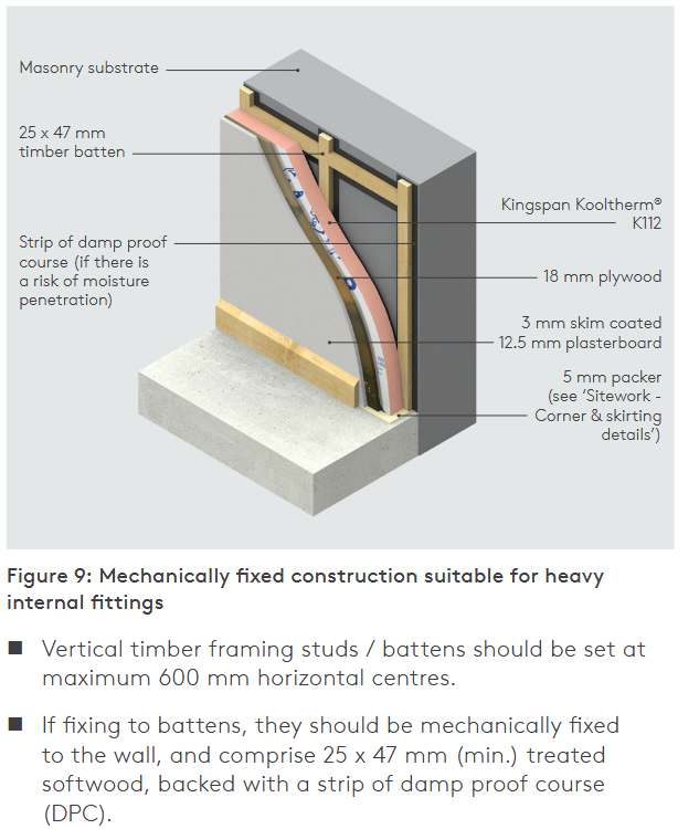
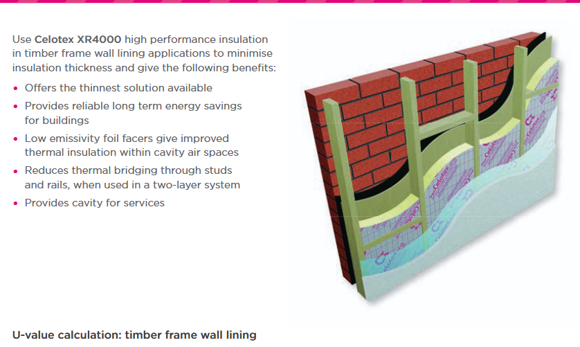
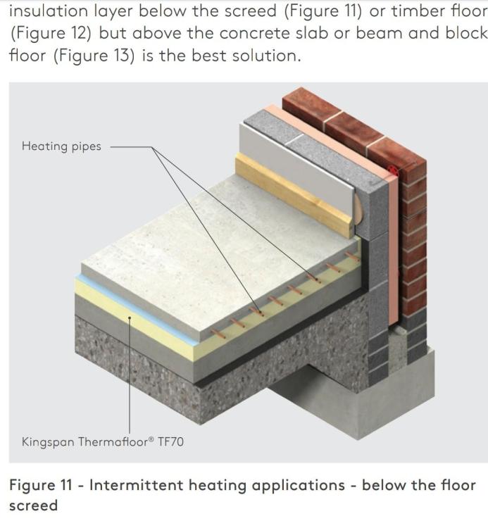
We are insulating our conservatory to bring it into the heated envelope of the house and was going to use the SWIP system but our building control won't approve of it as SWIP have their BBA certification done on a double brick wall rather than just one brick. It is also rather expensive with not great insulating performance but I was prepared to take that hit but I just feel deflated by the retraction of approval from the BC. So I am abandoning the idea of having a vapour open insulation and will go with a more traditional PIR insulated wall. But to make them happy, I need to submit a detail of what we are going to do. What I want is something similar to the one below from Kingspan but I want it to be PIR manufacturer agnostic or from a manufacturer that doesn't charge £350 for two sheets of insulation. I really like how simple it looks. Has anyone done this with Celotex GA4000, how do I do that and make BC happy? Alternatively, we could do the stud system based on below Celotex system (but this one seem outdated and cannot find an updated version). But using a timber stud wall like that, how do you create the distances needed to create the cavity, just blocks on treated timber? Any help appreciated.
-
Joe, we are finally on our way with the garage. Slab poured yesterday and the garage should be delivered in about 4 weeks. Did the Fixall adhesive solve the water ingress issue for you? I'm looking into what ashesive to put under my plast boards and want to it it right from the start. Sounds like you have no succes the with the PU/foam strips.
-
Feels like a very straight forward piece of work, I wonder if I can get away with a onlione SE?
-
We are converting our coservatry to a habitable space, thus adding a insulated roof which the curent wall is not suitable for. So a beam will we added, resting on a brick column on a new pad foundation and a more robust wall in the other end. The new pad is going to the upper right corner on the drawing. The load from the column, roof (as shared between the two ends of the beam) etc. on the pad is estimated to be 7kN +100% margin=14kN. I have calculated the area of the pad to 500x500mm as per Table 10 of Approved Document A. Thickness is assumed to 400mm thick. I would prefere to not have it so deep but I have allowed to the depth to underside of pad to be 1000mm in line with Section 2EA as we have clay soil and I don't know how to show its shrinkability. A concrete column will be made to get up to the concrete floor level where the builder will make a brick column all the way up to the beam. I'm worried to about our building control, I don't seem to speak on the same wavelength as them so I'm trying to be proactive here as they are coming around to look at the hole where the pad is going. Have I done enough to calculate this, how can I prep so I'm prepared to make them happy without having to make bigger foundation than needed?
-
Garden Room - 'substantially non-combustable'
Bruce replied to having a go's topic in Garages & Workshops
I'm would be happy to put up fire rated plasterboard on the inside and steel cladding on the outside on the wall towards the neiboughrs garage but I have a hard time understanding when enough is enough and how much details I need to be carefull about. I want to do it right but it doesn't seem reasonable that I need to pay hundreds of punds to the BCO for their confirmation, especially as they don't offer any advice, the only check what is being submitted. -
Garden Room - 'substantially non-combustable'
Bruce replied to having a go's topic in Garages & Workshops
We are about do the same but with a garage. What was your BCOs response? Ours are being awkward and I don't get any good responses from them. -
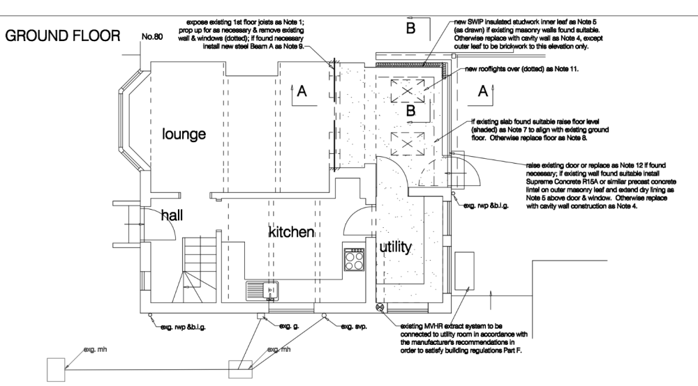
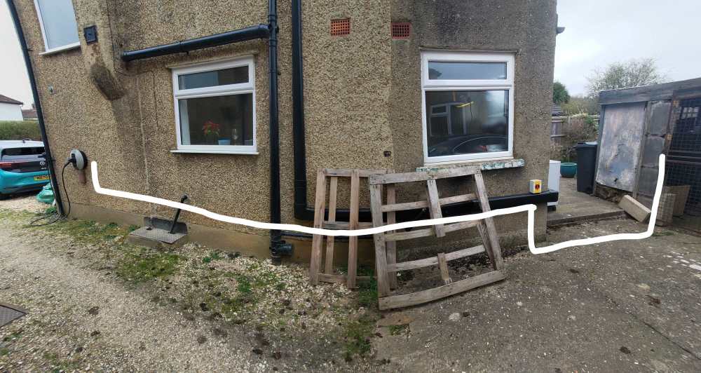
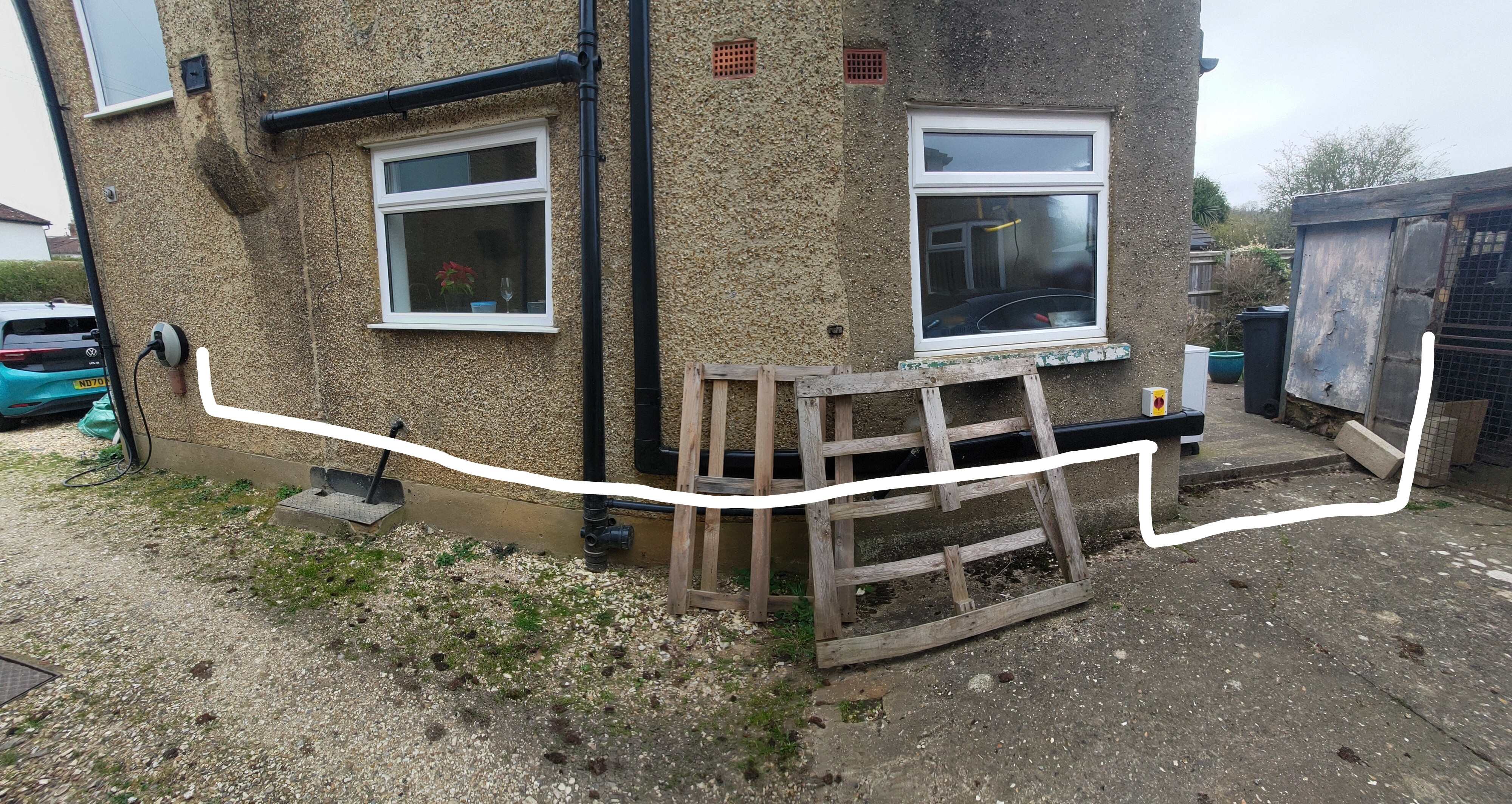
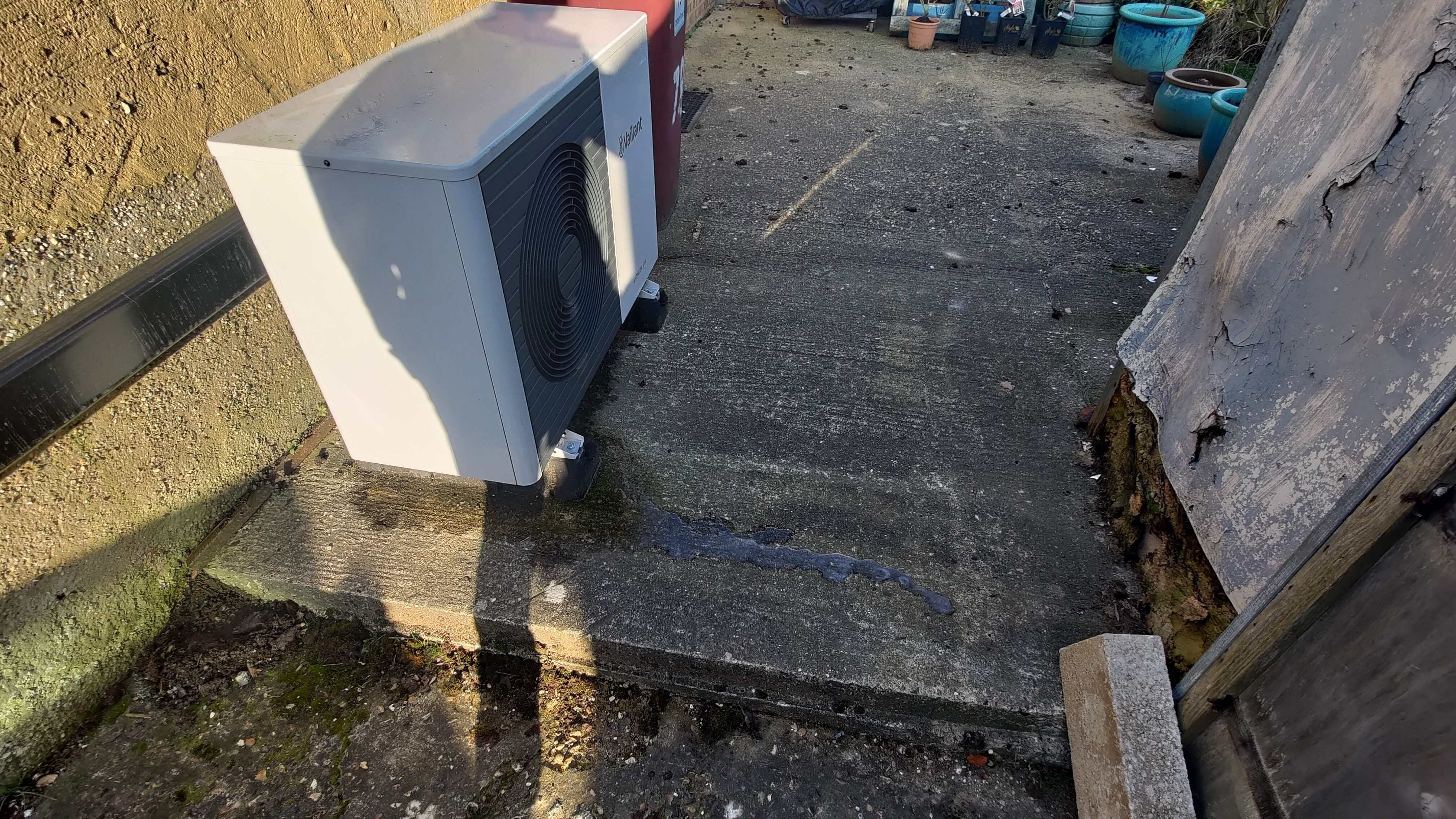
We are preparing a new garage which we need to pull both electric and data cables to, at some point the ducting need to change from what is underground to the ducting the will run outside along the house to meet up with the consumer unit which is inside together with the network connection. I'm thinking that I should bury ducts, perhaps 2x 50mm O.D (intend for 10mm cable for potential PV inverter hense the size) and then teminate them into connection boxes on the house, the other end will terminate inside the new garage so they don't need to be water tight. But twin walled flexible ducts of this size doesn't seem to have glands or the glands cost £30 each which feels redicilous. The length undergrouund is only about 2m so could be done with rigid ducting if there is any that can be burried underground. My two picture below is for the whole length, our consumer unit is behind/indoor of the EV charger and the current carport is in the same location as the new garage, so I'm thinking that the interface between undergorund ducting and the wall conduit is near the ASHP isolator. Does anyone have any idea on how to do this? I feel like this should be done on many projects so I'm a bit suprised to not find a good interface between undeground ducting and rigid ducting/connection boxes.

-
Thank you Joe. After reading this thread once more I think I start to get the difference between the planning and building regs in this matter. I would be delighted to get some help with the design of the slab, even though this might be a spring project as the time just flies away with doing the rest of the house.
-
Joe that looks really nice. Me and my partner are looking at doing a garage in the same style as you but I'm worried about planning as it is is within 1m the boundary, bigger than 15m2(ideally) and made of timber. How did you go about your planning permission? And as I presume you went after PP in the end, how did you design the slab? I would like we already have some concrete hard standing under our carport which it will replace but it is not big enough, even enough or high enough so will likely need to add a slab on top of it.
-
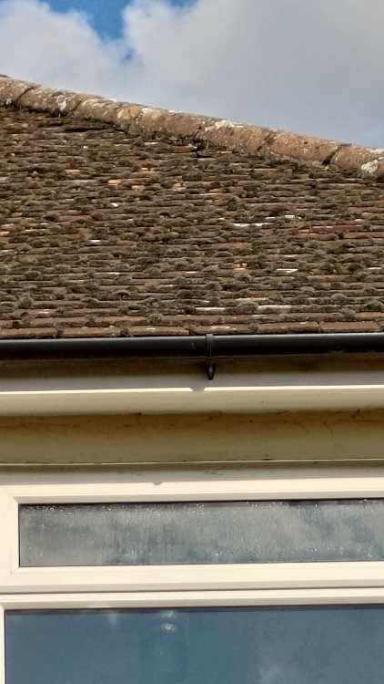
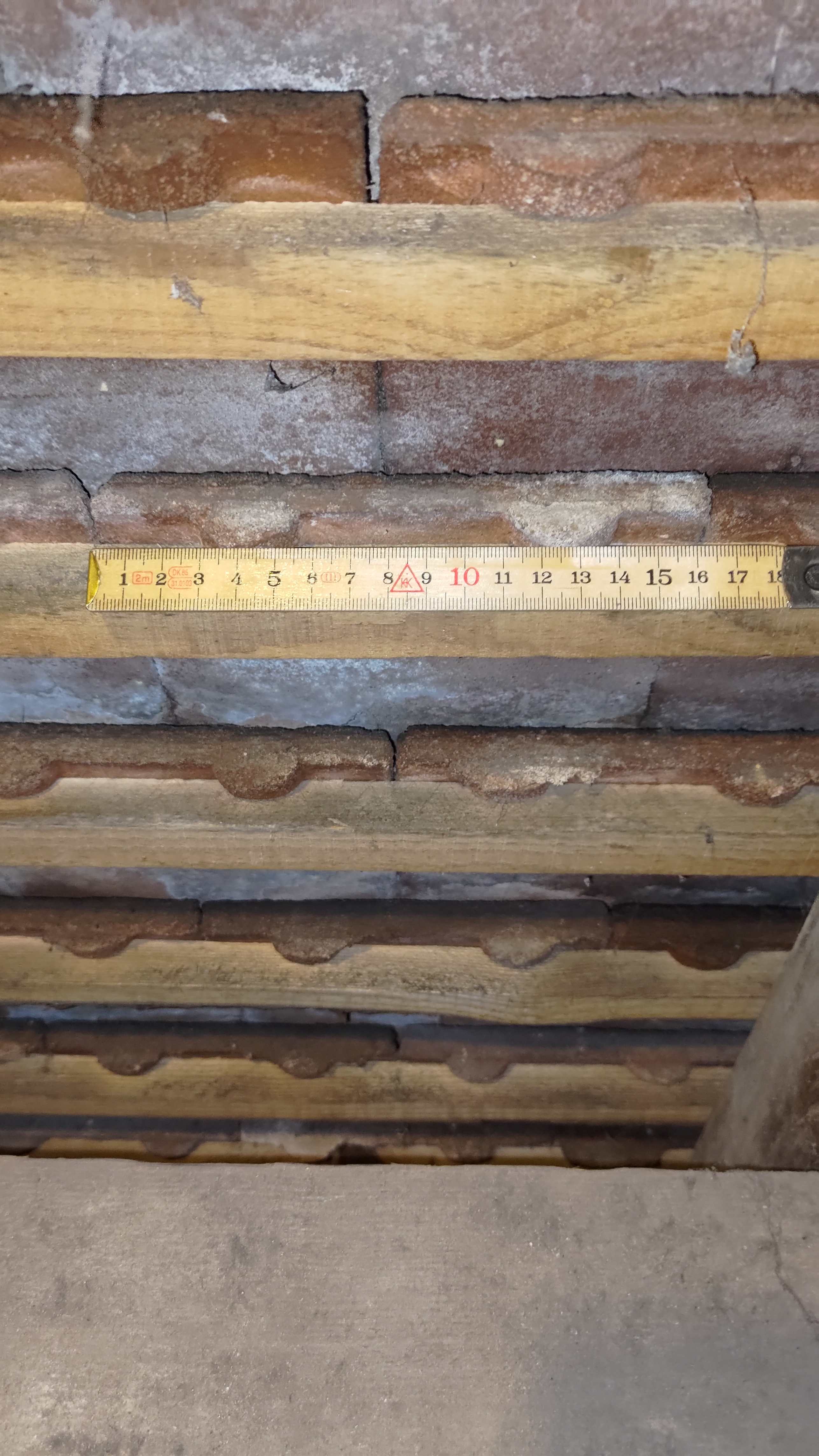
I'm finally about to install the extract and intake ducts/terminals to our MVHR, I have abandoned the idea of venting to the facias as the space between the roof and the top of the external wall is only about 80mm so it will go through the roof instead. We have clay tiles that are about 160mm wide, picture from inside and outside of the roof below (sorry for that bad external picture, it's taken from the ground). Would the Ubbink UB19 work for intake and extract? It looks like it replaces 1+2+3 tiles, is that correct? https://www.roofingsuperstore.co.uk/product/ubbink-ub19-500mm-x-460mm-slate-vent-anthracite.html I would also have to add the 'adaptor' to be able to get the ducts on it + a steep down to our 120mm ducts. https://www.roofingsuperstore.co.uk/product/ubbink-felt-sleeve.html https://www.roofingsuperstore.co.uk/product/ubbink-stepped-adaptor-1.html Can anyone spot anything wrong with my assumptions/ plans?
-
That is a fair assessment but the amount of work with ripping out the old pad, the subbase under it and the pour a new pad is a lot more work than doing what I describe above and also much more costly, I'm not sure that the extra insulation added will ever be worth the investment. What it would likely enable though is a presumably easier routing the extension for the airing bricks, that solution is really what I would love some help/examples with.
-
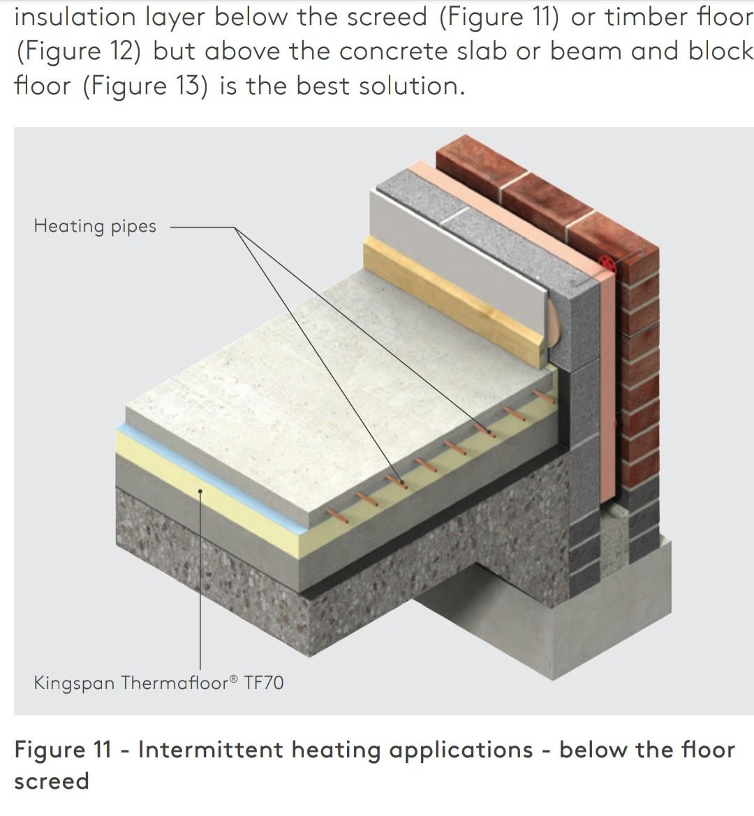
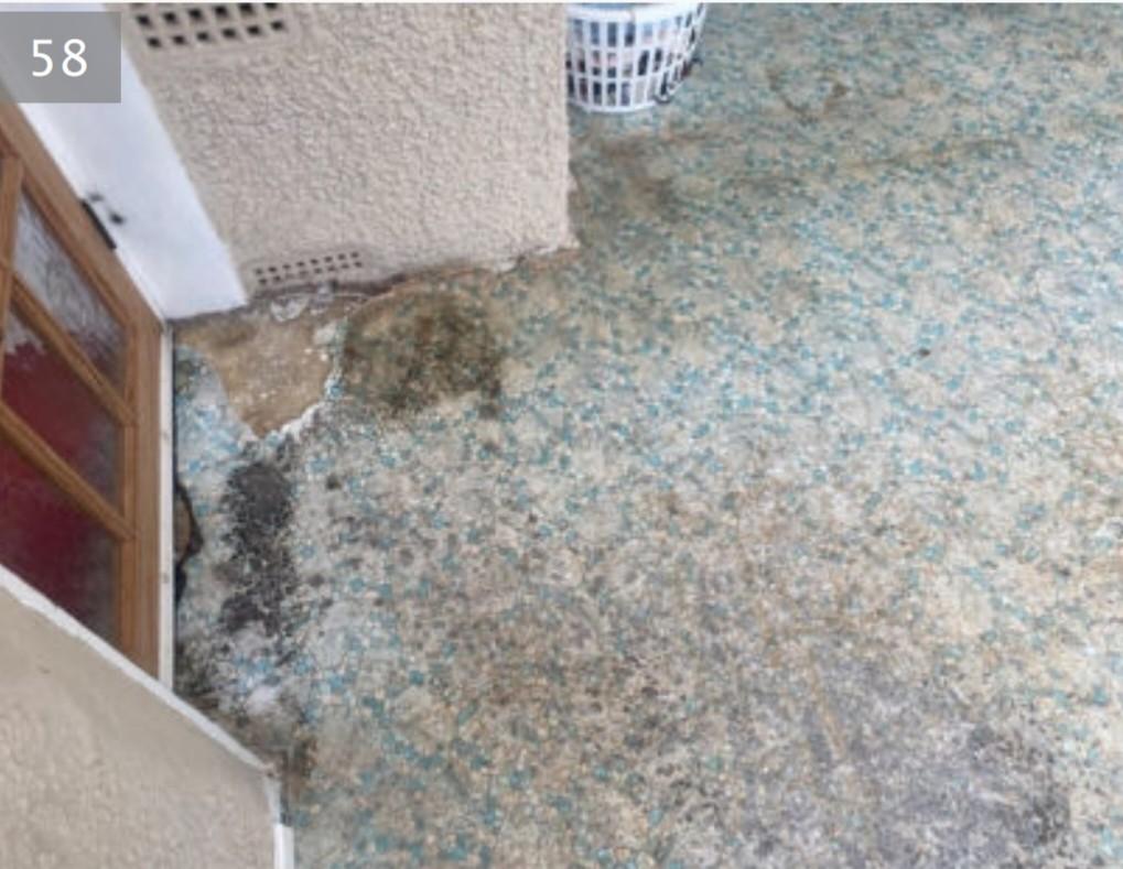
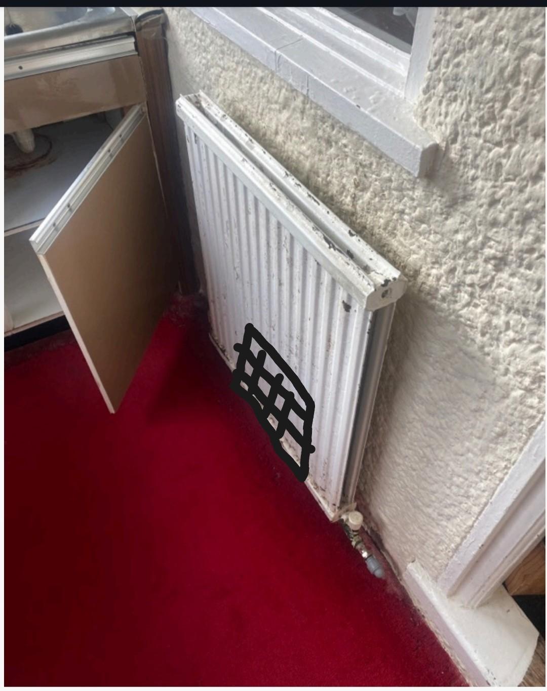
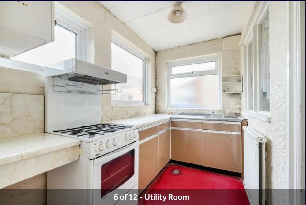
We are planning on insulating an levelling the floor in our extension which was made in the 60s. The floor is concrete with tiles on top. We are planning on putting down a DPM then 100mm Kingspan Thermafloor TF70 with another layer of vapour barrier and then lay 16mm UFH pipes and 32mm liquid screed which should leave us with 13mm to lay tiles on top for the utility room. Total thickness we need to achieve to be level with the suspended floor in the next room is 145mm. The suspended floor in the next room is the where it gets a bit tricky. The airing bricks are just open into the extension and will presumably need to extended. So the question is, how do we do that with the least need to breaking up the old slab, or perhaps we don't need to do that at all somehow? And then, how do we connect the extension so the external walls in a good way? Attached are a couple of pictures of our utility room and our lean to/ conservatory, the floorplan with red drawings on how I think the 3 air bricks needs be extended, and the technical drawing from Kingspan that I think suit our situation. Any thoughts on how can do this?
_1.thumb.jpg.105b1f58b610e7f16fdd39c337f4f481.jpg)


_1.jpg.b7f041c6f7ffe63fd088b8bc860cc782.jpg)