


MattD
-
Posts
14 -
Joined
-
Last visited
MattD's Achievements
Member (3/5)
0
Reputation
-
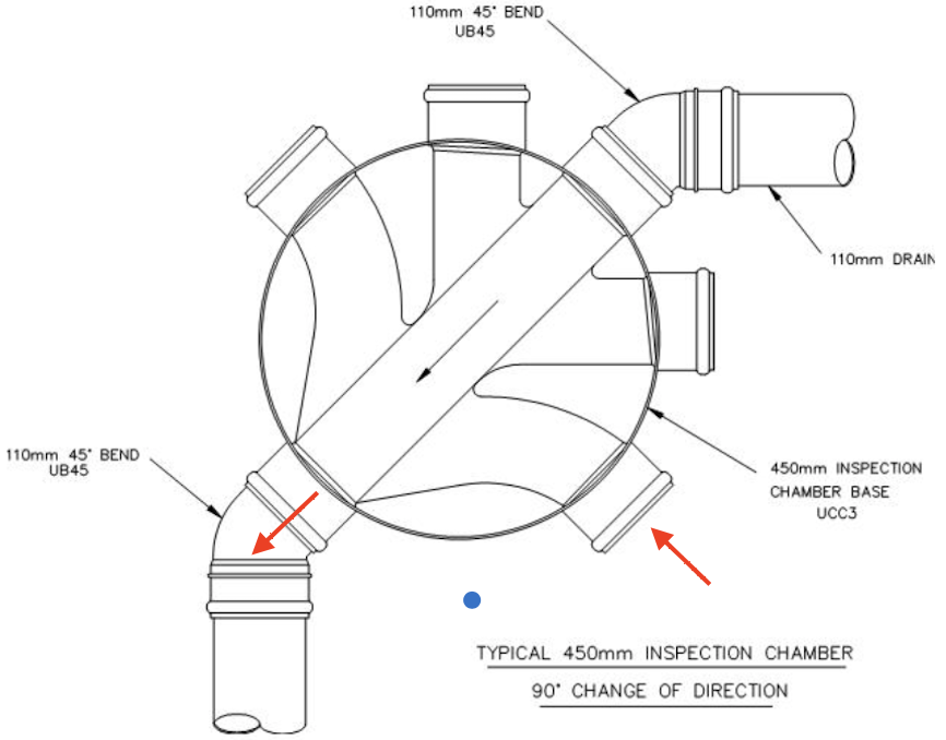
Thanks @ETC. But why does that matter? I guess it has to do with efficiency of the flow and/or reducing the risk of the IC silting up? But if all of the inlets were in use then wouldn't two of them have to bend by 90° anyway..?
-
I understand that the 'correct' way to turn a drain through 90° at an inspection chamber (IC) is to connect a 45° elbow at either end of the IC. The diagram below comes from here (I have added the red arrows): As a total newcomer to the field, I'm struggling to understand why the preferred method isn't to simply connect the incoming pipe into the inlet which already enters at 90° to the outlet, i.e following the red arrows. That would avoid the need for the two additional 45° elbows, and presumably would make rodding easier too. I must be missing something. Can anyone explain why the above is preferred?
-
Minimum distance between foundations and drains/services?
MattD replied to MattD's topic in Foundations
Thanks @Conor. Actually that sounds very sensible! -
We are due to begin put drains and services in for a project soon but are yet to finalise the foundation details with the structural engineer. The services will be running alongside the outside of the buildings. One building will have spot foundations, and the other strip founations. Since we don't yet know how deep our foundations will be, I can't say for sure whether the drains/service trenches will be higher or lower than the bottom of the foundations. What is a minimum distance from foundations for service trenches to run where the foundation depth is not yet known? I'd rather put them a bit further away from the buildings to avoid future problems, but we're on a slope and putting them too far from the building would also lead to excessive groundworks so am looking for a sensible but safe distance. Of course the inspection chambers will come a little closer than the drains themselves, so there may be different distances for (1) drains, (2) inspections chambers and (3) other services (water pipes, cable ducts etc). I'm assuming that there is no minimum distance for (3), but their inspection chambers may need to be a certain distance?
-
Thanks @nod. That means that I can rule out buying off-the-shelf – one way or another, it seems that making use of this glazing would be the right thing to do. So what I need to work out is whether to build myself or get someone else to do it. Our windows really do need to be wood framed (not just wood effect uPVC) as our build is required to have an ultra-low ecological footprint. Reusing existing glazing is another plus point in that regard. Any thoughts anyone might have on the pros/cons of building ourselves (given a modest workshop and an 'inexperienced but willing to learn' attitude) would be appreciated. Any idea of the relative cost would be helpful too (in terms of materials only for self-build vs materials and labour for purchasing in). I also have no idea by how much providing our own glazing will reduce the cost. Clearly that limits us to local carpenters since they will need to collect the glazing from us first.
-
I'm designing a new build to the latest regs. A neighbour recently had new glazing fitted to their entire house and the company that supplied them mis-measured everything by ~5mm (they were fitting new glazing in existing frames). The company turned up with the incorrect sized glass and they got to keep it. They have offered me all of the incorrectly sized glazing (Pilkington K) for free. Many of these donated glazing units would be quite close to what we need, so I'm minded to take up this offer and get custom-made window frames to fit the glass. There will be a slight deviation from original window sizes, but we need to put in a planning amendment to adjust other aspects of the windows so this is all changeable. We're required to use wooden window frames. The way I see it, I have three options: Self-build the window frames to fit the glass Commision custom-made window frames to fit the glass Ignore this offer and just buy off-the-shelf windows in standard sizes I read here that the price of off-the-shelf windows is now roughly the same as custom-made windows. Assuming that's true(?), then it would make sense to make use of this glass, as presumably it will bring the build cost down. I appreciate that the major part of a window cost is the frame, but I presume this would at least make enough of a difference to be worthwhile. That leads me to my main question: should I build window frames myself? By the time we come to build the house, we will already have built a workshop. I'm not a carpenter, and I realise anything I build will not be to the same standard as someone who does this every day. However I'm not in a rush and am able to do a reasonable job at most things given enough time, reading up ahead and the right tools. Our workshop will be kitted out with handheld powertools, but no specialist heavy bench-style stuff (pillar drills etc, although I may be able to justify getting something if it is likely to be useful in future). I think the main factors to consider are: Certification requirements (CE marking?) etc – if this requires external certification it may just not be worth doing myself Not worth doing if I need complex machinery which we can't justify buying just for this project Cost in terms of my time versus just paying a skilled local carpenter to do it – I will obviously be slower. Of course the satisfaction of having built my own windows would be a plus, but not if they leak! Any experiences others have had would be welcome. I realise it's not a straightforward answer and depends on several factors.
-
We're in Wales, meaning all new builds must have a sprinkler system. We're designing a two-bed timber framed cottage with one-and-a-half floors (bedrooms in the attic space). Sprinklers are required in bedrooms, meaning we will need to allow for the sprinkler pipes in the ceiling service void. Since the bedrooms are in the attic (roof space), service void space is limited. I was under the impression that a ceiling service void is typically 25-75mm: 25 if you only plan on running cables, and 50 or even 75 if you plan on running water pipes too. Just to be on the safe side, I thought I'd contact the sprinkler company we're thinking of using to ask them how much space they need. They said 120mm (as a minimum!) Does this sound right? Can anyone else who has built for a domestic sprinkler system confirm if this much space is really necessary? If we make our ceiling service void that large we would effectively need to box in the entire timber frame, which would be a real shame. I'm not entirely convinced that the sprinkler company really understood what I was asking about, but thought it worth asking here in case anyone else has had experience with this. They said the sprinkler heads require 120mm.
-
Is it possible to expose ceiling beams while meeting fire regulations?
MattD replied to MattD's topic in Floor Structures
Thanks all – that looks great @Temp. In our case I don't think I can justify purely decorative beams, and 'beefing up' the actual joists would mean doubling their width which isn't economical. The house we're building is a traditional timber frame anyway, so that will all be exposed (and is chunky enough to do so). Given the requirement for noise reduction, fireproofing etc (not to mention that this complicates fitting of sprinklers as required in Wales), we will just box them in! -
Is it possible to expose ceiling beams while meeting fire regulations?
MattD replied to MattD's topic in Floor Structures
Thanks – hadn't thought to consider sound transmission yet; that might cinch it. ...So your oak beams are purely decorative? -
Is it possible to expose ceiling beams while meeting fire regulations?
MattD replied to MattD's topic in Floor Structures
Thanks all. We are of course free to spec the floor joists as we see fit. From my reading online, it looks as though we just need to know the charring rate for the material (softwood), which gives the amount of material that would be lost from each exposed face, per minute, for the required duration. I see varying figures online – can anyone point to an authoritative source that Building Control would refer to when making this calculation? For example, if the charring rate is 0.8mm/min then for 30 min resistance that's 0.8*30 = 24mm of sacrificial timber required for each exposed face. But if the figure is 0.65mm/min, it's only 19.5mm. I assume that you then just need to check against span tables that the reduced member size is sufficient for whatever it's supporting. Can anyone confirm if my understanding of the calculation method is correct? Also, thanks for the tip on intumescent varnish. Are there 'accepted' figures for how much time these varnishes gain you on the above calculation? -
I'm designing a new build dwelling. I understand that Building Regs (part B) makes it difficult to have exposed beams in ceilings (i.e. exposing the joists of the floor above) due to the need to have 30 minutes' fire resistance. But is it absolutely impossible to meet the regs with exposed timber beams? I think this is sometimes also referred to as 'ceiling pockets'. How do you estimate whether or not a particular design (material + thickness) has 30 mins fire resistance? I assume the final calculation would need to be done by a structural engineer, but is there a way to get a rough estimate of whether or not something will pass before we send it off to the SE? Furthermore, we are in Wales and this requires us to have a sprinkler system, including a sprinkler in EVERY ceiling pocket, unless the "ceiling pockets are constructed of materials conforming to BS EN 13501-1:2018, Class A1, A2-s3, d2 and B-s3, d2." Does anyone know where to determine whether a particular type of timber falls into one of these classes? This website gives some clues, but doesn't actually provide guidance on what materials would meet the standards.
-
Thanks all. Spoke to BC who confirmed that the 600mm mentioned in the regs is just guidance and 300mm ought to be sufficient when away from buildings and vehicle traffic. In other words anything less than 600mm is taken on a case-by-case basis, but in an uncomplicated case, 300mm is fine.
-
Thanks Joe; was this encased in concrete? Everything I'm reading (other than on this forum, e.g. Building Regs and this guide ) points to 600mm being the minimum cover where concrete isn't involved... Would definitely appreciate if someone can clarify where this discrepancy comes from as 300mm would be a lot easier to achieve!
-
Hi, just reviving this thread in order to understand the other half of the question (i.e. what is the actual minimum depth of foul drainage, where there are no nearby buildings) – @Alan Ambrose mentioned having seen references to 300mm to the top of the pipe – presumably that means without any kind of covering. The Building Regs (H1) seem a little unclear on this – §2.44 says: Table 10 gives the "Limits of cover" of a thermoplastic pipe as being 0.6-7m. So that would indicate that 600mm (not 300mm) cover is required above all foul drainage. However, I'm unsure what is meant by "where necessary" above – does this mean that it is necessary to protect sections of the pipe where the minimum cover is not met, or should "where necessary" be interpreted as meaning there is flexibility in this, depending on the whims of the Building Inspector? I also note that §2.44 uses the word 'recommended cover', whereas Table 10 says 'Limits of cover'. The former suggests room for interpretation, whereas the latter does not. In short, I'm trying to work out if it is always necessary to bury foul drainage by ≥600mm, where no reinforced concrete cover is used.