Solarexploits
-
Posts
75 -
Joined
-
Last visited
Everything posted by Solarexploits
-
Improving output from existing MCS 4kW array
Solarexploits replied to Solarexploits's topic in Photovoltaics (PV)
Ha Ha! I meant 4 miles per kW! -
Improving output from existing MCS 4kW array
Solarexploits replied to Solarexploits's topic in Photovoltaics (PV)
Ok, next daft question, could I add solar optimisers to each panel (DIY?)? Are these "panel specific" or can I buy, say, a 300w optimiser to use with a 235W panel (I think my original figure of 230W was in fact incorrect!) Does this then mean I can keep the Sunny Boy inverter, or do the optimisers need to "talk" to an "intelligent" inverter to work correctly Bear in mind, I'm not looking for absolute max efficiency here, just something that might be economically viable -
Improving output from existing MCS 4kW array
Solarexploits replied to Solarexploits's topic in Photovoltaics (PV)
Just had a look at PVGIS - not sure I'm doing it right, location is Thundersley, Essex, I have kWh at 3.91 & azimuth at -60 (I believe correct for 10 degrees off due West, that's a slight guess), roof slope at 35 degrees, again, a bit of a guess it suggest an output of over 3,600kWh, that would be an increase of over 20%, if I could even get a 10% improvement then that would be worth around £150 a year in FIT payments to say nothing of further reduced leccy bills & also a reduction in gas usage as it improve output to the immersion However, £150 a tear doesn't sound worth stripping panels off the roof & replacing the inverter! I'd hoped the smart controllers could be connected direct from the panels & mounted underneath them, without removal, also hadn't considered it would require replacement of the inverter. Why does inverter need to be replaced? I'd assumed it would simply "see" a slightly increased input coming to it, I take it that's not the case? Re cars & mileage, I already have a fully electric Kona - great piece of kit, 300 mile range in Summer, more like 220 or so in Winter. averages around 4kW per mile, more round town, less on motorways -
Octopus Smart Meter Display suddenly showing export rate
Solarexploits replied to NSS's topic in Photovoltaics (PV)
I've been on Octopus Go since last October, our display has always shown an amount exporting whenever there is surplus, it rarely shows zero, which presumably is just a fluke when incoming & outgoing happen to balance -
I have a 4kW (17 x 230W panels so actually 3910W) MCS array, installed back in 2011, so long ago paid for itself with the FIT payments, the inverter is a Sunny Boy, never had any problems or faults with the system since installation. The array is almost due W facing, very slightly SW/W & is shaded by trees for part of the day, part of the array, particularly early to mid morning & late afternoon/early evening, depending on time of year, substantially worse in Winter than Summer. It produces, typically, around 2,900kWh a year, consistent for last 3 years, since some trees were removed which reduced shading, can't remove any further trees/shading due to TPO's on the tress I'd like to improve the output if possible; obviously this was installed back when no one was installing micro inverters or any form of individual control, the company that installed is long gone into liquidation, they told me it was installed as 2 parts, presumably in parallel to reduce the effect of the shading, though I've never actually checked this by confirming how panels are connected I have zero knowledge of the more modern methods which I believe have more control over individual panels which I understand improves output Can someone please enlighten me on any possible improvements (I already use a Solic immersion controller which is giving me free hot water around 7 or 8 months & reducing gas usage for some of the other 4 or 5). I assume by recognising a single shaded panel & "removing" it from the array improves the performance of any series connected string? What systems are out there, at what sort of cost & how much grief & aggravation to install? Any info most welcome, thanks in advance
-
Solar PV & battery installation on the cheap!
Solarexploits replied to Solarexploits's topic in Photovoltaics (PV)
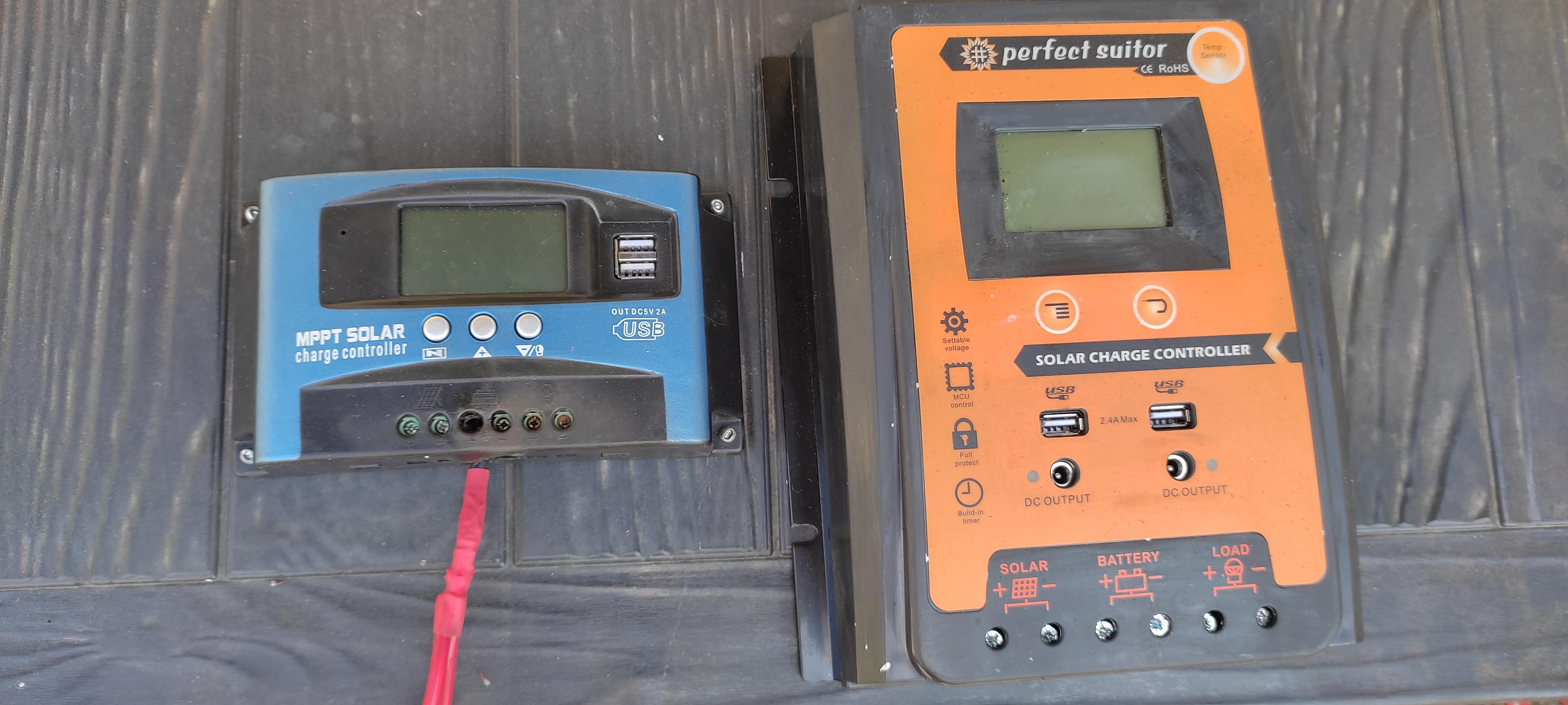
Brief update I checked internal resistance of each battery, there were significant differences & I paired them up to try to create 2 balanced 12V "packs" of 340Ah each. They've been running without problem for the last month & today I checked the voltage of each pair, 12.45V & 12.40V, so almost perfectly balanced Some further info for anyone else looking to do things more cheaply than perhaps the traditional routes. The cheapy solar controllers on Ebay & Amazon are a joke, I fried the "giant of sun" with 4 panels connected to it, the sun came out, who could have predicted that in the UK!!!??? They are sold as 100A, but just looking at the size of the connections & looking at the size of internal components it's pretty obvious they couldn't be more than about 30A, probably 20A at a safe bet. The MCU unit, which is slightly more heavily built than the giant of sun has survived, but only after I stripped it out & made a soldered connection for the main +ve battery input after the screw in terminal connection melted off the main board & almost burnt the unit out!!! I caught it by pure fluke, with the new soldered connection & with some additional heat sinking I've added it's been behaving itself running 4 panels in parallel of 310W each, 2 are roughly E facing & 2 SW so they will never give max output at same time of day, I was more interested in lengthening the charge time rather than max output I've now purchased another. much chunkier & more sturdy controller, another super brand name - perfect suitor, this purports to be 70A & I'd be inclined to believe it, more than double the size of the MCU unit (see pic) & weighing 1.2Kg against less than 400g, for £70 looks like a good buy. I now have 6 X S facing panels connected to this which it is handling without even getting warm, it has a decent proper heatsink on the back too for when demand/amps are higher & the sun is out properly. It also gives a lot more info on the display, PV in, A in, battery V, load A & battery temp (tho' no idea where it would be getting that from is it simply measuring ambient temp?) Bit of further info, the Gobor 3000W (purportedly!) inverter, I forgot exactly which sockets it was powering & let the missus plug the lawnmower in to the outside socket which was on the same circuit - it immediately killed the unit - overload protection, I thought, as I'd tried connecting a little over 2kW previously & had it give up at that point, I therefore expected to switch off & back on for a reboot - however it was completely dead, on inspection the incoming battery power at 24V is protected by 4 x 20A fuses, (it had blown all 4)2 in parallel on the +ve & 2 on the -ve, so 80A total load which I make 1920W total, how they can label it as 3kW & in the instructions state 6kW instantaneous is utterly beyond me, fortunately I was well aware I was buying at the Mickey Mouse end of the market & never have more than about a 1.2kW load on it & that would be fairly rare & only relatively temporary, 1/2 hour to an hour; typical load on it is only around 200 - 300W, under these circumstances it works fine! I can only assume that the lawnmower, although only supposed to be 2kW is actually pulling a lot more than that, a 2kW fan heater simply put it into overload protection rather than blowing fuses. I now have a 7A fuse on the 240V output, so that should blow first to save stripping the unit to change 4 fuses in future! I guess all of the above goes to show, that, to a certain extent you get what you pay for, however, looking at the savings I'm making I reckon the installation will have paid for itself within 2 years, which seems like a good return on investment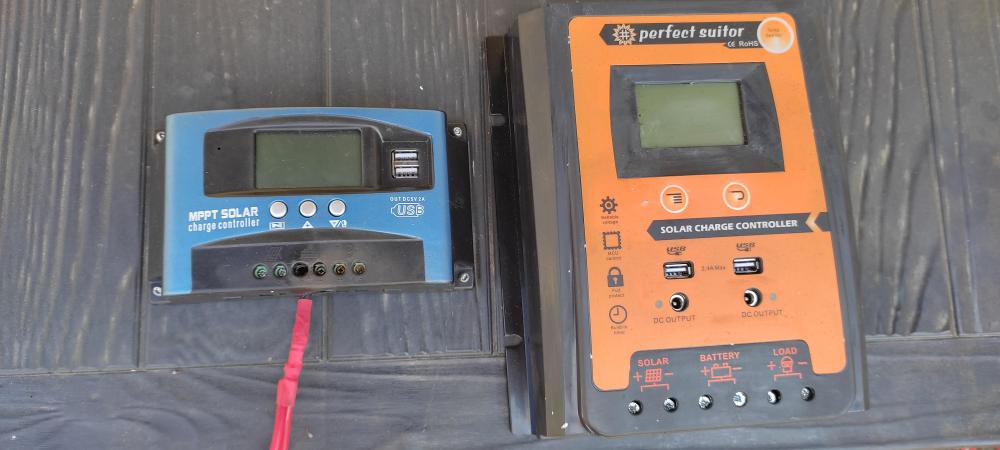
-
Solar PV & battery installation on the cheap!
Solarexploits replied to Solarexploits's topic in Photovoltaics (PV)
So, judging by what's happened so far, I would expect to find the two batteries that were down at 10.5V have a higher internal resistance than the other pair? If I find that to be the case then if I put 2 of the 4 in series which have the closest resistance to the other 2, if you follow me - I've not explained that very well, the idea being to get 2 x 24V units which have similar internal resistance to one another (as 24V "units2), those 2 24V "units" should then charge relatively evenly, tho' presumably I may find they "drift" away from one another over a period of a few days/weeks, in which case recharging the lower charged pair separately would then rebalance things? -
Solar PV & battery installation on the cheap!
Solarexploits replied to Solarexploits's topic in Photovoltaics (PV)
Ok, I'm an idiot! I've found recently I'm not getting the power from the batteries I'd expect, so this morning checked the installation & the individual battery voltages. Turns out that the updated drawing I've done is, in fact, correct. I have each pair of batteries wired in parallel, so 12V @340Ah & then I've connected the two pairs in series, so 24V @340Ah. The voltages between the pairs varied hugely, one pair was down at alittle over 10V, the others up at over 12V, despite them having been on charge overnight at 24V as a pack So, as the 2 pairs are effectively part of the same 24V battery, I had assumed they would all charge at the same rate, that clearly isn't the case. Does this mean I have one pair of knackered batteries (seems unlikely they are 2021 proper solar units, albeit being lead acid), or is it simply that they have different internal resistance & the charge therefore always favours one pair? If I reconnect so I have each pair in series, 24V @ 170Ah & then connect them in parallel, so 24V @ 340Ah, is that going to fix the problem (assuming batteries are sound) & would it be better to mix the unblanced pairs so I have one of the units which currently have the low voltage in each pair I now have the low charge pair charging at 12V to bring the whole pack back up to correct voltage -
Solar PV & battery installation on the cheap!
Solarexploits replied to Solarexploits's topic in Photovoltaics (PV)
Just realised that even the updated drawing is a little wrong! In fact I have the 2 x 12V batteries connected in series, so I have, effectively, 2 x 24V batteries, these 2 "units" are then connected in parallel, so I don't actually have the issues with potential unbalanced charging as has been suggested. I've added another couple of panels in parallel to the array that had just 2, so I now have 2 banks of 4 in parallel with one another (max 2480W) & I've added further circuit to the inverter RCD which should draw rather more off overnight - TV & most other low draw power circuits. I've still kept the large draw stuff like cooker, microwave, kettle & garage stuff etc on the grid along with the fridge/freezers, we'll see how that goes! -
Is eBay a good idea for a novice?
Solarexploits replied to CotswoldDoItUpper's topic in Photovoltaics (PV)
I've gone for cheap Chinese stuff to try it out, if it goes up in smoke, I can easily switch circuits back to the grid temporarily, so far it's all behaved itself. I have a dirt cheap "Giant of Sun" controller, which purports to be MPPT & PMW, but I strongly suspect it is in fact only PMW, hence I bought a dearer MCU unit which is MPPT, both actually seem to work well, I run them in parallel with each other. The inverter is again a cheapy, Gobor 3kW unit (6kW peak), but I'm rarely drawing more than a few hundred watts from it, wouldn't want to draw kW as it's only 24V & the current would be pretty hefty I haven't really attempted to "match" anything, I mean, I've made some calcs, but the variations are huge, so it's largely suck it & see, today I've added some more circuiots from the comsumer unit to the inverter fed RCD Tp explain I already have an MCS installed grid tied 4kW array which went in right back at the early tariffs & that also runs a Solic immersion controller which diverts excess power to the immersion heater instead of sending it back to the grid, I'm getting free hot water around 8 months of the year & a reduction in gas usage all year round from this. The idea with adding further panels was to remove some of the base draw circuits from the main house, thus freeing more of the 4kW array power for heating hot water & covering the main household demands for large draws such as cooker, kettle & the EV charging point, as I'm on a dual tariff for the electric car I get 4 hours of overnight leccy for 5p a unit, so I have a large Rohr battery charger to top the batteries up overnight, set on a timer. I still have only 8 of the 10 panels I purchased connected so far, but I'm finding that on sunny days like we've had recently, the smart meter is showing that I'm sending a little back to the grid & getting hot water for free What vehicle do you have for V2G, I have a HYunddai Kona & so far as I'm aware that won't do V2G? -
Is eBay a good idea for a novice?
Solarexploits replied to CotswoldDoItUpper's topic in Photovoltaics (PV)
Yeah, lead acid, I'd love to have bought lLi within that price bracket! 😁 -
Is eBay a good idea for a novice?
Solarexploits replied to CotswoldDoItUpper's topic in Photovoltaics (PV)
Take a look at my recent PV post about solar PV & battery installation on the cheap, I've bought 2nd hand panels & batteries, a large charger (for 5p/kW overnight leccy battery top up), new inverter & 2 x different controllers all for around £1400, total capacity is 3.1kW, with 170Ah of battery at 24V (so usable around 2,4kWh without a top up). It can easily be done, depends how much you're confident of doing yourself - bit of a learning curve, but plenty of info about & helpful peeps on here! As for panels giving out less as they age, I can only say that must be a very slow reduction as I also have a grid tied 4kW array which is putting out more now than it wa 10 years ago! -
Solar PV & battery installation on the cheap!
Solarexploits replied to Solarexploits's topic in Photovoltaics (PV)
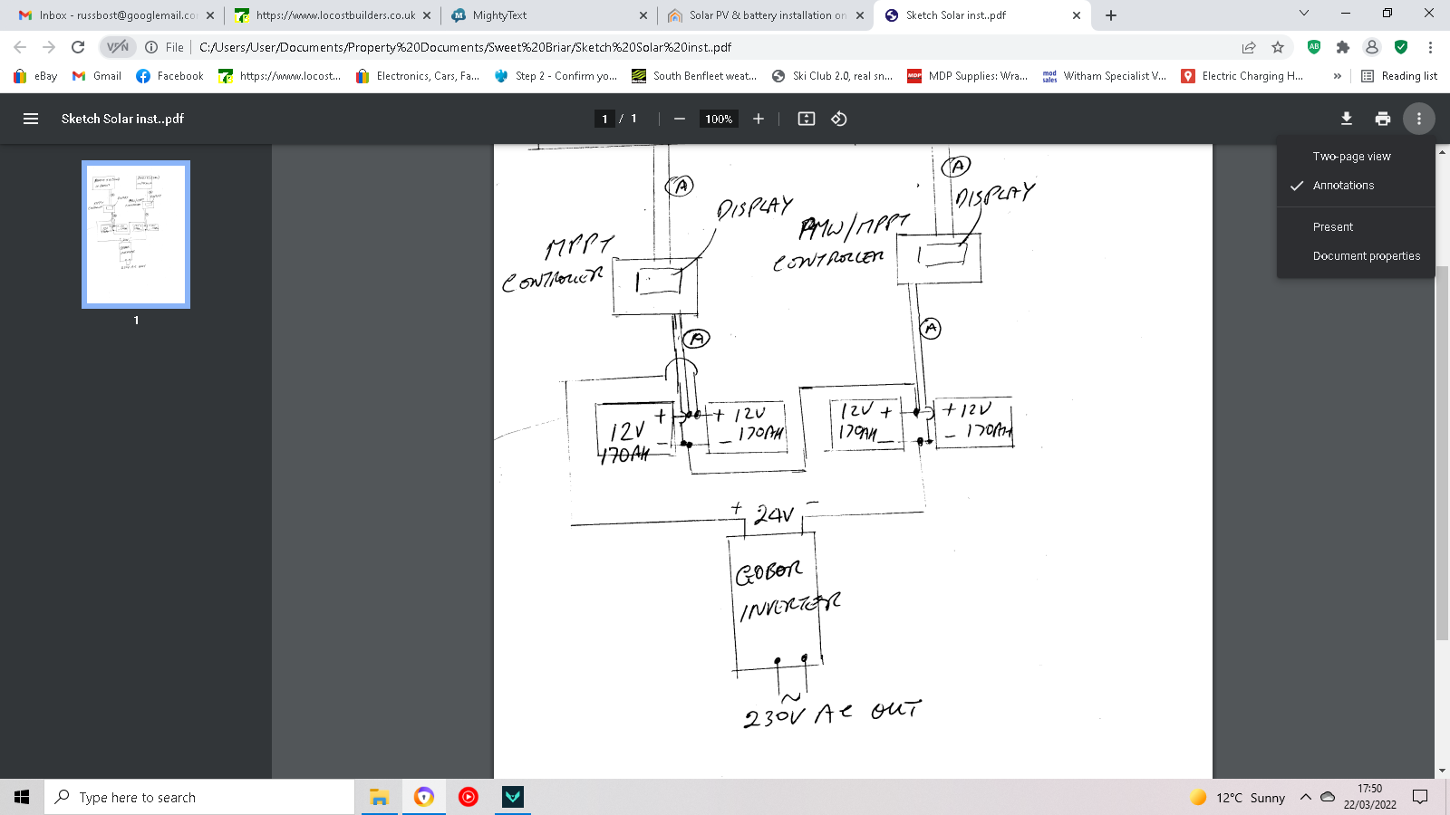
Ive redrawn the circuit correctly & attached it as a PDF Solar Installation.pdf -
Solar PV & battery installation on the cheap!
Solarexploits replied to Solarexploits's topic in Photovoltaics (PV)
You're quite right, I have drawn it wrong! That's what happens when you rush things! The 2 charge controllers are in parallel with one another charging the batteries at 24V. I'll redraw later & repost it The panels have a max o/c voltage of 44, opt. op. volts of 36V, both controllers have max input voltage of 50V, so everything should work fine together at 24V, which it seems to. I think basically I have a lot more available power than I'm using, at present, recent sunny weather, I'm not using the overnight charger which is available for 4 hours at 5p/unit, at all, so there is also spare capacity there My initial idea was to get it all working & see what I'd got in terms of operating capacity, I had already worked it out very approximately, but there are sooooo many variables involved, particularly with whether the sun is shining or not, that I was trying to overallow. As I still have 4 more panels to go up, & at present none of them are permanently fixed & are at too shallow an angle &/or not ideally placed it looks as though I should have a lot more capacity to come I want to keep the fridge & fridge/freezer on grid at present certainly at least until such time as I feel the system is 100% reliable & I'm keeping the large (but relatively temporary) draws from stuff like cooker/kettle & my garage with compressor & welder on grid as a lot of that usage is already covered by power from the existing MCS grid tied array & I didn't want to get into the realms of needing a huge, expensive inverter to handle high loads that are, by their nature not drawn for that long -
Solar PV & battery installation on the cheap!
Solarexploits replied to Solarexploits's topic in Photovoltaics (PV)
When they are charging, say voltage is down at 24 or 25V, both of the controllers are working & I'm getting around 20A on one string & around 10-12A on the other, so, thinking about it, it would make sense oif the MPPT unit has 28.4V set as the float voltage, then if it achieves that charge would kick in & out at lower level simply to maintain that float voltage? & the other unit would drop out as it "sees" a voltage above it's float voltage? I'll try & get a look tomorrow or Thursday & reset the float voltage of the lower unit, see what happens then - I'll report back in case it helps anyone else in future! -
Solar PV & battery installation on the cheap!
Solarexploits replied to Solarexploits's topic in Photovoltaics (PV)
I had no idea how to upload a file to here, so see screengrab below! I'm measuring amps in any one of the 4 positions shown, simple clip on inductive ammeter. The voltages I've been giving are those shown on the display screens of the 2 controllers. When first connecting up those screens show battery voltage of whatever you're powering them with, once panels are connectedvoltage rises to, I assume, whatever it is charfing the batteries at. I have now checked the Giant of Sun controller & that has float voltage set at 27.4V (seems a little low?) factory default, the other MPPT controller, which I've now discovered is an MCU unit, I think float voltage is 28.5V, but can't find the instructions to confirm - I've definitely seen at least 28.4V on that one. If float voltage is set at 27.4V on the other unit would it then stop making an output if it sees a voltage of over that?I believe I can adjust that higher to make it match the other unit Still doesn't explain why the MPPT unit kicks in & out when at high voltages, could that simply also be maintaining a float voltage? In which case I can draw substantially more from the batteries than I currently am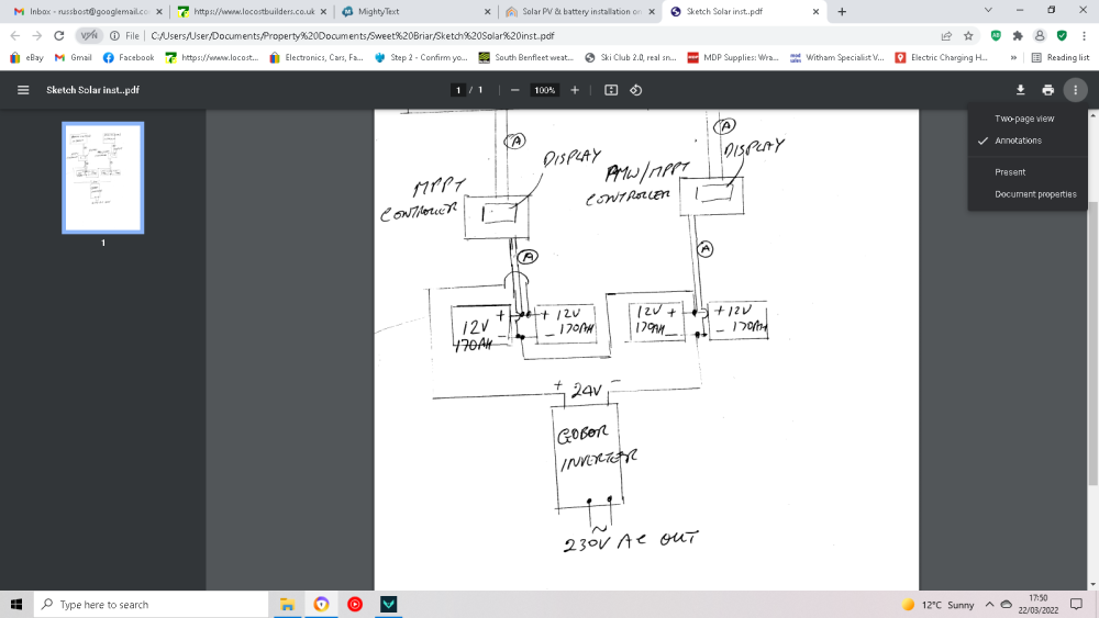
-
Solar PV & battery installation on the cheap!
Solarexploits replied to Solarexploits's topic in Photovoltaics (PV)
Ok, got some slightly odd stuff going on with the controllers, appreciate any advice. I have a simple clip on inductive ammeter which I use to check what's going into the controllers. Once properly sunny on the panels, the 4 controlled by the MPPT controller have around 20 A & the 2 with the Giant of sun controller around 10A, but as the voltage stored builds up, to around the 28V or a little above, the MPPT controller starts to cut in & out, roughly once a second, so, ammeter will jump from zero to 10+ then back to zero, once voltage achieves around 28.5 the controller on the 2 panels, appears to cut out completely, ie not recording any amps on the meter, tho' still showing around 27.5V+ on the display & the display shows it to be working, ie showing flow from panels to battery Is the above normal? The MPPT controller cutting in & out suggests it's registering over voltage or current, but display never showing above 28,5V & both controllers are supposed to be rated at 100A, I've never seen more than around 20 on the meter. I'm guessing the 2nd controller cutting out once volatages are high could be simply that it's registering no further top up to float voltage required & therefore cuts out until voltage drops back a little? Just had a look at some of the Pi stuff - I think that may have to wait a while!!! Apologies for numpty questions, like I said this is all new to me & whilst I have good engineering & general electrical knowledge, intricacies of controllers & the like are outside my experience -
Solar PV & battery installation on the cheap!
Solarexploits replied to Solarexploits's topic in Photovoltaics (PV)
"There's a great deal of variation from one LED to the next." - Yeah, I did wonder if it was a case of the LED's reacting badly as it only seems to be 2 particular lights that are doing this, I'll try some other LED's, I was more concerned that it might be an indicator of another, underlying, problem, I don't want to burn the inverter out! If it was likely to simply be an issue of the suppy voltage from the batteries, being around the manufacturer's ceiling I think I can adjust that down on the controllers "The Victron Battery Monitor is about the only off-the-shelf product I know of that matches what you're after. £190 is a bit steep I'll agree. How familiar are you with the Raspberry Pi? For £30 you could probably piece together a battery monitor using a 4 channel power monitor or a Hall Effect Current Sensor if you need more current. You could also add a relay board and get it to switch on a charger - the sky's the limit if you can scribble some code!" - Really don't want to spend £190 just to save walking outside & lifting the lid on the box! - kinda counter productive when the aim is to reduce costs, I also wasn't sure if Victron stuff only worked with other Victronstuff, rather than any other. I had wondered about Pi/Arduino, but know virtually nothing about them, tho' I did learn code back in the days of Fortran, so have a basic understading, just no idea how to apply it in the medern world! Can anyone recommend a good learning source for Pi or Arduino, online tutorials etc? -
Solar PV & battery installation on the cheap!
Solarexploits replied to Solarexploits's topic in Photovoltaics (PV)
"Don't chance shorting those batteries out, it would be horrible. A 3kW inverter will want to draw up to 120A from the batteries, but don't rate the fuses that way; they are there to protect the cable, so should be lower than the cable can cope with to the inverter. How do you distribute the inverter AC power, is it all regular mains plugs and sockets ? Just because it's not mains, it will have plenty of current and probably no RCD, so take care" Good call, I will add fuses to the battery installation, it could save a fire & save the batteries! The inverter AC power has 2 paths currebtly, one is effectively an extension lead which runs the computer & modem/router, the other goes to an RCD adjacent to the consumer unit which has circuits removed from the consumer unit, lights, alarm & a couple of other small draws, connected to it, so I believe is correctly protected -
Solar PV & battery installation on the cheap!
Solarexploits replied to Solarexploits's topic in Photovoltaics (PV)
I seem to remember Victron are far from cheap? Like I said in the title, not looking to spend fortunes, the concept is to save money on energy, rather than donate it to other sources! 😄 -
Solar PV & battery installation on the cheap!
Solarexploits replied to Solarexploits's topic in Photovoltaics (PV)
I don't recall a minimum current draw being mentioned in the specs, but it has the computer & a couple of other minor draws, maybe 100W consistent, as much as 200W if we have a lot of lighting on, I'm just slightly concerned that as I add more panels & get them properly positioned, then the input to the batteries is only going to go up. Obviously I can add other circuits which will create a bigger draw - all very experimental at present. Regards to quality, it's not one of the ghastly ridiculously cheap ones ( I played with a cheap 12V unit that was dreadful), it claims to be full sine wave & was around £160 IIRC - the make is Gober, which I'd never heard of? -
Newbie into solar & saving energy
Solarexploits replied to Solarexploits's topic in Introduce Yourself
Just put a post up in the Solar PV section "Solar PV & battery installation on the cheap!" shold anyone be intereted in what I'm up to! -
Hi, I'm a newbie to solar (DIY) & have bought 10 x 310W panels & 4 x 12V 170Ah solar deep discharge batteries, all second hand (batteries are 2021, so still pretty much as new). I already have an MCS installed grid tied 4kW array which went in right back at the early tariffs & that also runs a Solic immersion controller which diverts excess power to the immersion heater instead of sending it back to the grid, I'm getting free hot water around 8 months of the year & a reduction in gas usage all year round from this I still have to get 4 of the SH panels up on the roof, but already have had it all working for a couple of months. The intention was to be able to go partially off grid, I currently have all lighting & the computer & a few other small draws all running off the panels/batteries. As I'm on the Octopus GO tariff, I get 5p a unit power for 4 hours overnight so I have a large 12/24V ROHR battery charger to top the batteries up overnight if necessary I'm running thge system at 24v so risk of electreocution is low & able to handle stuff myself, the panels are on 2 separate arrays, 4 on one & 2 on the other, running a "Giant of Sun" cheapy controller on the 2 x panels, which claims to be both PMW & MPPT - my understanding here is limited, but surely it can't be both? & a generic MPPT controller on the 4 panels (no brand name). The 4 panels are in parallel & the 2 panels are in parallel which gives correct voltage for the controllers. & the 2 controllers are in parallel charging the batteries. The batteries run a 3kW (max, 6kW peak) Gober inverter, which was a fairly cheap Chinese (I think) jobby, buit seems to generally work well so far - long term reliability may not of course be so good! Couple of questions, when the panels are in full sun & working well I'm getting charging at around 28.5V, which should be fine looking at the input spec on the inverter, but when charging this well, some of my LED lights in the house flicker, presumably being caused by the inverter, tho' it's still showing 220 - 230V output - I believe both of the controllers are adjustable to output at lower voltage, tho' not played with this as yet, is that likely to stop the flicker on the led's? or any other ideas as to what could cause this? Secondly, at present, I can only monitor battery voltages & charge amps etc. by physically going & looking at the installation, readily accessible, but still a pain. Is there a reasonably priced monitoring system which would send bluetooth signal to my phone to monitor &, better still, is there anything which would trip a relay to bring the battery charger in if voltages drop below a certain point, if we had particularly crap weather for several days for instance Any ideas/info welcome, like I said, I'm new to all this & getting on the learning curve
-
Newbie into solar & saving energy
Solarexploits replied to Solarexploits's topic in Introduce Yourself
I already have free heating on the immersion for around 8-9 months of the year as I have a 4kW grid tied array put in back at the start of the solar tariffs, so long since paid for itself & now earns me a couple of grand a year! The Solic takes any power you're not using from the array which would normally go back to the grid & reroutes it to an immersion heater in the hot tank, saves probably around 6kWh in gas per day, even in the depths of winter it still gets a few hundred watts into the tank & should get more as I take more circuits off grid using the new panels & batteries -
Hi All, I'm Russ, always been an ardent DIY'er, qualified engineer by trade, now largely retired. I've undertaken many home extension & refurbishment projects, I still run a residential rental & sales business. Currently helping out with daughter's dormer extension/rooms in the roof, Boy how building regs/architect requirements have changed!!! There's enough steel in the top of their roof now that you build a supertanker from it! Main reason I've joined is to pick brains & share info about all things solar. I have a 4kW grid tied array which was installed right back in 2010/11 when FIT prices were crazy high. It's long ago paid for itself & now makes/saves me around £2k a year. Obviously I can't extend it as it's already the max for grid tie system & certainly don't want to lose the FIT I'm on. Recently installed a Solic immersion heater controller which is using the surplus kW that used to go back to the grid to give us free hot water for most of the year - it's fairly obvious where ALL energy prices, not just gas, are going in the next few years Current project I've bought 10 second hand 310W solar panels & 4 x 170Ah 12V solar lead acid batteries & am playing with various installation ideas to take some of the circuits off grid (which will give us further kW for free hot water when solar output is low) using a 3kW cheapy inverter & possibly use some direct 24V heating to give some general background heat I'll be posting up some info on what I'm doing in the PV section & no doubt asking some stupid & annoying Q's - please be gentle with me!