LinearPancakes
-
Posts
55 -
Joined
-
Last visited
Everything posted by LinearPancakes
-
Latest update on this, in case it's helpful for anyone in the future. The installer was confident that Leca wouldn't go down either and there wasn't enough space spare to insulate with Chimwrap or a mineral wool wrap either. So we're not going to have insulation there. In terms of airtighting the outside of the flu liner, given space challenges around the stove, we're just going to have to bung up around the bottom of the liner with mineral wool. Not ideal, but that with the limited space between the liner and pots, the cowel on the top and the stove being in the recess, means there will at least be resistance for any air trying to escape up. A separate issue we've encountered, which seems kind of obvious with hindsight, is that inset cassette style stoves are inherently bad for airtightness. That is, they're not a closed system: - Direct air in, connects to the frame, not the cassette. And there's a big gap, so you're basically connecting it to your room. - We're solving that by adding a shutoff valve (Lindab DSU) on the air inlet, so we can close that when not in use - The flu is directly connected to the cassette. However, the cassette takes air in from (for our unit) 3x places. Two can be closed with the controls on the stove. One remains open, which means again, connected to your room. - We're planning to solve that by sealing the responsible holes when the stove is not in use, in a way that's both obvious and easy. If we'd known all this upfront, I think we'd have probably done more research into which stoves are suitable for use in homes attempting to be airtight. A freestanding stove within the fireplace would probably have been a better option. But it's probably going to be good/easy enough in practice and it will look/feel great, and very nice to have a backup heat source when using an ASHP. Not quite installed yet, but should be soon. I'll send a finished picture. Picture of the blower test attached!

-
After a bit of research I realise we could install a register plate below the lintels to seal it. Then to address the moisture issues, fill around the flu with Leca. Seems like some kind of insulation around the flu is important independently to improve the liner performance and lifetime. Will discuss with the installer soon. The installer wasn't keen on my first version of this solution, using vermiculite, as: - It can turn into a soggy mess if there's ever a water leak - Hard to get it to go all the way down reliably when the pots are about 8" and the liner 6" Hoping the extra weight of Leca will help it go all the way down more easily, if using 4-10mm, and the better performance when wet will be suitable.
-
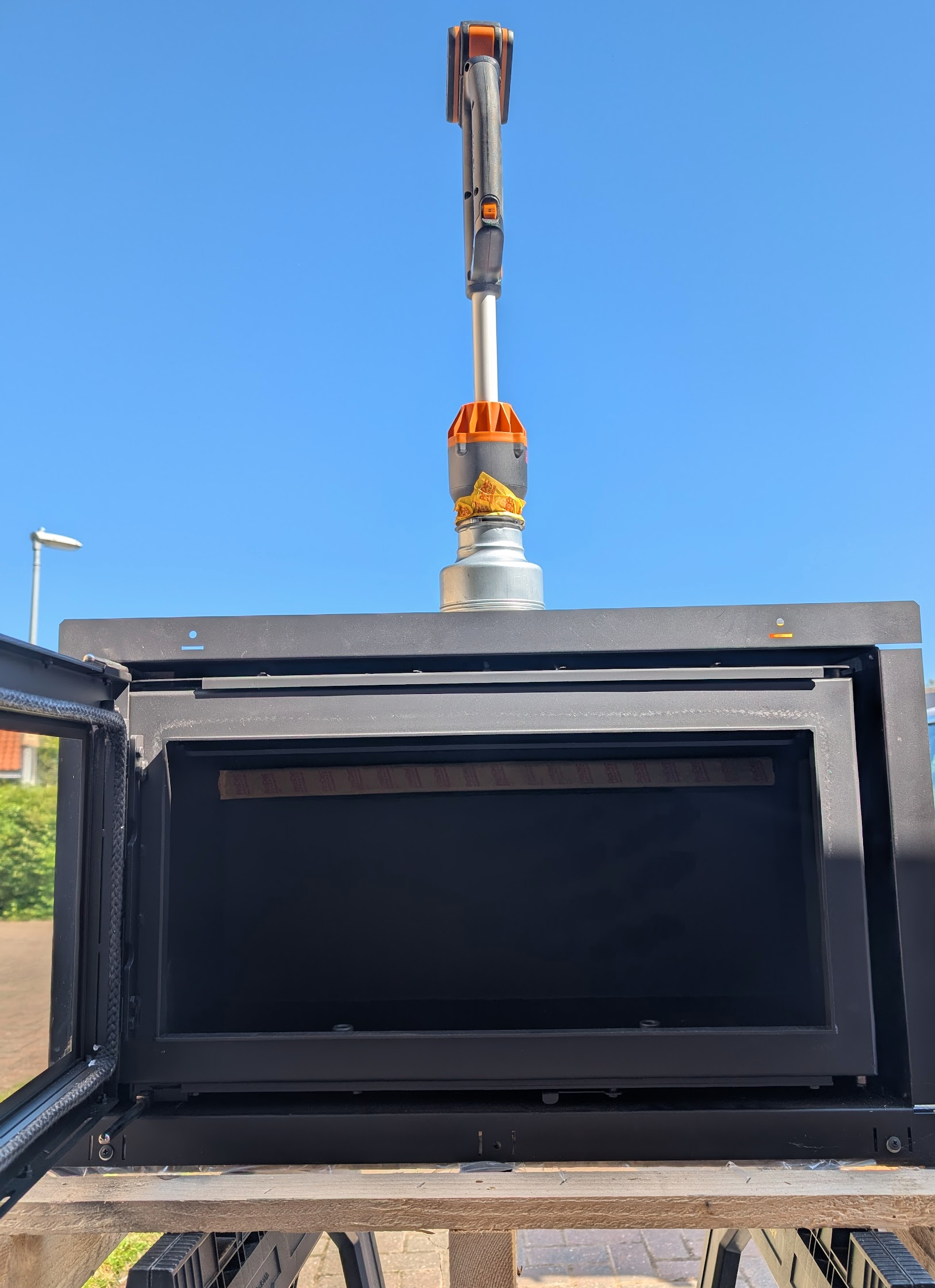
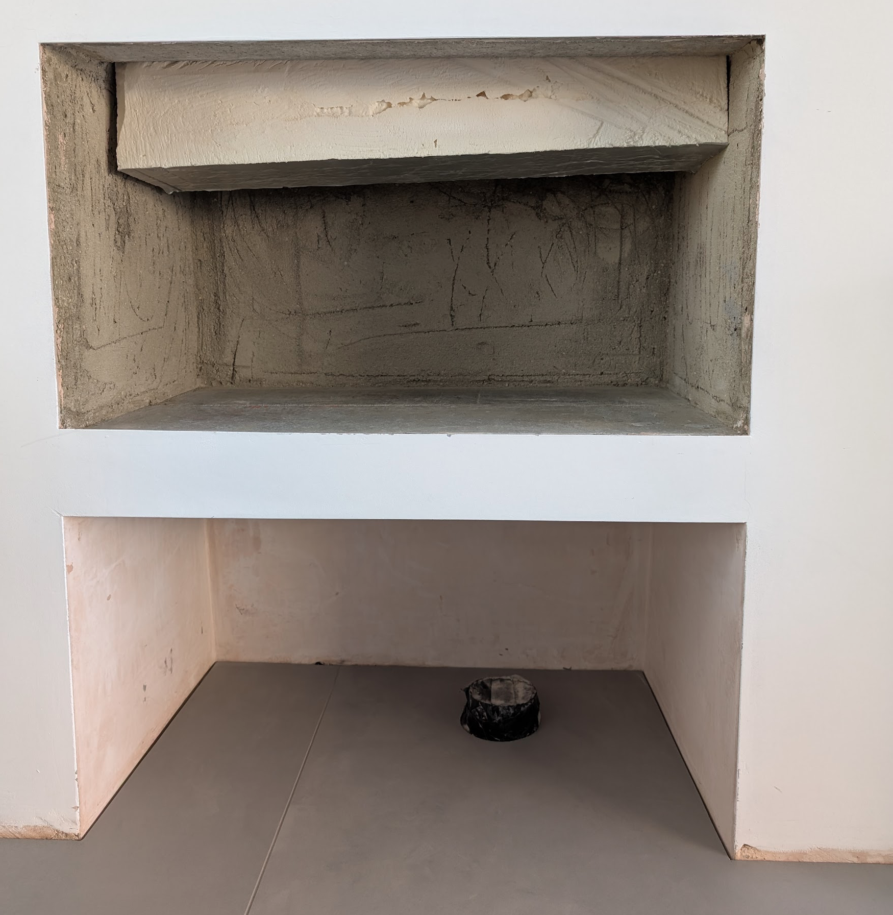
We're finishing the last details on our home, on which we've attempted to make as air-tight as possible. One of these details is the inset cassette, direct-air, wood burning stove. Originally there was a fireplace. We've had brickwork done to accommodate a stove. We installed a 100mm diameter duct through a hole in the floor through to the vented space underneath. (Yes, we need to make a hole through the lintels 🙈) The plan is to line the flu, and connect the stove to the flu liner and 100mm air inlet. Since stoves have airflow controls, I would imagine that this part of the system is reasonably closed air-wise. The detail I'm stuck on is the gap between the flu liner and the chimney pots. This will open up into the area where the stove is installed. Even if this area itself is airtight, I imagine the stove will not seal tightly to the wall, and there are likely gaps in the stove frame. Originally I was thinking to seal between the flu liner and pots, using a suitable high temperature sealant, near to the spigot on the stove. This way, continuing the airtightness layer around the flu. However, our stove installer is recommending against this, due to risk of condensation build up in the chimney. I can only imagine the increased risk, compared to the chimney being blocked up without a stove at all, is because the flu liner is metal and will get colder causing condensation on that. But.. to avoid the condensation, airflow would be required, which would by definition mean an air-tightness issue. And if the rest of the house is pretty tight, a. this seems like a big shame, but b. would there even be a challenge getting sufficient airflow there, as where will it draw air from? (It will probably find a way, by pulling air in from weak spots causing draughts) I'm starting to think maybe this is the price you pay for having a fuel burning stove in an otherwise airtight home. It would be a shame to abandon it now and install an electric feature heater - it would be so nice, and be a nice backup for electricity given we're on a ASHP now. Has anyone hit this before? Anything I'm getting wrong about this?

-
Thanks! As proposed, strip of 15mm ply about 270mm tall all the way along. Needed two pieces to cover the length so had the join behind the middle unit. Plenty of wood glue on the back, longer screws at vertical joist positions then shorter screws nearer the edges and evenly spread out, avoiding where I'd need to fix the mounting plates - mounting plates about 1/4 from the top of the ply so as not too close to the edge. After about 2-3 days for the glue to fully dry, covered in a sheet of class-o high temp foil tape to reinstate some of the fire performance. Pilot holes of the correct diameter and depth for good measure. Connected the units through the sides and put an extra L shape bracket at the top of each unit.
-
Thanks for the advice guys. Worked out great, 4x units up nice and solid. (knock on wood!)

-
Thanks so much for the fast responses guys. Great suggestions. I'll run with the continuous strip approach. The existing ply will have been screwed through the membrane at stud locations anyway, so no harm adding a few more. I'll check the brackets & unit to see if I can get away with 18mm ply instead - much easier to get hold of than 15mm. I suppose fire retardant ply would be good here try to preserve the fire performance as well.
-
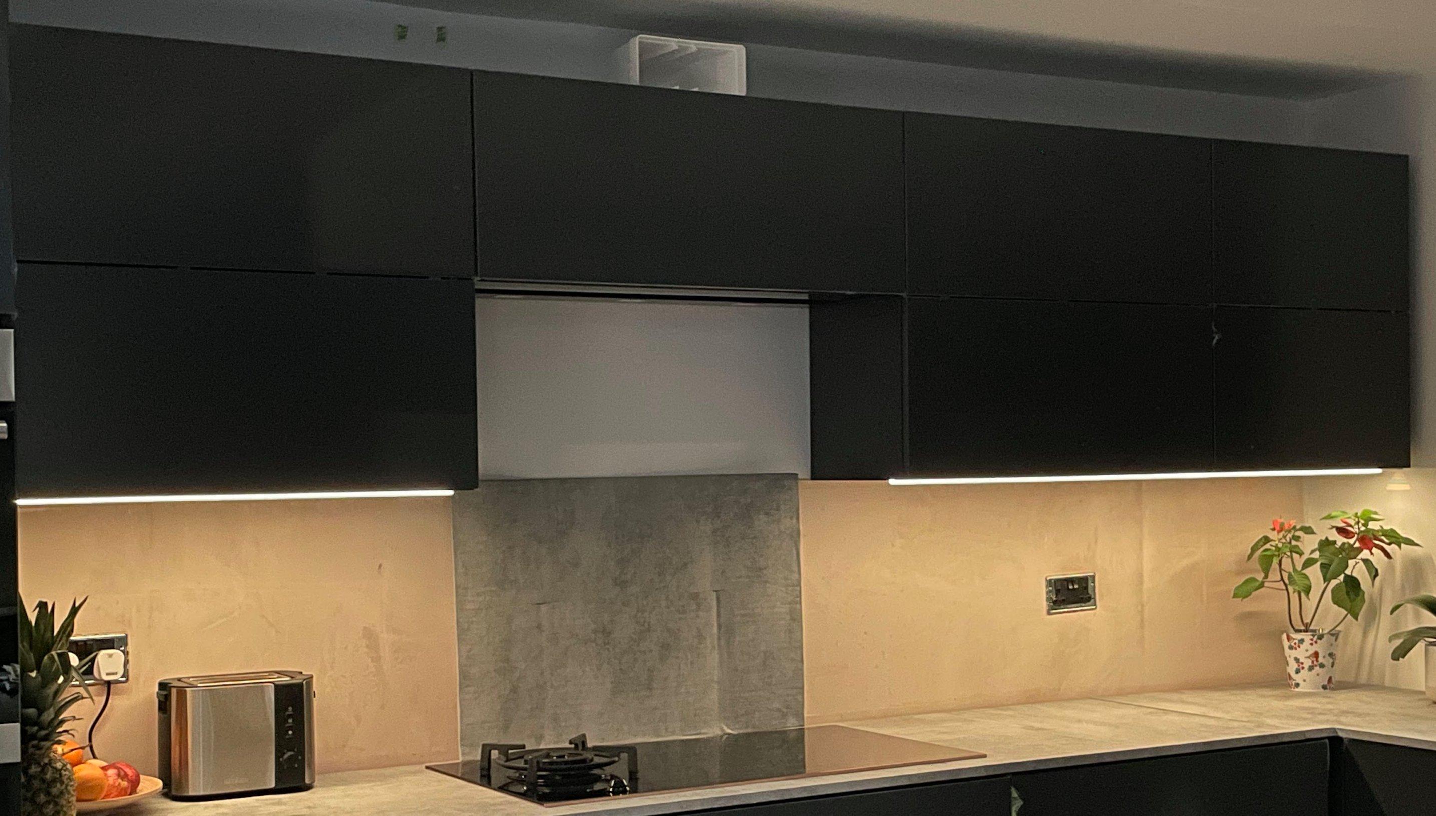
We have some DIY kitchens wall units to hang. They have 2x wall hanging plates per unit that are first screwed into the wall. Our wall is timber frame with air tightness membrane, 18mm plywood, 12.5mm plasterboard and ~3mm skim. The air tightness membrane is directly behind the plywood, so I don't want to screw in too far and make holes. This means 35mm long screws to account for the screw head protrusion of ~2mm. Obviously this is not a particularly long screw and only 18mm nearest the tip will be really gripping anything. Given they're heavy, slightly deeper than usual (320mm) wall units, I'm tempted to: * Cut away the plasterboard for a rectangular area around where the wall hanging plates will go * Glue and screw 15mm plywood to this area, leaving a consistent level The extra plywood would bond really well to the existing plywood behind, meaning there's 33mm of really good hold from the combined layers of plywood. But this might be overkill. I'd appreciate any insight.
-
Or.., given the challenge of installing OSB (nowhere to fix it to), a suitable size & thickness of celotex might be a good option. Could tape it to frames, side window without damage. It should help take the edge off the forces/deflection and would protect the glass from anything flying around too. 🤔
-
Obviously the window supplier said it will be fine, and referenced how they'd seen videos of this type of toughened glass bending like a banana before it cracked. They also cited previous installation of the lift & slide in costal areas with high winds. So I think the weak spot is probably the separate single window, as it has a thin aluminium frame and is not internorm, so will not have been through the same design verification process. I'll try to just not worry about it. Unless I hear of 80+ mph gusts coming, in which case I may try to find a way to fit some OSB to the outside of the single panel window. 😅
-
Thanks @Conor. I've asked for details on this topic from the window supplier. I'll report back what I find out. Hopefully, as you say, the software they used to spec out the Internorm lift & slide would have taken these things into account. The frame on the slider certainly is chunky, so not worried about the frame. The window is unfortunately not Internorm; one of the few aluminium frame windows in our build. Still triple glazed - not sure how much the layers will help, presumably a bit.
-
Thanks guys, I'll have a dig into those numbers. Sounds like the window supplier should have requested we co-ordinate with the SE, given the size of the panes involved? I guess if there's no regs for it, they'll not volunteer to do that. I admit it's just not something I'd thought about until I saw the reflections shift on the glass.
-
In the recent winds, we noticed a lot of bending on our large triple glazed panels. 1x aluminium framed window 2360x1550, 2x Internorm sliding door panels 2320x2100. We're mostly west facing, so getting a lot of direct wind in storms. We were up to 54mph gusts last night, though it has been higher in previous years. Obviously they're designed to flex, but it does make me wonder how much they'll withstand and what impact it will have on the containment of the gasses. It was pretty worrying to see. Most aspects of the building structure are designed/checked by the structural engineer, but I don't think anyone really owns checking these details. We specified the size, the window company supplied them. Any idea where I can see what the maximum rating should be? We could make some marine plywood sheets to fit externally in extreme cases, but the frames are aluminium and I wouldn't want to be screwing into that.
-
Whole House Cooling
LinearPancakes replied to sargan's topic in Mechanical Ventilation with Heat Recovery (MVHR)
Jury's still out @Nick Laslett - the unit is installed in the supply feed, but the water supply is not connected yet. Will report on any real world experiences. In the current cold snap, our upstairs rads seem to struggle a bit with the 45deg flow temp from the ASHP - probably could have done with sizing them up a little. Hoping using the ComfoPost to warm the air will help a little bit too, or at least offset the cooling due to inefficiencies in heat recovery. -
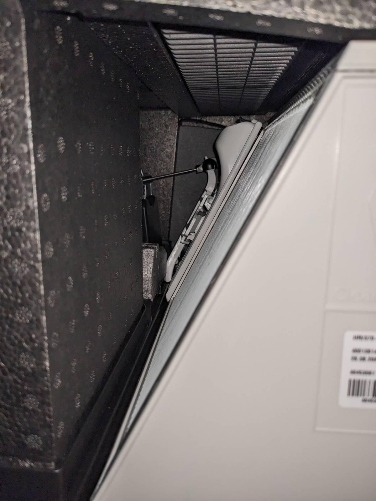
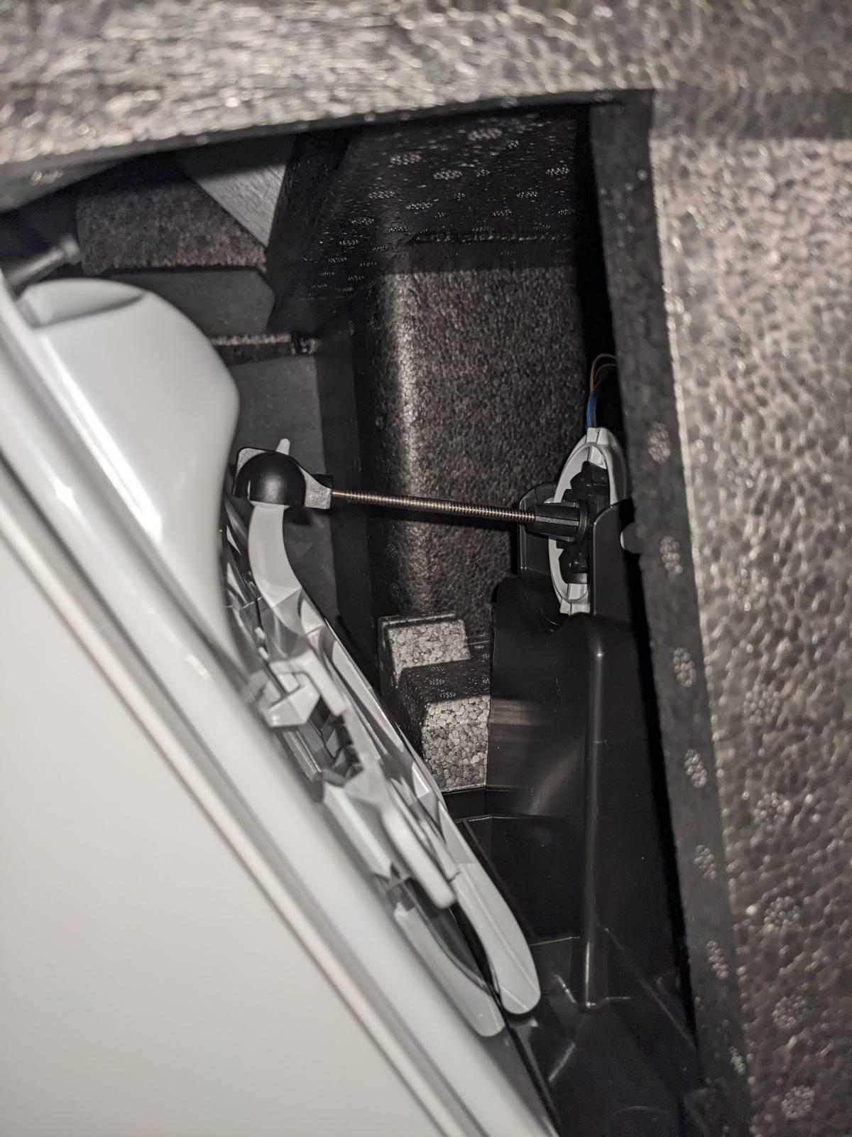
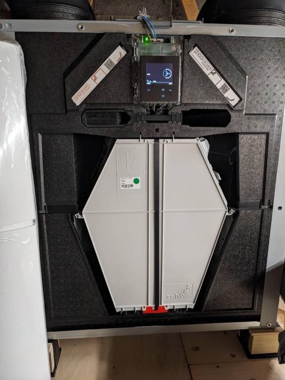
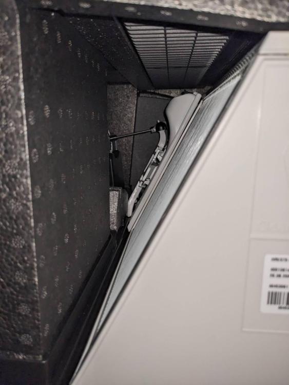
Many thanks for the responses guys. For sure the system is not balanced room-to-room. But the overall air resistance across supply vs extract is pretty balanced, and the machine appears to be adjusting the fan speed to match the flow rates anyway. My understanding is that overall extract/supply flow rates need to be matched to get optimal heat exchange performance. I double checked the connections and pretty sure they're right. It's a right hand unit, so external on the left, internal on right right like the attached picture. I called Zehnder support. He mentioned they once had a case of the bypass actuators failing. I took the front panel off and indeed the bypass actuators aren't doing anything on change - except a brief buzzing noise. From the pictures I could find, it looks like they're both stuck in bypass mode. Hence the limited heat recovery. I'll be in touch with Paul Heat Recovery (supplier) or Zehnder on Monday. Hopefully it can be repaired in place!


-
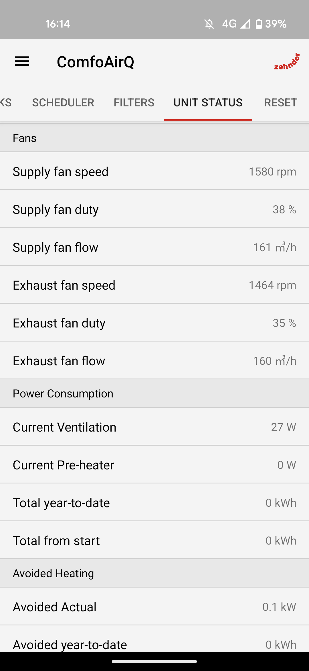
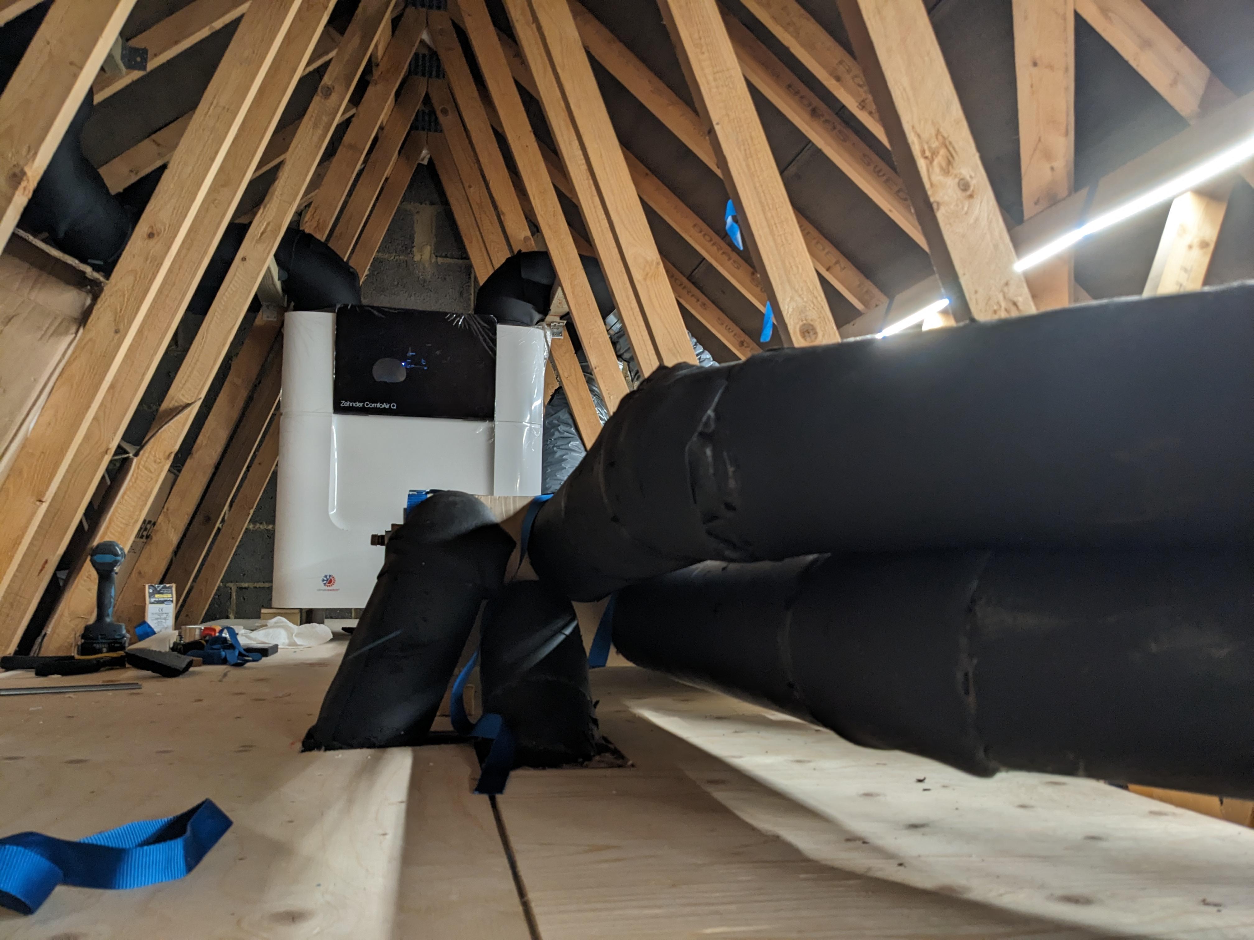
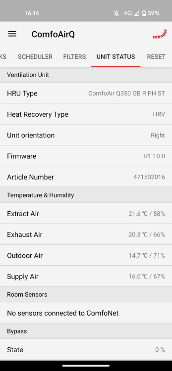
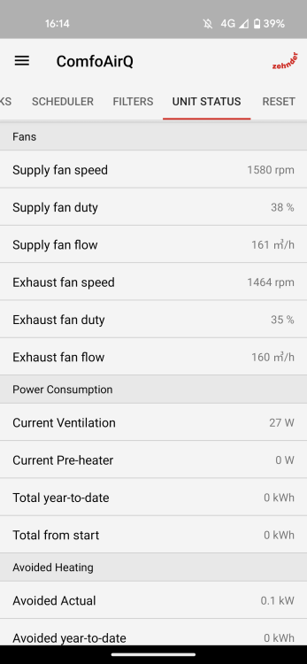
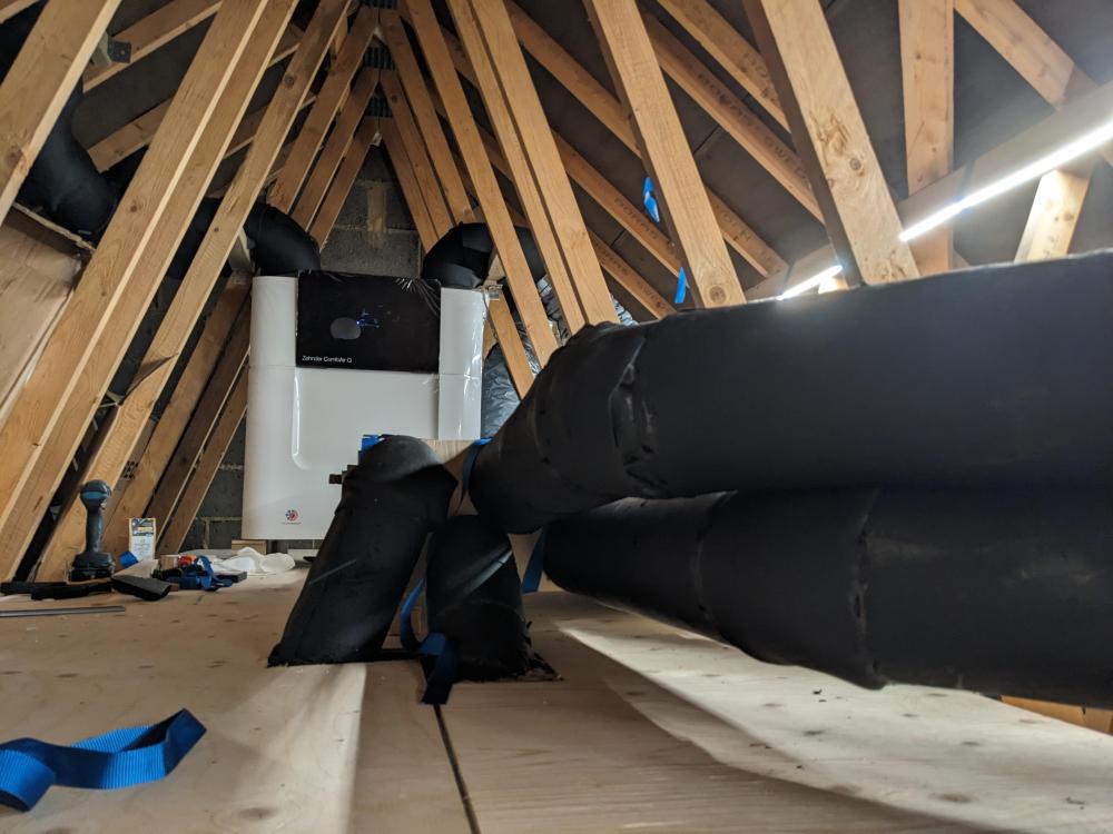
Finally got the MVHR system on yesterday after a lot of work and time. It's a Zehnder Q350 in a cold loft with terminals on the roof and Zehnder manifolds for supply/extract. Ductwork is Lindab steel with varying amounts of armaflex vapourtight insulation in the loft and on supply in the house (also have ComfoPost). Now I still have more insulating and balancing to do, but the heat recovery performance is not what I was expecting. On low (160 m3/h), seeing 21.6 degrees extract, 14.7 outdoor and 16.1 supply. The condensate drain is connected, I've ran the commission programme, covered the whole unit in mineral wood (to test), bypass is disabled. The unit seems be auto balancing the extract and supply flow rates anyway, though I did try covering supply terminals to make sure it wasn't over supplying. Any ideas?
-
You're right, thanks. I believe the last heatwave was 41deg peak and ~25% RH. So in a loft heated beyond that, the RH would be even lower. Looks like the plan for 10mm armaflex + 50mm ductwrap for extract and 25mm armaflex + 50mm ductwrap for supply will not have any significant condensation, even in worst case.
-
Not for certain, but I was trying to pick a worst case. Maybe 50 degrees would be a more realistic peak in a heatwave, but I don't think it would change the calculations significantly.
-
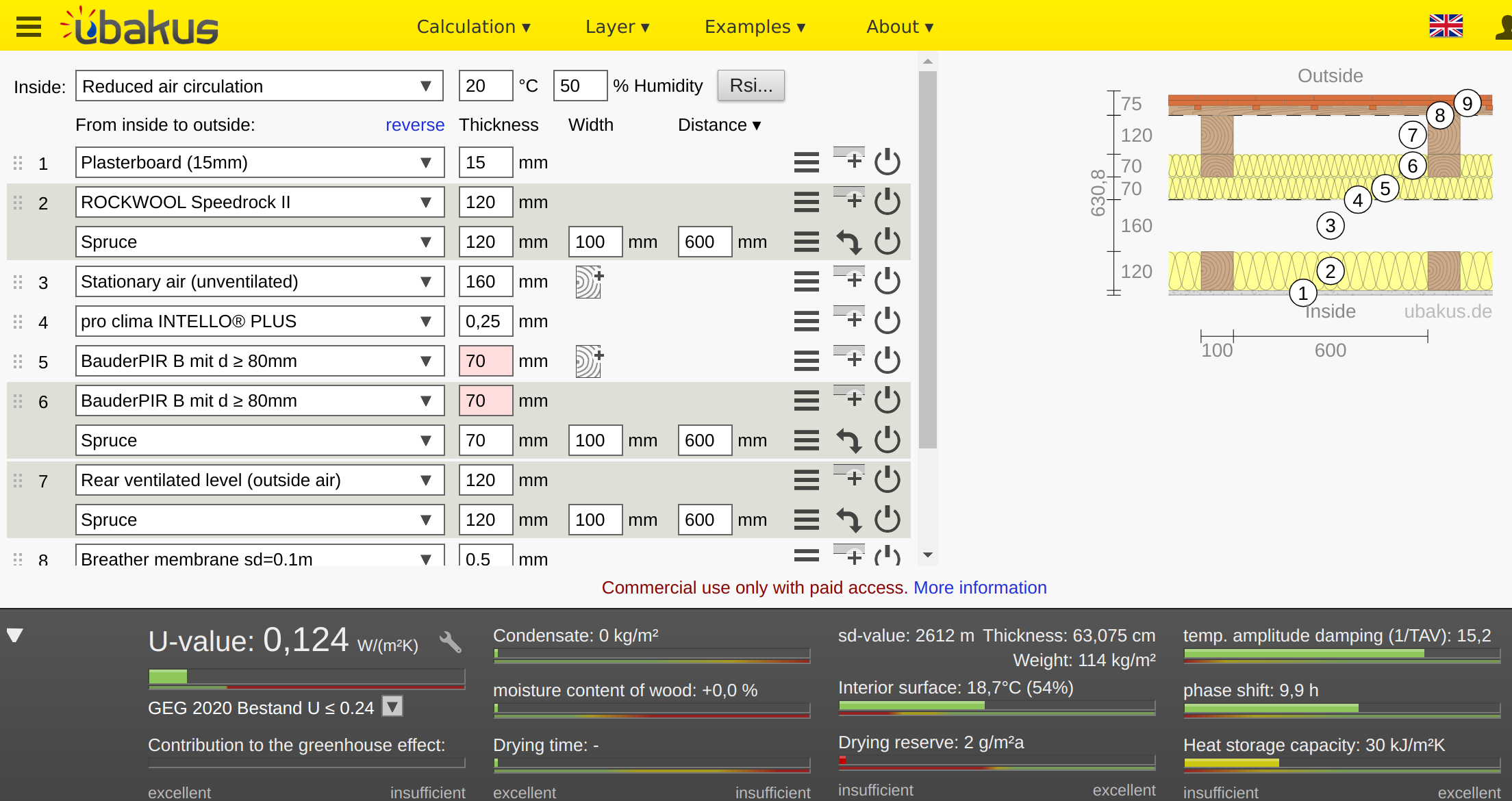
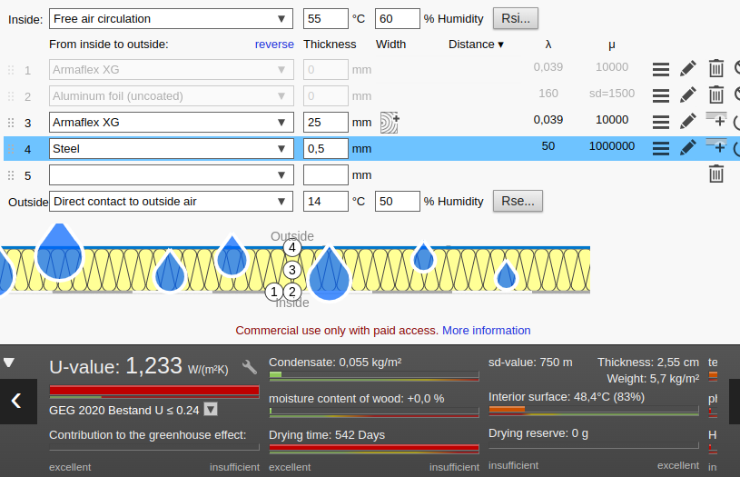
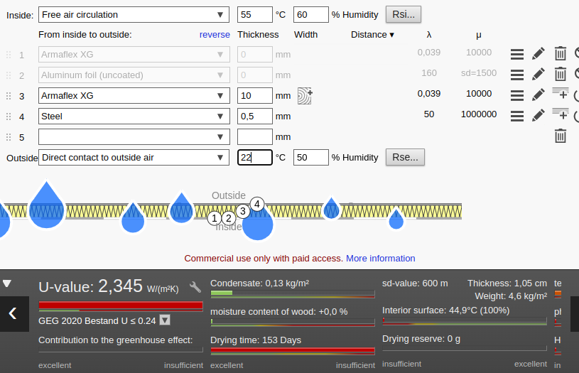
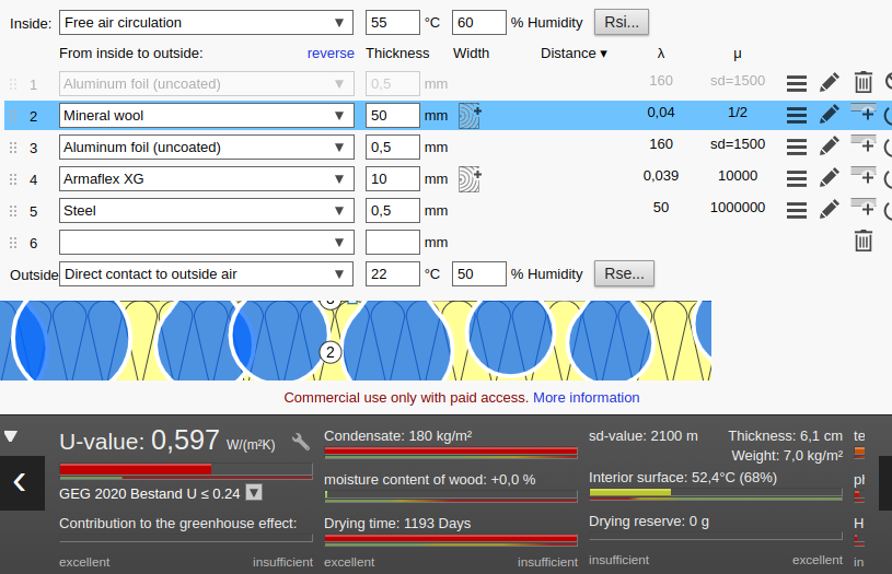
Our MVHR unit is going in our cold loft. To insulate the ducts I'm planning: 25mm armaflex wrap on supply ducts, as these could be cooled to ~14deg in summer due to ComfoPost 10mm armaflex wrap on extract ducts If I've modelled this correctly in Ubakus, it looks like there will still be a bit of condensation on the outside of the Armaflex in the worst case scenario (assuming heat wave, loft getting very hot). Applying a foil wrap outside the Armaflex looks like it will prevent this. Though I imagine it would be tricky to apply this well enough to provide a sufficient vapour barrier in practise. I also bought some foil faced fibreglass duct wrap that I'd planned to use outside the Armaflex to reduce heat transfer where not covered by loft insulation. But condensation skyrockets when I apply a similar setup (mineral wool). Better with foil wrap, but again, I doubt in my ability to make it a good enough vapour barrier. I find this curious, as if there's no condensation build up on the Armaflex. So my questions are: Would you expect the foil wrap outside the armaflex to help condensation that much? Will I get huge condensation issues applying the fibreglass ductwrap around the [possibly foil lined] Armaflex? I guess I could just double up to 50mm armaflex, but it's pretty expensive stuff. I was hoping 25mm Armaflex and then fibreglass ductwrap would be fine. Thanks for any insight you can give. Screenshots of Ubakus attached.
-
We've got an anhydrite based screed down that we're looking to tile shortly. Hopefully all OK from a moisture (will be testing soon) and laitance perspective. Using 1.2x1.2m porcelain tiles, wet underfloor heating and durabase matting. We had two tilers quote. One wants to use 2x coats of primer and cement based adhesive under the matting. The other wants to use 1x coat of primer and Anhyfix under the matting. From what I find online it seems maybe Anhyfix is the preferred option. Though I'm reluctant to ask the other tiler to use something he's not familiar with, and maybe the other option is perfectly fine too? To add to the confusion, Anhyfix is listed as discontinued and out of stock in a few places. 🤔 Any advice/thoughts much appreciated!
-
Non-vaulted roof, condensation risk
LinearPancakes replied to LinearPancakes's topic in Heat Insulation
OK, looking at Ubakus, as I feared, we'll get significant condensation on the membrane, if I entered it correctly: Looks like something like this would be better, and I have a good amount of 70mm Kingspan PIR lying around: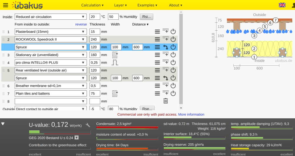

-
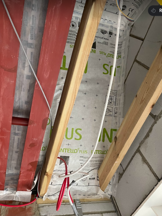
Hey folks. We're nearly done with all of the air tightness detailing in our renovation. One last hurdle is the porch. It's not vaulted, and has recessed spotlights. For this, we're looking at applying air tightness membrane along the underside of the rafters, to have space for two recessed spotlights and avoid them needing to penetrate the membrane. The detail here will be a pain, as we'll need to ensure the gable walls on both sides are also made air tight and that this is tied back nicely to the edge of the air tight layer on the house. You can see the flapping membrane in the picture.. A pain, but do-able I think. What's bothering me is that there was no insulation put above the membrane. So it's just roof, 125mm void, membrane, and then we'll be having mineral wool above the plasterboard. It seems the problems with this are: We shouldn't be insulating all around the spotlights, and if this is the only insulation, we'll have un-insulated areas. That's not going to be a lot of insulation generally. Though it's only a small area. Will it be like a tent? The warm moist air rising up through the gaps, past the insulation to the cold membrane surface and condensing? Seems like it would be better to have say, 75mm PIR insulation between the rafters, leaving 50mm air gap, then the membrane. That would reduce the chance for any temperature differential and mean the spotlights aren't completely uninsulated. Any thoughts?
-
2-core earthed shielded cable, as a 3-core cable
LinearPancakes replied to LinearPancakes's topic in Lighting
Thanks @ProDave. That.. is a good question, to which I will seek an answer tomorrow. The controller I'm using has +24, WW and CW terminals (well, and unused RGB terminals). Would the +24 be the 0V in this case? Or perhaps we also need to ground something? I'm curious how this would still allow shielding to do its job. Is it that most of the "power" is going via the main two cores? (Sorry, I tried and failed to get my head around electron/charge flow!) -
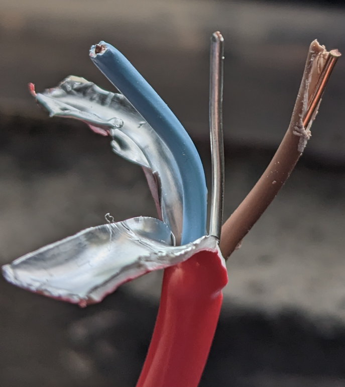
We're doing first fix for a lot of 24V DC lighting circuits. Some of these are tuneable white, warm-white + cold-white, so we need 3-core cable for this. Since there are a lot of long cable runs from controllers to the led-based lights, and the controllers use PWM at probably 10kHz-20kHz (more than the usual 1kHz of Hue), we requested shielded cable to minimise any radio interference. We're also using aluminium profiles for the strips to help with both heat dissappation and shielding. The electrician told were using 4-core cable as that's what they could source, but on checking the cable positions prior to the plasterers arriving (tomorrow 😳), I've noticed they used only 2-core cable. It does have an aluminium earth that I've learned they were told can be used as another core, but it's in direct contact with the aluminium shielding. In this arrangement it would seem that not only do we not get the requested shielding, but we maximise radio interference by using the shielding as an antenna. I see three options: 1. Use a fixed white tone (only use two of the cores) 2. Stop worrying and use the earth/shielding as well 3. Get them to replace the cables Problem is, I don't like either of the options... The electrician has indicated the lighting cables are away from 240v cables and the different frequency from the WIFI should mean there's no issues. Sure the plastic part of the cable sheathing will attenuate, as will plasterboard, etc. But there's no getting around that there will be a lot more radio waves emitted than if it was a proper 3-core cable with shielding. I'd have preferred unshielded 3-core cable to this arrangement, as surely using the aluminium shielding will help emit. But I don't know enough to know if these are rational concerns. Anyone able to offer any further insight?

-
Backer boards for large format tiles
LinearPancakes replied to LinearPancakes's topic in Bathrooms, Ensuites & Wetrooms
Many thanks @Nickfromwales. I'll check the centres of the studs later today. They "look" like 400 from my pictures, but can't be sure. Do you think 12.5mm mr pb would still be strong enough, if studs are at 400 centres, even if not perhaps bomb proof? 😅 Got a few areas that are pretty tight and every mm will help. Our tile provider informed they're only 14kg/m2, so if not skimmed we should be ok weight-wise. Sound-wise, I'm happy with regular pb acoustic properties. We have soundboard on the bedroom side anyway. It was more not wanting to have the low density of XPS only in some places. -
Vaulted roof insulation condensation risk?
LinearPancakes replied to LinearPancakes's topic in Heat Insulation
Many thanks guys. I'm sufficiently comforted to move on to the next challenge in the build. 😅 I also spoke with Ecological Building Solutions, who we purchased the membrane from, and they also said should be fine condensation-wise. They did point out that when using foil faced rigid insulation the intelligent features of the intello plus membrane aren't really being used much anyway, which is interesting.