vala
-
Posts
246 -
Joined
-
Last visited
vala's Achievements
Regular Member (4/5)
28
Reputation
-
Won't be doing this. as mentioned old decking got chewed up by rats and having the patio on pedestals gives them somewhere to go when it's cold. so need to find the solution to hopefully keep the patio near to internal FFL.
-
My existing timber decking's joist got chewed up by rats and it's time to get this area sorted. The DPC looks to be a couple of courses below the rear door opening which, now the decking has been removed is where the old patio was. I'm aware I shouldn't really be building externally above the DPC level, however if I install an ACO drain, the full width of the patio against the house would this suffice, and allow me to safely raise the patio level to near internal FFL? could even step away the ACO by 50mm or so if needed.
-
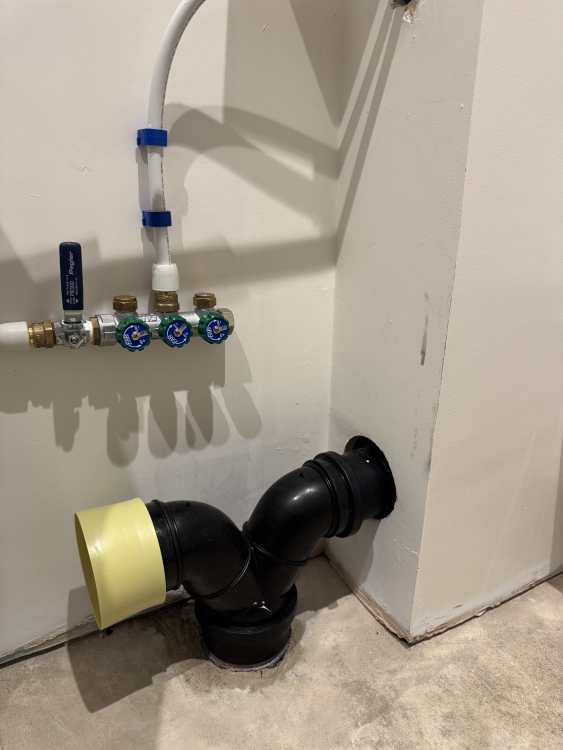
Yes, can confirm mine too has a hole in the centre of the top part. to reduce wastage and returning items I'll use the parts I already had on order and will get the standpipe @Nickfromwales linked to. Will use the dual appliance spigot I already have. as it's still a minimum of a month (most likely longer) till I finish making the last 2 units so I'll have some time testing it without any access issues if it needs to be changed to how @Nickfromwales suggested with the y branch.
-
Noted. The gurgle we experience currently with our existing set up in the kitchen which is using the same paperwork as was here before we bought the house. this is a sealed spigot under the sink attached to the sink waste and the noise comes through the strainer. i was hoping the air break in the top of these spigots would prevent that along with using a seperate standpipe. thanks for your help on this!
-
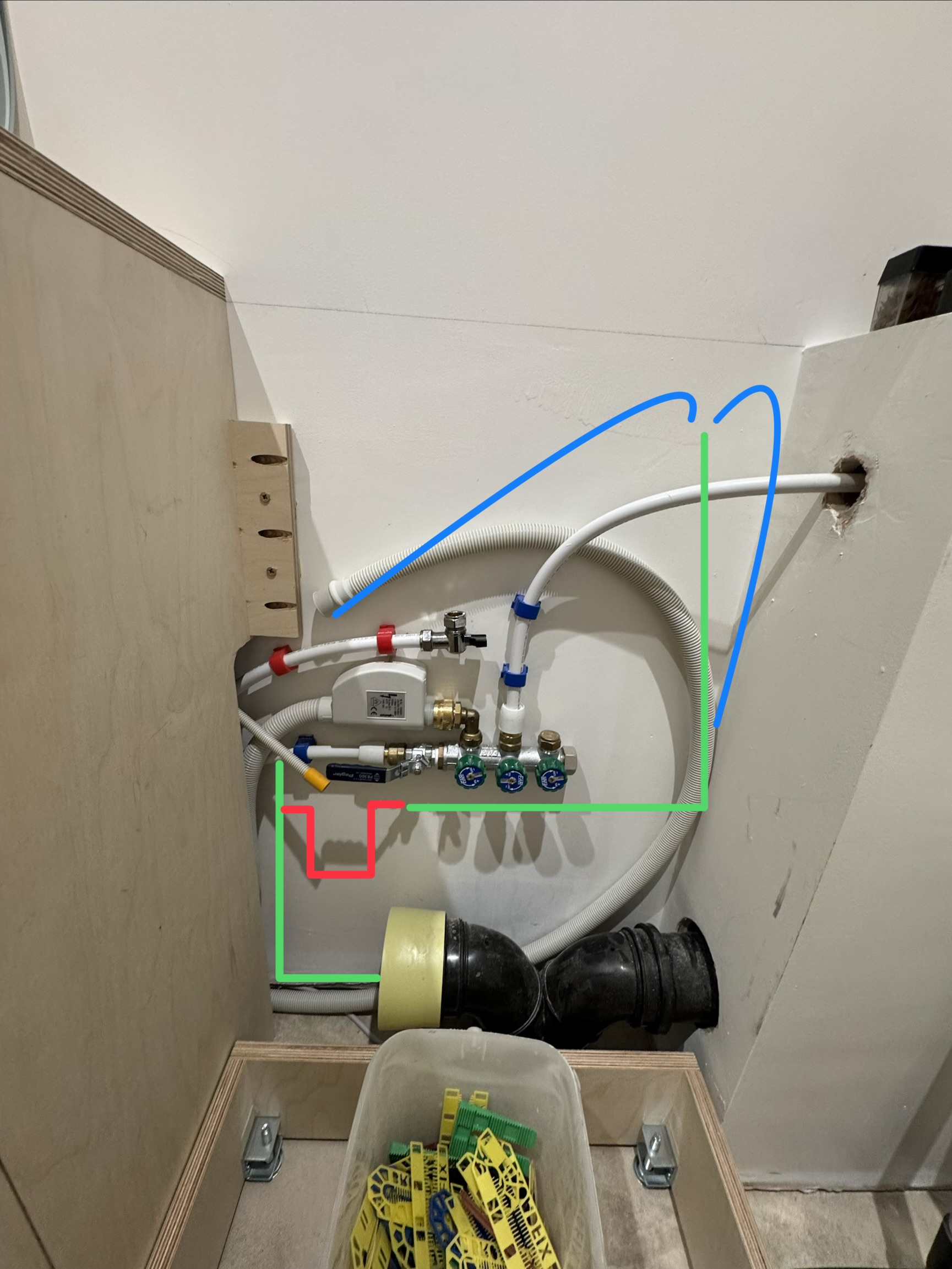
that black connector is for the toilet waste as well. From the ground is the 110mm pipe to the sewer. The black connector is 110mm to 90mm. The geberit pipe out of the toilet is 90mm as standard. I've already had on order a reducer to 40mm, elbow and tee piece and this is being delivered on Monday, to come off from the yellow bung. if 300mm is enough then I have a dual appliance spigot already here? https://www.screwfix.com/p/mcalpine-twin-hose-connector-40mm/206hr use this instead of tbh y branch?
-
Thanks. i should have mentioned I need a sink waste here as well. so where the I tee'd off for the running trap, I was going to run the sink waste to there. i'll measure up where you've drawn but off the top of my head that's probably about 300mm from the appliance spigot to the p trap. would that be enough overall length of pipe?
-
Green line path of 40mm pipe. red line possibly a running trap. blue lines the drain hose from WM & TD. everything unfortunately a lot tighter then I'd hope for due to the change from stacking to side by side.

-
Originally intended to stack washing machine and dryer so had plenty of on wall to tee off to sink and a standpipe for WM & TD. This would have allowed a 700-800mm pipe including trap. However now the time has come to install, decision has been made to fit the appliances side by side. This has reduced the available space and now a seperate standpipe cannot be fitted. I've read the reason standpipe are around 700-800mm, is due to discharge rate and allow drainage should the rate be slowed down for whatever reason. If this is the case would it be ok to get that overall length of pipe, however have it at a 90° bend? Maybe use a swept bend rather then a tight 90°?
-
If you need a guide for purging air out of the loops, we have done it using the method describe in this manual from Wunda. Noticed a fair bit of air coming out even from loops we thought had been fully purged. May be worth a try. https://www.wundagroup.com/wp-content/uploads/2019/10/M07-generic-Wunda-premium-Manifold-25-4-2018.pdf
-
@JohnMo thanks for the advice. i will do as you say and leave it to get up to temp. with regards to the above do you mean to trim the flow rate up or down slightly? i don't have individual thermostats in the rooms as it's all open loop. and decreasing the flow temp (at the manifold) would affect all loops.
-
Little update from the weekend. so I've used the information from this video to determine and set the flow rates however one thing I've noticed is it doesn't take into account the floor covering. does anyone know how I can add the TOG or thermal conductivity value to get a more accurate flow rate?
-
@JohnMo From the combi the flow and return go to a buffer vessel. This has a temp probe about 1/4 and 3/4 up, measuring a min and max temp. When there is a call for heat (24/7) at present, the UFH pumps activate and the flow and return goes to and from this. When the temp in the buffer reaches a min set point and there's a call for heat the boiler fires up to get the buffer up to the max temp it's been set at. Looking at your screen grab, I do notice that when the boiler fires up, the flow temp at the manifolds increase but the return doesn't go up as much creating around 5° dT. However this always overshoots the temp set on the mixing valve. Once the buffer is satisfied and the boiler is off, the flow temp comes back down to the figure it's set at.
-
The flow temp started around 15-16° on a couple of weeks ago. After 3 days or so at that, it's been increased by a degree a day. Today it's up to 26°. Yes, for example yesterday the manifolds said 25° flow temp and 25° return temp.
-
I have a mixer and pump as supplied by Wunda at present on both floors. Initially when the first floor was installed all loops were set as per the guidelines by Wunda, so loop length divided by 40. All that I got was the same flow and return temp on the manifold and cold rooms. Hence when I started looking into flow rates more I became aware of a different method using mass flow rate to determine the L/min required.
-
We've now had our polished concrete floor installed and the required time has passed so we can now slowly introduce heat into it. Thought I'd use this time to try and get the upstairs UFH working better, and try and mimic the way we hope to run an ASHP - all open loop, at one temp. Granted with the heat pump and WC the flow temp will vary but I haven't got that option with my oil combi. What info do I need to have in order to balance the manifold and set the flow rates? Wunda say just divide the loop length by 40 to get the flow rate. Tried this when the first floor UFH was installed and didn't really get anywhere. I've come across another method which is to do with mass flow rate. Has anyone here used this method and if so what info did you require from your own system to starting calculating the flow rate required. FWIW - ground floor is 125mm concrete on top of 200mm PIR with 100mm pipe spacings. First floor is predominately carpet (1.9TOG for carpet and underlay combined) on top of 25/30mm pug mix on 100mm PIR with 135mm spacings. Current flow temp is 25º and this is ok to increase at 1º a day as advised by the concrete installers.