mike 15
-
Posts
7 -
Joined
-
Last visited
mike 15's Achievements
New Member (2/5)
0
Reputation
-
Thanks for the helpful responses - brilliant. I can proceed with the wiring as above, although one last thought - I am tempted by the idea of a wireless link from the pump module to the boiler. So the usual room stat devices won't suit. This part of the system is already in place with the room stats and the controller etc. Instead, it really just needs to function as a simple switch. The sender unit could be wired into the pump module with earth and neutral and the switched live (grey wire). When the pump module calls for heat through the grey wire this would trigger the sender unit to signal to the receiver unit which would be wired to the combi in the usual way. Anyone know if such a sender/receiver device is available? Mike
-
Thanks I was trying to avoid unnecessary complication by describing the set up as per the diagram. In actual fact there are no radiators so there is no motorised valve. There are multiple room stats and pipe circuits all controlled from the manifold/controller. So to run a feed to the boiler (orange in the diagram) the connection would be made straight from the pump module (grey in the diagram) giving the desired result. Interesting comment about the earth wire. I can connect the earth both at the boiler and at the pump module no problem. But out of curiosity, isn't it the case that many room thermostats as an example which act as a 240v switch using 2 wire layout don't need to be earthed and don't actually have an earth terminal? So am I right in thinking that 2 core wire is used in these cases without an earth wire?
-

-
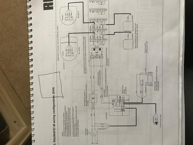
sorry, I'll try the photo again

-
So to clarify what's happening at the moment:- There is no signal connection from the controller to the boiler. The combi boiler has a bridge installed between LS and LR This means the boiler heat mode is on all the time. If no heat is being called for by the controller, the pipe valves are all closed and the hot water goes round the bypass loop and the thermostatic control in the boiler fires it up and shuts it down accordingly. The single wire feed from the control system would go to LR in the boiler
-
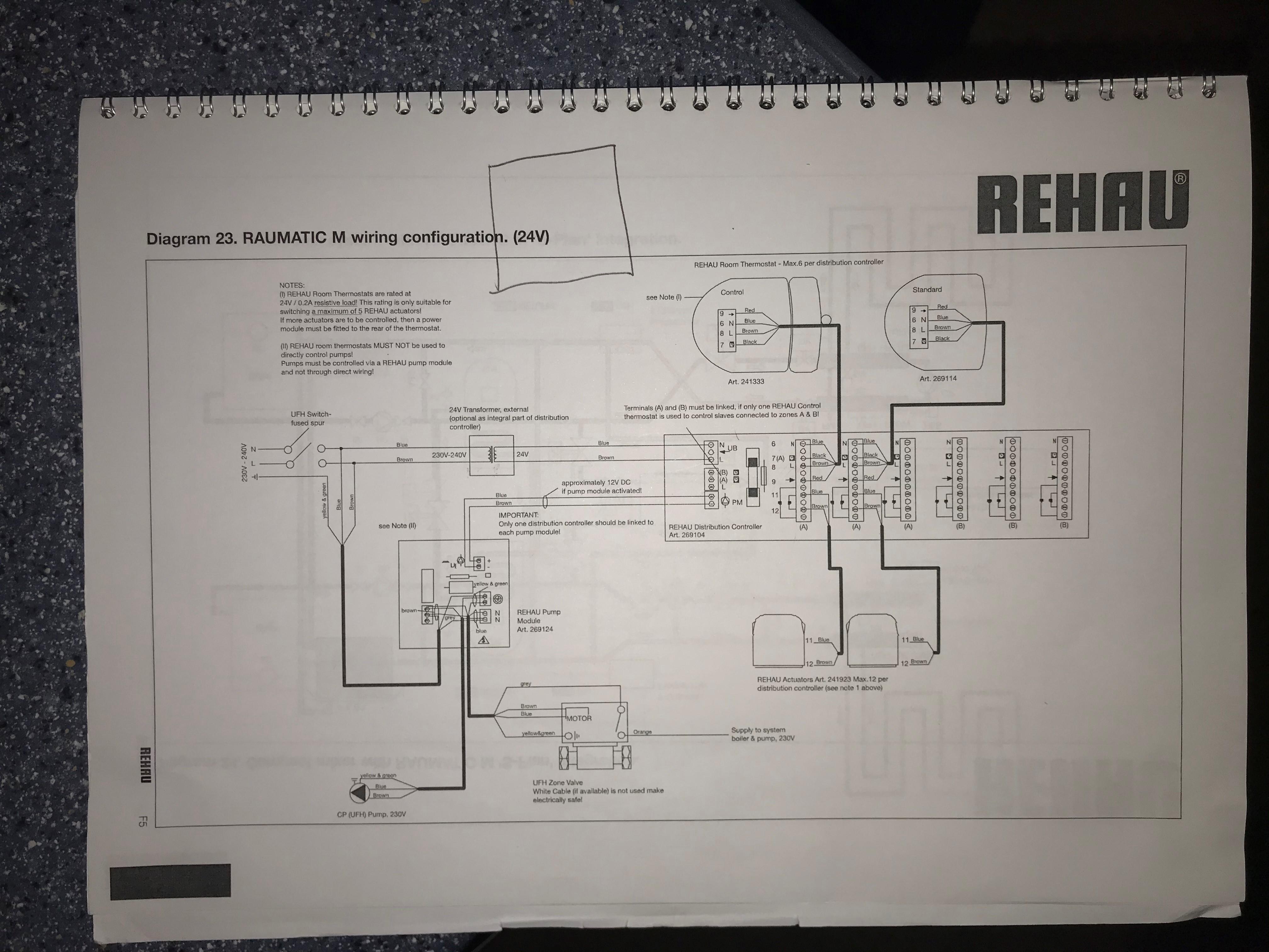
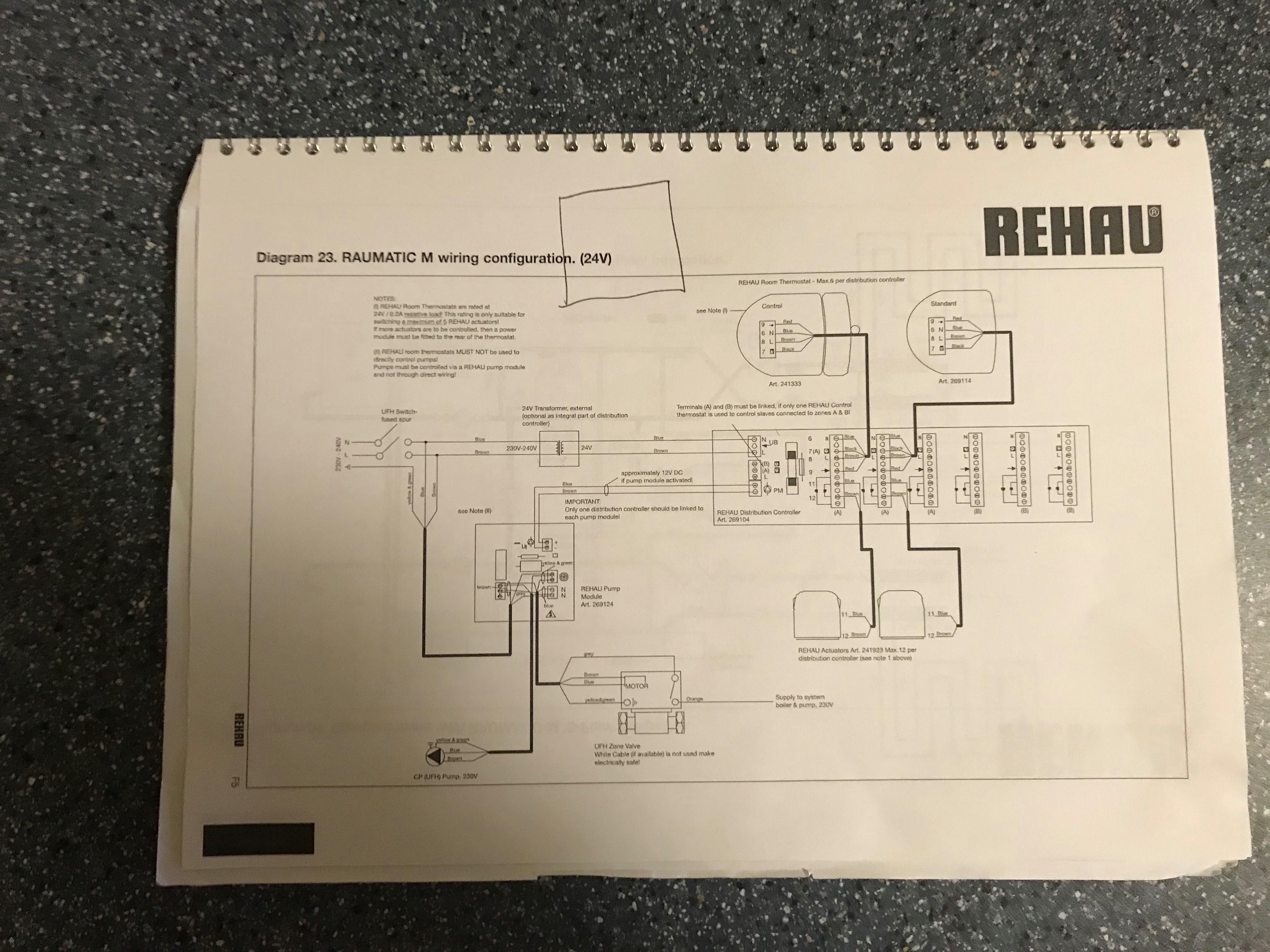
Thanks for the responses. The UFH controller switched fused spur is itself fed from the boiler switched fused spur. I've attached the wiring diagram for the UFH system. The controller is 24v. The bit we are interested in is the pump module which is effectively just a relay. The module has 240v feed (again coming from the same circuit as the boiler and the controller). This feed is switched through to the pump and to a motorized valve. When the valve is fully open a switch is triggered which then provides 240v signal to the boiler. Fiendishly clever! Anyway, it's that last bit of wiring that I was asking about - single line feed. What kind of cable to use?
-
I've moved into a property which has underfloor heating with a combi boiler. There is no "signal" feed from the heating manifold/controller to the boiler - so the boiler heating mode is just "on" all the time. The controller has the facility to connect a switched 240v live feed output which would be connected to the "LR" switched live terminal in the boiler. This would then signal the boiler to fire up only when the controller is calling for heat. So the question is what kind of wire should be used for this single feed. The manifold is some distance from the boiler and the wire could be run behind the studded wall. Is it OK to use single core wire for example with red pvc covering. Or is there such a thing as single core wire with the additional outer sheathing that is normally used with 2 or 3 core wiring? Any advice would be much appreciated