europa
-
Posts
15 -
Joined
-
Last visited
europa's Achievements
Member (3/5)
10
Reputation
-
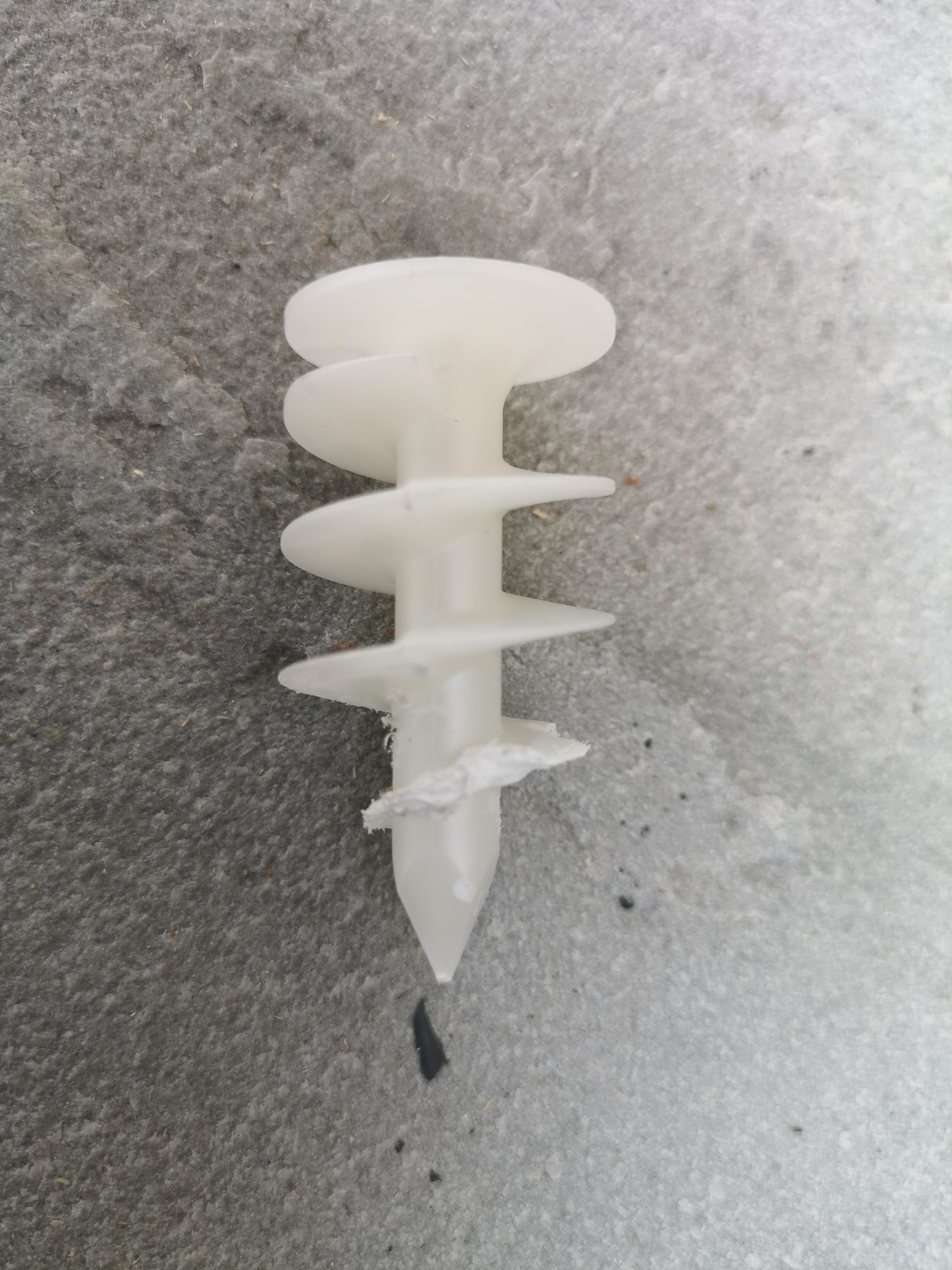
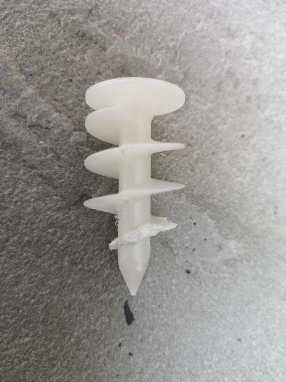
Anyone have any experience using these fixings in EWI? They are designed for exactly that, but i cannot get them to screw in thru the render. Apparently, predrilling shouldn't be necesssary with thin-render systems, but, even after predelling a 9.5mm hole, the render just eats the plastic spiral - see photo. For info., the (silicone)render should be 1.5mm thick.
-
Just a quick update. I was successful with all new (uncalibrated) actuators using the above procedure. However, i have so far been unable to recalibrate a previously-calibrated actuator. The reason i know this (and the easiest way to tell its in calibration mode) is that after the initial charging, open and close valve procedure (complete in just under 4mins from power on), there should be a long period of the actuator doing nothing - c. f. point 6 above. If, instead, the actuator reopens the valve fairly quickly (as is the case for me when trying to recalibrate), it is not in calibration mode. Clearly the instructions for recalibration are innacurate. I will have to call Salus again to find out if there is any other way to force the actuator to forget the original calibration. But if anyone has any ideas (or has successfully recalibrated one of these), do please let me know.
-
Well, it's been like watching paint dry today, but, with just one loop left, i think it's safe to say i have finally succeeded! WF did send me a new batch of actuators (and it's those that ive been using), but i don't think its that that's made the difference. I think the key is simply patience! But, for anyone who's interested, here's the procedure ive used: 1.Switch off flow to all loops. Then, attach and calibrate one actuator at a time, as below. 2. Attach the temp probes onto flow and return pipes 10cm from the manifold (as per instructions) and screw on actuators finger tight. 3. Power up actuators and the LED should then rapidly flash at ca. 4Hz (not 0.25Hz as stated in the instructions). 4. After just under two minutes, the LED will change to a slow blink and the actuator motor can be heard moving its pin to open the valve if its not already open. 5. After a short pause, the actuator motor will reverse to fully close the valve. 6. This is where the patience comes in. Next it opens the valve at tiny increments (not perceivable) to find the point of min flow in the flow pipe. This can easily take another 20+ mins, and its easy to think that the actuator is stuck, but don't give up! Eventually, the actuator will kick back into life and, with a slow flashing LED, reopen the valve fully. 7. Shortly after this it will move to stable operation and calibration will be complete. You can then switch off the actuator and it should close the valve fully. 8. To be on the safe side, i waited 40+ mins before switching off. Hope this helps others.
-
I start to wonder whether this is at least part of the problem. I'm not sure how reliable the manifold thermometers are, but the temps they show are very erratic. Often, usually at the start of calibration when the valve is closed and the HW flow has nowhere to go) the thermometer temp on the return side is higher than that on the flow side (as the flow is pushing against the return i think). But even during normal operation, my flow temp varies a lot and there is no way (that i know of) to prevent this. Out of interest, when calibrating, did you do one loop at a time (keeping all other loops closed)?
-
The pins don't seem any stiffer than the others and can easily be pushed down with a finger. Not sure it would work to calibrate on one of the good valves and then move them, as the actuators work by finding the point of min flow - this becomes the default position when higher delta T required - and, for some reason, this seems to vary on the valves. Also, the max flow rate on each loop varies, so i guess that might also have an effect. But thanks for the suggestion - worth a try if all else fails.
-
Good to know I'm not the only one with this issue! Salus tech support is pretty useless, and the call wait times are atrocious, so I'm not surprised you didn't get a reply by email. They appear to have little practical knowledge of the actuators, and could mainly only advise me to follow the instructions. However, they did imply that the instructions may not be that accurate and suggested that calibration takes far longer than the 15 mins stated in the instructions. And that does seem to be the case.
-
No, i just wired it to a plug. So, only thing it confirmed was the behaviour on calibration. WF sent me a new set of actuators, so I'm trying again from scratch. Haven't tried the three problem actuators yet, but will do so (and update) tomorrow.
-
The thought did cross my mind, but extra work so haven't tried yet. EDIT: Have now tried. I get the same rapid flashing, so have to assume that is the correct behaviour. This gives me the feeling that the issue is not the wiring centre.
-
Yes, that is quite possible as I've tried this procedure numerous times and i have never seen the claimed 0.25Hz flashing behaviour. The problem is that Salus tech support seems unable to confirm the correct behaviour, and WF tech support thinks that rapid flashing (as opposed to 0.25Hz) is actually the correct behaviour and indication of calibration! If only Salus could tell me if their instructions are right or wrong!
-
No, as i said before, i don't have standard thermostats. Instead, i use an automation system to monitor the temp in each zone and switch the wiring-centre zones on and off as required. However, for calibration/testing, i have disabled the automation and am manually switching on the relevant zones in the wiring centre. So, when i switch on a zone in the wiring centre, it powers the relevant actuator, generates boiler enable, calls for heat and switches on the pump.
-
I don't have the stats, just the wiring centre. When I power up any of the actuators, the wiring centre calls for heat continuously until i switch them all off.
-
The other thing ive noted is that the LEDs never flash at the stated 0.25 Hz (as per the instructions) at start up. Instead they flash rapidly, sth like 2-4 Hz. Salus tech support had no explanation for this. They also couldn't explain why the instructions state the temp probes should be attached 10cm from the manifold and facing forwards. This isn't poasible on the flow pipes as the actuators are too large. Salus could only say that maybe they are incompatible with the WF manifold. Yet these are the only AB actuators that WF sells!
-
Thanks. I had actually already read that thread (as i have a similar issue) and discussed it with Salus tech (which has been pretty useless). Two of my loops are quite short, and, on one of them, the Salus actuator is totally throttling the flow - closing the valve completely. The result is that the heating effect stops for quite some time - up to 20 mins - before the actuator then overcompensates and opens the valve fully. Salus tech support said that the only way for them to check the firmware is for me to send them to them. WF support said this behaviour is typical on some shorter loops. If so, then that is surely an inherent flaw in the design, and makes these actuators pretty useless in practice.
-
Here's the weird thing. WF tech support told me that the latest actuators (which i have) have been redesigned by Salus to be compatible with Heatmiser. They apparently have a lower IMAX (whatever that means!). It's worth noting that the startup sequence is pretty similar whether in calibration or non-calibration mode. That is, the led always flashes rapidly for almost two mins before anything happens. That is weird and makes it difficult to know whether they are in calibration mode or not. This behaviour and Joth's comment make me wonder whether sth is happening that causes them to go into calibration mode every time! But i can still not understand why the Heatmisers should be causing this. 230V is 230V regardless of the source, no?
-
Hi, everyone. I have a seven-port, five-zone Wundafloor UFH system, with a Heatmiser wiring centre. I've been trying to get my new Salus actuators to calibrate properly. But I'm having an total nightmare with them. The main problem is that on three of the seven loops, the actuators do not shut off the flow when powered off. The actuator pins simply do not understand how far to move. This does not happen on the other four ports. Wundafloor has kindly sent me replacements, but they have made no difference. Wundafloor thinks that the issue could be the Heatmiser wiring centre. But i don't see how. After all, it doesn't happen on all the ports and the actuators simply need 230V and the wiring centre supplies this. I'm at the point of giving up and going back to standard electric actuators. Do any of you have any ideas?