Mulberry View
-
Posts
845 -
Joined
-
Last visited
-
Days Won
1
2 Followers


Mulberry View's Achievements

Regular Member (4/5)
141
Reputation
-
UFH - Supply and Return pipes...
Mulberry View replied to Mulberry View's topic in Underfloor Heating
That's always my concern, nobody cares as much as I do, it's why I have trouble handing anything over! I know many of these things don't actually matter, but I feel better if they're done right. Plus, despite being a competent DIY'er, I've never done this stuff, it's all new to me and I'm not a "tradie". Thanks for your words, it's helpful. -
UFH - Supply and Return pipes...
Mulberry View replied to Mulberry View's topic in Underfloor Heating
How did you go about cutting them into the lower one? I have 150mm PIR already laid. My plan was to lay the supply/returns, then add the top layer of PIR around and over the pipes. It felt like it'd be easier than trying to carve channels in the already laid layer? -
UFH - Supply and Return pipes...
Mulberry View replied to Mulberry View's topic in Underfloor Heating
You didn't read what I wrote alongside that pic! LOL. Regarding the internal level changes, they are also outside, we have a tricky plot and an even trickier shaped building. They need to be inside really. -
UFH - Supply and Return pipes...
Mulberry View replied to Mulberry View's topic in Underfloor Heating
How would running these pipes around the house benefit? I can't see how it would shorten or simplify the routes unless I've missed something obvious? -
UFH - Supply and Return pipes...
Mulberry View replied to Mulberry View's topic in Underfloor Heating
This is them sketched by me on an earlier layout plan. Ignore the pipe layout and manifold positions on that plan, this was an overlay to show my proposed position of the M1 manifold and the omission of the M2 manifold in the middle, along with routing of the supply/returns. Where the omitted manifold is shown there, the supply/returns need to turn up out of the lower floor, ascend by 600mm then turn back into the Kitchen floor. The 600mm vertical section will need to be contained in a battened out wall.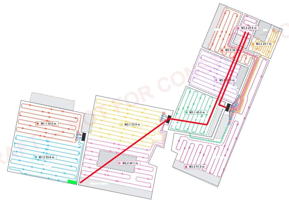
-
UFH - Supply and Return pipes...
Mulberry View replied to Mulberry View's topic in Underfloor Heating
The insulation thing intrigued me too. I asked AI, which told me that PIR is great at stopping heat from travelling downwards, but isn't so good at preventing it travelling sideways through the PIR boards and that the sleeving on the MLCP pipes somehow performs differently! Who knows. Not me that's for sure. I do know that I have to be able to create 90° bends halfway along the pipes, to transition as needed without fittings. -
UFH - Supply and Return pipes...
Mulberry View replied to Mulberry View's topic in Underfloor Heating
So, back to the original point, Supply and Return pipes to/from the manifolds. What type of pipe is best to use here? I'm installing 25mm (26mm?) that will be within the PIR, with 150mm PIR under it. There is about 30m of linear length to reach both manifolds, so I'll need 60m of pipe in total, which I understand needs to be insulated despite it being installed into PIR? Is it just 25mm Pre-insulated MLCP? As for the design, the designer was certain that 300mm spacing would meet the heating requirements, but I've had him do 200m spacing to be on the safe side (150mm in the Bathroom). I don't really ever want to do this again and certainly don't want to have to use plug-in heaters if it gets chilly! There are 2 manifolds as this simplified the routing. The M3 manifold is at the lowest ground floor level, the M1 manifold is 1m higher in terms of ground floor FFL. The bundle of pipes running along the hallway to the WC and Utility will be in conduit as they are just transit pipes and the heat they emit is not required before the rooms. This design saves 400m of pipe compared to the earlier designs. The ASHP will be against the wall in the top-right of this drawing, so the manifold connections are the hardest part here really.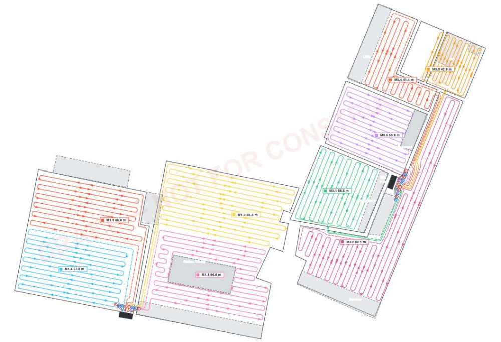
-
EPDM DPM to DPC - How best to complete....?
Mulberry View replied to Mulberry View's topic in Damp & DPCs
Of my 3 external doors, 2 of them are under significant "canopies" and one is on the North side in a very "unexposed" position. That doesn't lessen the quality I wish to achieve in the detailing, but the 2 sheltered doors will definitely never see much in the way of direct rain or snow. Thanks for your help everyone and onto the next. 🤣 -
EPDM DPM to DPC - How best to complete....?
Mulberry View replied to Mulberry View's topic in Damp & DPCs
-
EPDM DPM to DPC - How best to complete....?
Mulberry View replied to Mulberry View's topic in Damp & DPCs
I'm thinking of laying the upstand flap of the internal 1200ga membrane over onto the flat light blue XPS face, then laying the EPDM from the door threshold over the top of it and bonding the 2 together on the horizontal plane, or vice versa. This is a rough diagram of what I propose. The magenta is the EPDM, the green is the 1200ga DPM. I hope it's not too hard to see... I wouldn't be able to retain the turned up portions of the EPDM on the jambs if I want it to head downwards, but are they really doing anything? I could triangle cut them to allow the EPDM to fold down. Does a threshold DPM usually turn up the jambs anyway? Apologies that this sketch is not at all in proportion!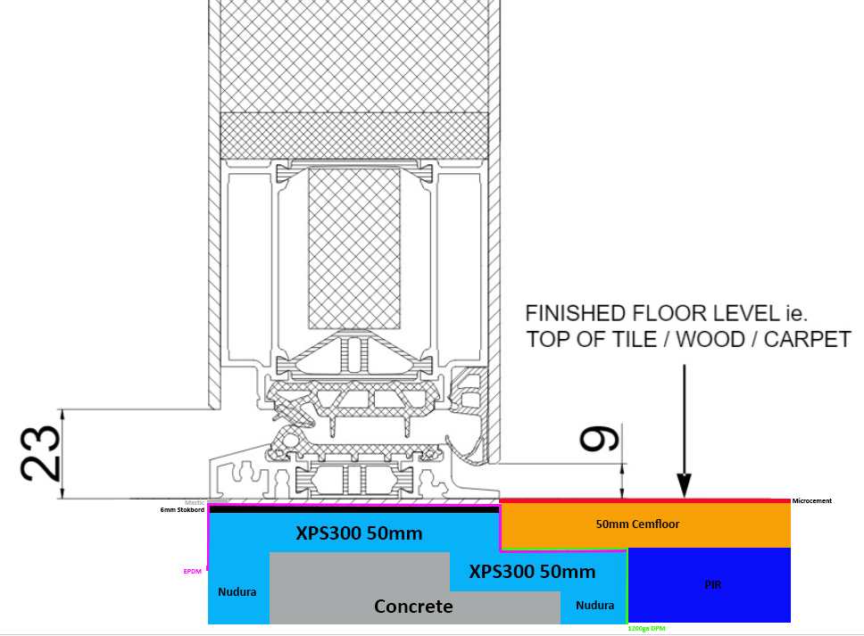
-
EPDM DPM to DPC - How best to complete....?
Mulberry View replied to Mulberry View's topic in Damp & DPCs
The RK door is set up for 9mm clearance. You can see the skimpiness of the threshold arrangement in that drawing. Essentially, my EPDM sits on the datum line where the arrow points and just has slim packers (around 5mm) between it and the underside of the threshold.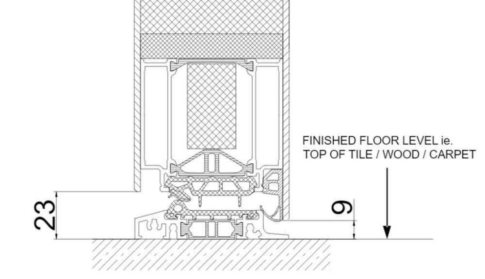
-
UFH - Supply and Return pipes...
Mulberry View replied to Mulberry View's topic in Underfloor Heating
I've just received the first draft of a more thought-out UFH layout. The designer has gone for 300mm pipe centres. It looks (worryingly) simple! I've raised concern about heat striping, I don't really want to risk that. He has gone for 3 manifolds, one on each of the 3 ground floor levels. 2no 2-port manifolds and 1no 6-port. I've proposed and idea for 2 manifolds and have fed that back. He has suggested that 20mm MLCP for each manifold is sufficient, something I've probed on because it seems very small. I'll share the design once I have it, but I am minded to want closer pipe spacing as I'd prefer some headroom. Not least in case I can't hit my desired ACH. I'd rather have more pipe and have to control the flow temp than find it's just weak performing. -
EPDM DPM to DPC - How best to complete....?
Mulberry View replied to Mulberry View's topic in Damp & DPCs
Inward. -
EPDM DPM to DPC - How best to complete....?
Mulberry View replied to Mulberry View's topic in Damp & DPCs
So, I'm lapping the EPDM with the lower DPM that runs under the PIR as opposed to the slip membrane that'll go over the PIR? -
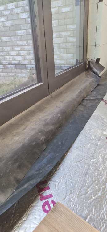
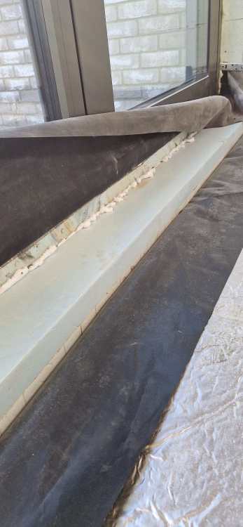
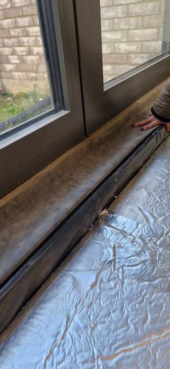
This is an external door installed onto XPS with EPDM as the DPM. The EPDM was left long on the inside. I turned it up at the sides in case it was needed. It's an ICF build with Waterproof concrete and no conventional DPC. It's an RK door with a skimpy low threshold, almost non existent upstand. The floor is Block & Beam, there is a 1200ga DPM under the PIR, this is what you can see in the image laying back onto the PIR. This is with the EPDM lifted. The inner threshold is 50mm below the door threshold, but still XPS. The screed needs to come up almost to the underside of the threshold, with 3-4mm Microcement as the final finish. How should this detail be finalised? Should these membranes just be taped together? Any expansion joint along the threshold? There's another 80mm of PIR to go on yet, this will bring it level with the blue XPS, with everything 50mm below final FFL. I have 2 more Norrsken doors following roughly the same principle. As always, your help is invaluable to me, and I'm procrastinating on it at the moment!