glenboy
-
Posts
8 -
Joined
-
Last visited
glenboy's Achievements
New Member (2/5)
1
Reputation
-
Moving a manhole for an extension add on
glenboy replied to OldieNewbie's topic in House Extensions & Conservatories
Hi, I just saw your post. This may help. -
building a timber frame first floor over a cavity wall
glenboy replied to Rdddk's topic in Timber Frame
Thanks for your replies on this. As this has had over 6000 views so far it means that its of interest to a lot of people. I am guessing by looking at the drawings etc....its a case of up to whoever is building it. Both/most ways will work. Inner and outer are to some extent connected by catnic and steels with plate welded on bottom. Some sort of cavity closer/Dpc just in case of any damp from wall below. I guess the dpc if it was bedded on the external leaf would allow a bit of movement. The inner being strapped and with existing top plate will help to fix the new timber spanning both inner and outer leaf So put insulation in yellow. The existing timber wall plate in green and along the bit between the joist the box section of timber the odd bit of timber down the run as noggins. The Front wall I would guess you do the same.... as per my other drawings above slightly adapted.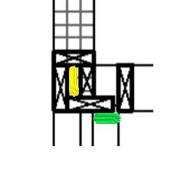
-
building a timber frame first floor over a cavity wall
glenboy replied to Rdddk's topic in Timber Frame
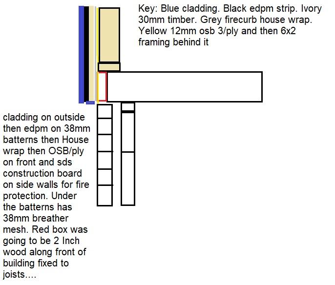
@Russell griffiths @Simplysimon Thanks for your input.....this is what I have for the side walls.....for the guy who drew the plans... This is looking from the front and with one of the joists....the left wall rests over the cavity as can be seen in this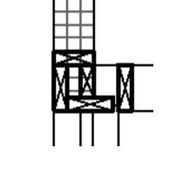
-
building a timber frame first floor over a cavity wall
glenboy replied to Rdddk's topic in Timber Frame
Well it is first floor and the cedral click ask for the edpm to run upto the top of the batterns which I think are 38mm deep by 100mm wideand the edpm is fixed to that. Yep it is going on the current flat roof extension to 2 storey. Yep the foundations are up to it as I dug them out. I think from memory its 1.5 meters deep there. Other option I can only think of would be this...... maybe have another block between the joists. Celotex at the front and the knuff wall behind the block. An the pink panther insulation is in the 50mm cavity below
-
building a timber frame first floor over a cavity wall
glenboy replied to Rdddk's topic in Timber Frame
@Simplysimon yeah its 7x2 timber floor joist. which at the moment are over hanging the outer leaf. with a facia and sofit in wood. Here are a couple of drawings of what I have now and what I am sort of looking at doing...but maybe stick some dpc under it.... yeah timber floor with chicken wire and insulation between it.... Cedral click cladding by the way...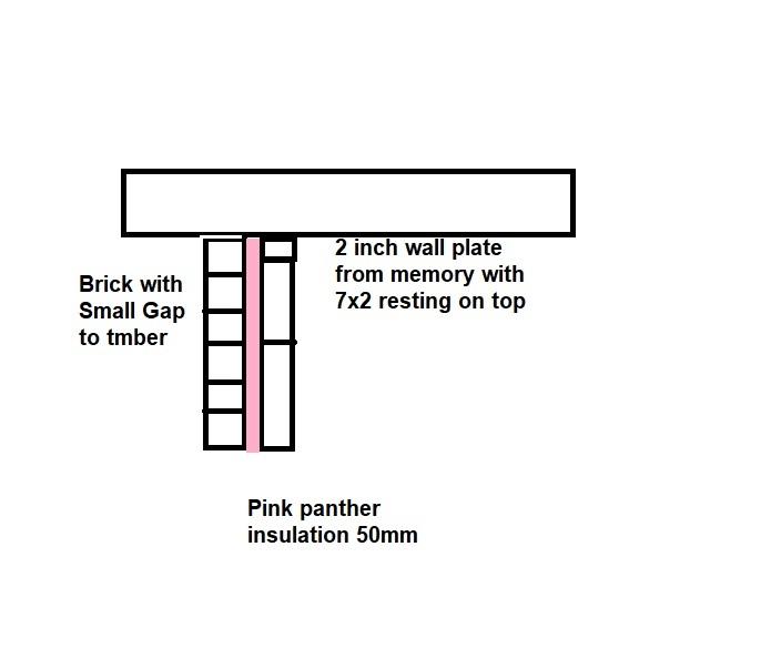
-
building a timber frame first floor over a cavity wall
glenboy replied to Rdddk's topic in Timber Frame
Any idea why no one ever replied to this? I have to do something quite like this.......I have a 50mm cavity wall and was going to roll a bit of dpc under the timbers from the inner leaf and stapple it down the side of the top plate and roll it up the front of the osb on the front.....other option was to close the cavity with a normal cavity closer and stick some dpc on top of that and take it out the front. Thanks for any input. -
3 timbers on top of timber frame wall?
glenboy replied to glenboy's topic in RSJs, Lintels & Steelwork
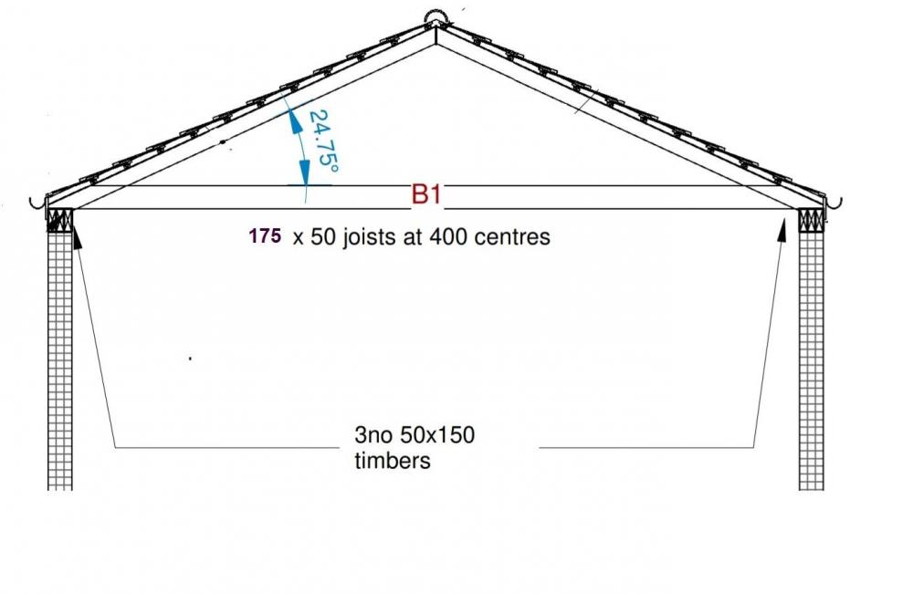
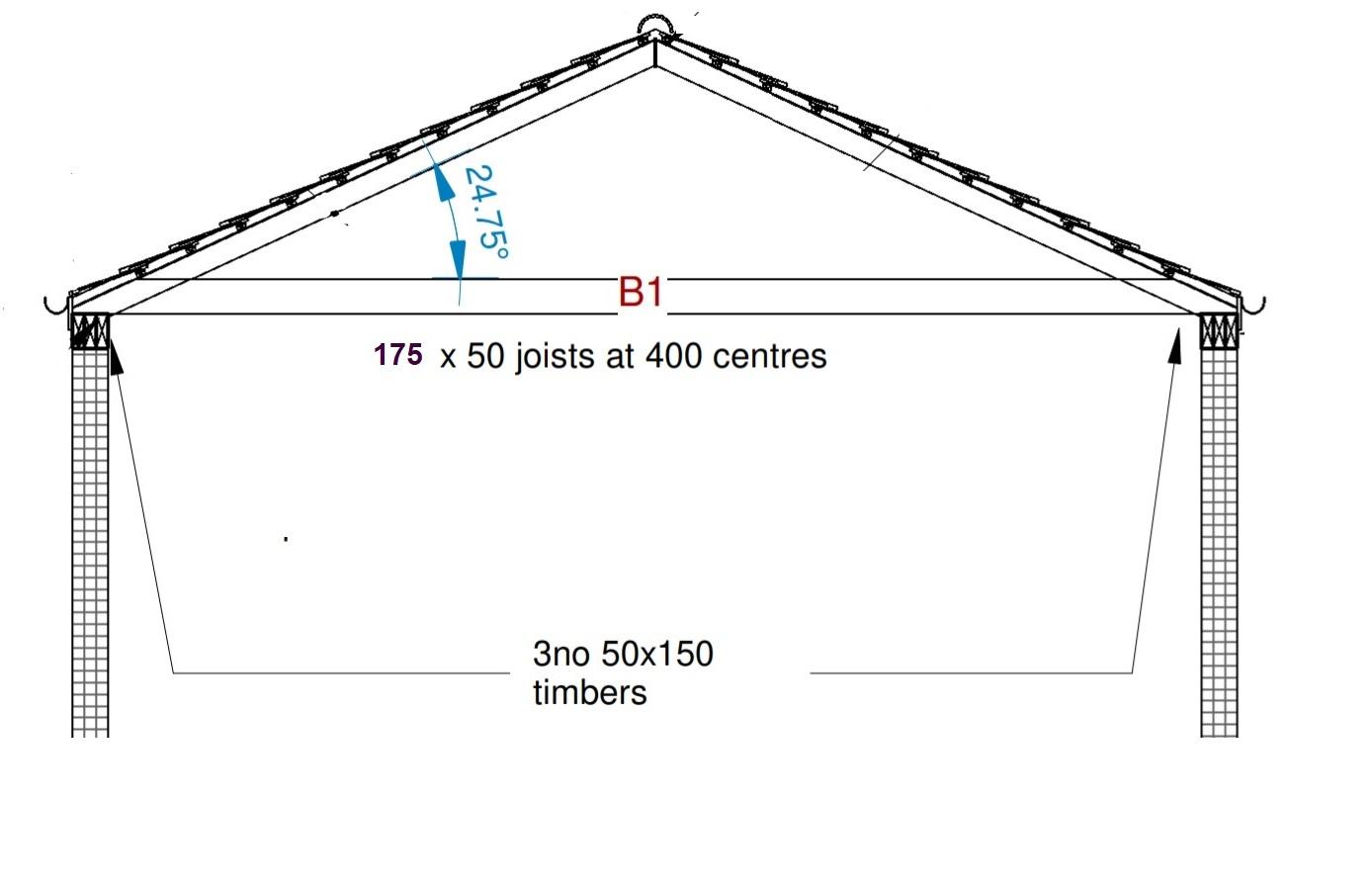
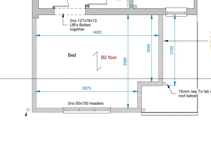
Thanks for the other guys replies. @Gus Potter thanks. There is only 1 window in the front I will post a bit more of the plan. A couple of questions. I take it you would coach bolt the 3 timbers together maybe at 400 centres staggered? Also how would you fix these to the 150 vertical wall studs. Would you drive a long screw down through the 150 high timbers into the wall studs or metal strap them. I guess we cannot use the nail gun to gun in at an angle. Also how would you tie the front aspect timber wall into these side walls? as we cant use the plate overlap method? Once again thanks for your guys replies. Thanks
-
Hi there, I'm not sure if this is posted in the correct section or if I need to post it in the timber frame section. My question regards the 3 no 150 x 50 timbers which seem to be vertical in the drawing at the top of the walls. This is a first floor timber frame extension on top of an existing brick and block wall. Reason for timber frame is the cavity is only 50mm. So has to be done this way for U value. Is it normal for the timbers this way Vertically as I have normally on all the programs and books is Horizontal and the timbers overlapped at the corners. The wall studs are 400 centres as well. Thanks