connick159
-
Posts
108 -
Joined
-
Last visited
Everything posted by connick159
-
You wouldn't have a pic of where the uh8 cable comes into IN1 on the ecodon FTC would you. I suspect my sparky has stuffed it up as my uh8 heat enable feed is not connected at all to the IN1 block. I think I need to connect the live and live switch to the block but not 100% sure. Thanks for the post and glad your problem is solved. Be good to hear how the remote option worked out as I'm considering the same. I have all heatmiser stats in rooms hardwired back to 2 uh8 (one in the front of house, one in back). If what you have done works well for you it'll likely be a good option for us too.
-
Ok, so I looked at the FTC6 now and have found the 2 cables (heat enable) from each of the UH8 controllers. What I have found is that they are both wired into the L/N/E block but nothing at all into any of the input terminal blocks. Given that, I dunno how this is working but it seems to be, just doesn't seem like its working right but... The stats call for heat, the heat pump sends the hot water to the manifolds but how? And could this also be the reason for the erratic flow temps?
-
Connecting heat enable to Mitsubishi Ecodan
connick159 replied to Scotland's topic in Air Source Heat Pumps (ASHP)
Thanks for this post. Its really helped! What if you had 2 UH8 wiring centres, one in front of the house and another for a new extension at the back of the house. Each with their own manifolds. How could you connect up the 2nd UH8 back to the FTC6? -
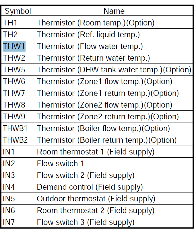
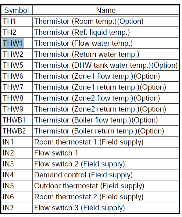
I was looking at the 'Thermister Reading' page. It was the THW1 which was set for the flow temp.
-
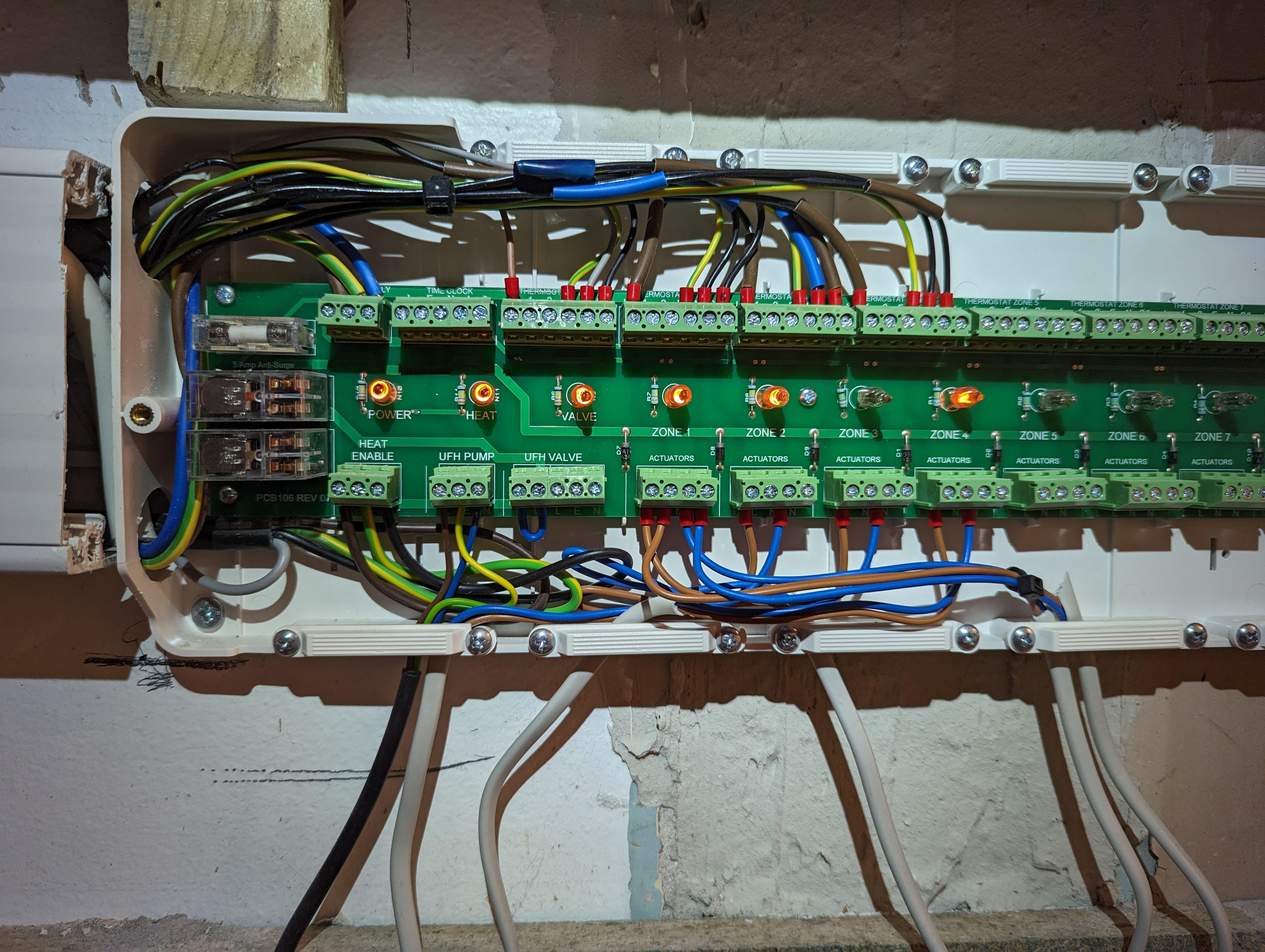
Here is a pic of the ufh8 wiring in area 2. All looks ok. no valve on this 2nd manifold hence the loop 'UFH Valve" I'll have to check FTC6 as suggested. I've opened it but bamboozled by all the switches etc. Will try and read some diagrams or instruction to find out where the 'heat enable' from this 2nd UFH8 controller should connect to on the Ecodan FTC6. @simonD - any pointers for where to look in FTC6 first? Thanks again.

-
Thanks Simon, It seems to work ok when area 1's calling for heat. It's only the 2nd heatmiser unit that it happens on. Good shout re the hotwater but we have that set at only 43 degrees and its on a timer to come on at 4am to 6:30am. The only time it would go to 60 is doing a legionella cycle which would need the immersion heater to get it up to that. I'll take a look at the 2nd heatmiser wiring centre and maybe post a pic.
-
Hi all, I'm struggling to get hold of the ASHP mob and sparky who did the initial installs but suspect there is a problem coming from the second UFH8 (heatmiser controller) which is located by the second manifold and controlled by Heat miser room stats. To help me try to explain... Lets call the new extension "area 1" and the old cottage "area 2". Both areas have an UFH manifold each. Both areas have a heatmiser UFH8 wiring centre each and, both have several room stats connected back to their respective UFH8 wiring centres. The UFH8 wiring centres are then both connected back to the Mitsubishi ecodan FTC6 controller. Ecodan ASHP is set to Weather Comp to control the flow temps. Problems: When "area 2's" stats call for heat, the wiring centre in that area lights up for the correct room calling for heat but, when i go back to the FTC6 controller, the heating icon still has the 'Paused' symbol displayed just like when there is no heating being requested at all. At the same time, the flow pipes on area 2's manifold are hot. Sometimes way too hot. Today, the flow temp hit 60 degrees even though weather comp is set to a max of 40. If i force area 1 heating on by turning up a room stat then the heating icon on the ecodan changes from Paused to Play symbol. I'm really at a loss here and can't work out why: a) the call for heat in Area2 is not making the ecodan heating activate (from paused to play) b) How the hell can the flow temp go to 60 deg if Weather Comp is set to a max of 40 at -3 deg outside. Any thoughts / tips /pointers would be very much appreciated. Thanks
-
new wiring, all sockets tripping charging a phone !?
connick159 replied to connick159's topic in Consumer Units, RCDs, MCBOs
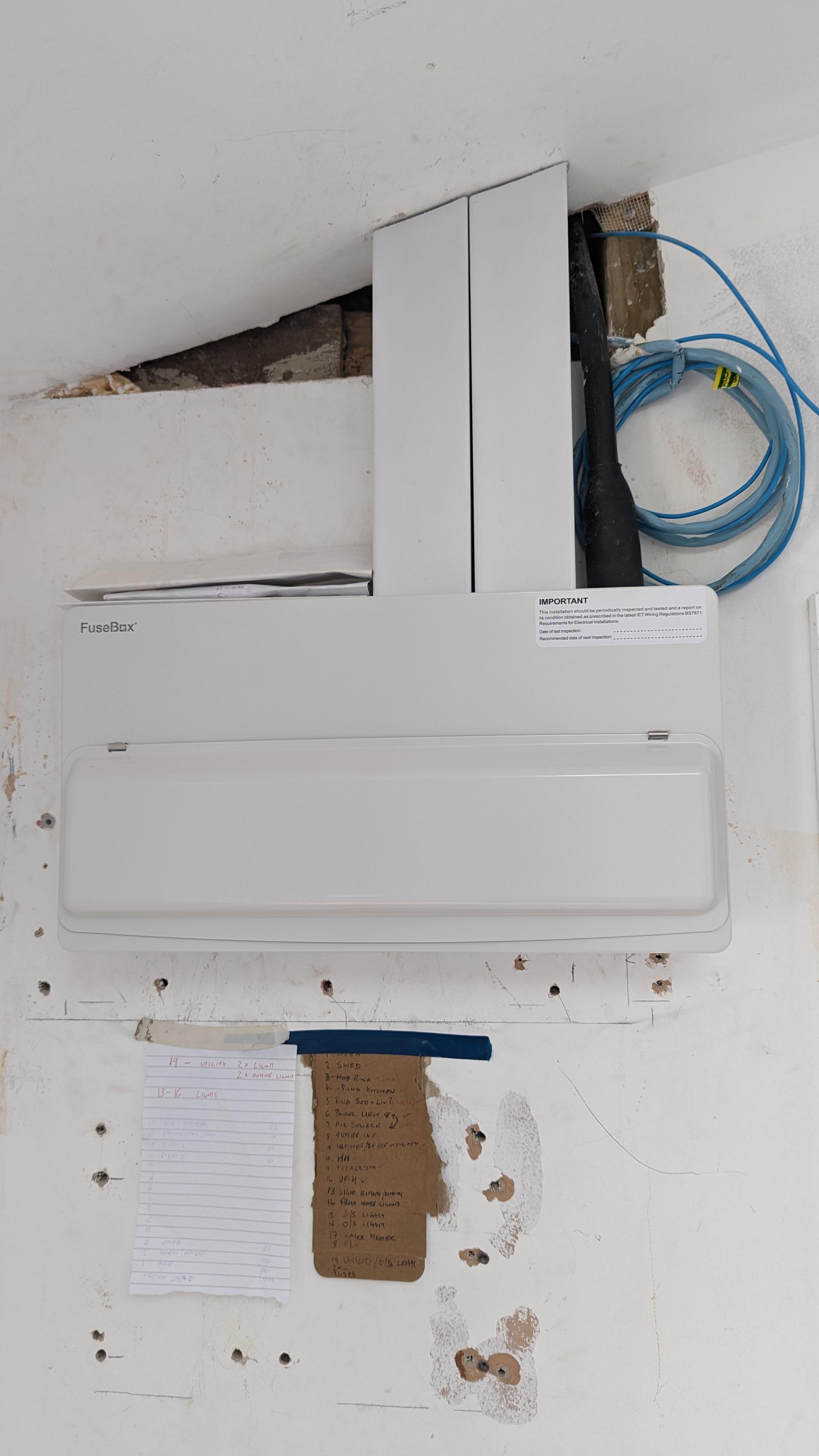
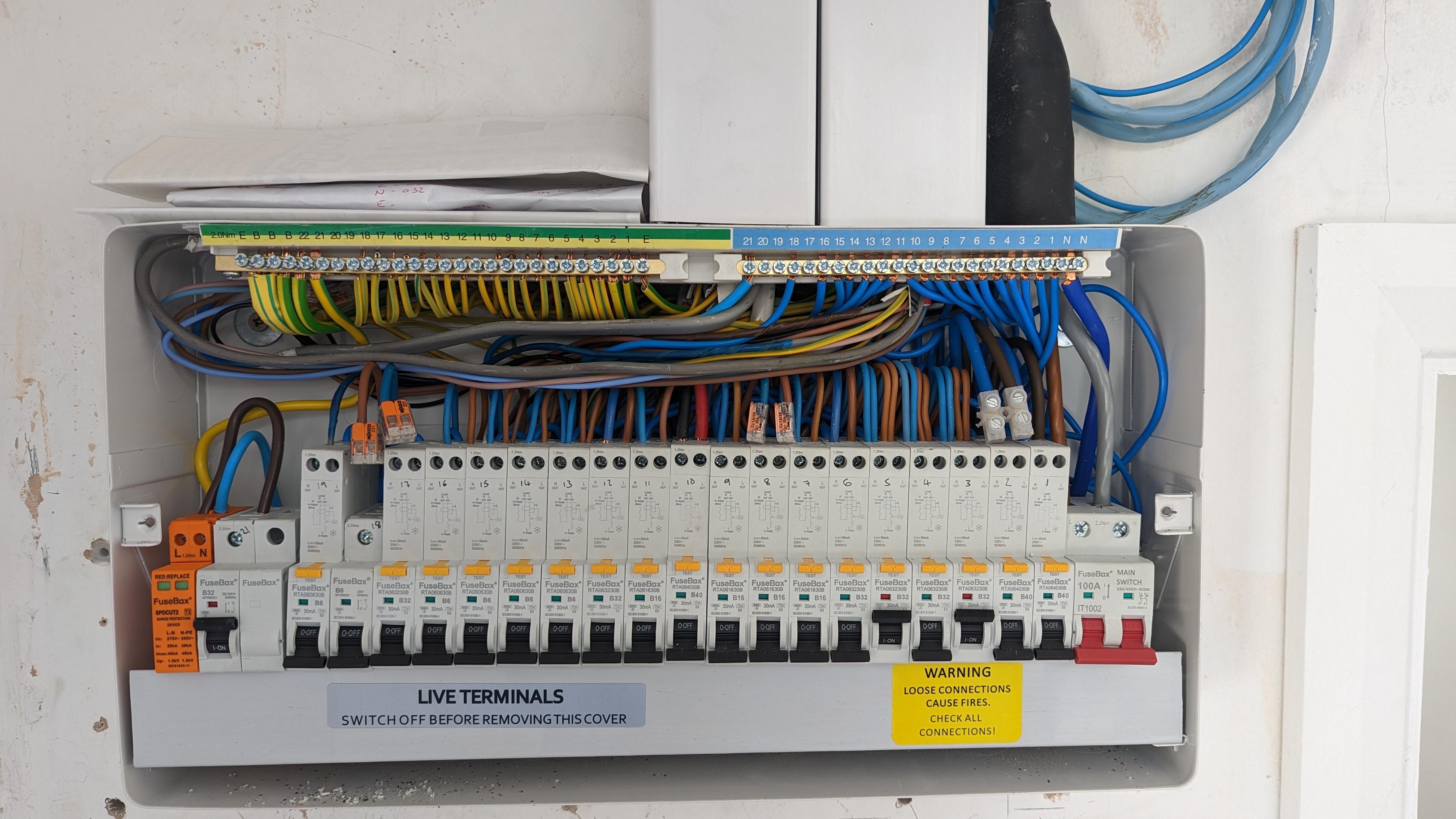
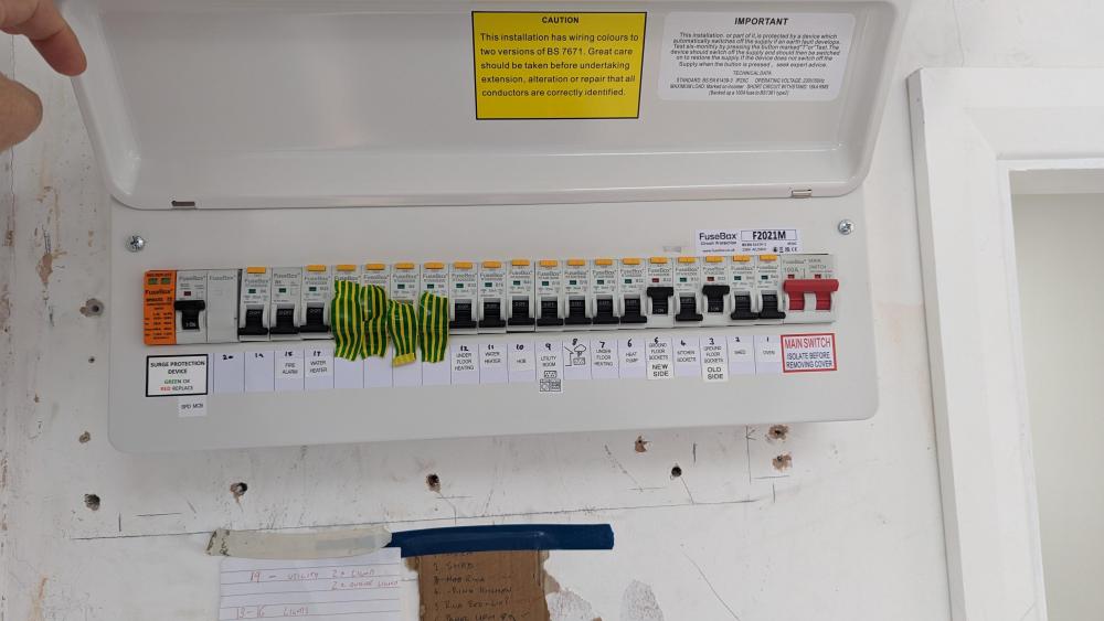
Update: Unfortunately they couldn't finish all the testing as a fair few junction boxes in attic still need finishing and boxing off but they tested what they can and everything has passed except lighting (due to attic work required) and kitchen sockets due to an "earth continuity fault". They asked for the other guy to finish the JBs in the attic and fix the earth fault and they'll return next week to finish up and test the rest as they are working away from tomorrow. Here are a few of the latest pics. The before and afters are amazing when I look at them side by side!

-
new wiring, all sockets tripping charging a phone !?
connick159 replied to connick159's topic in Consumer Units, RCDs, MCBOs
They went and got new gear and started fresh. A lot of the day was spent ripping out, reading the notes and labels from other guy but also doing work on the incoming feed. I wasn't there except to let them in but I think, apart from some preliminary testing earlier today, most of their testing is in for tomorrow. But he did say that there are a lot of junction boxes been used up in the attic/ceiling which they thought unnecessary. Some of which still seem to need completing so unlikely he'll be able to sign everything off by cob tomorrow. -
new wiring, all sockets tripping charging a phone !?
connick159 replied to connick159's topic in Consumer Units, RCDs, MCBOs
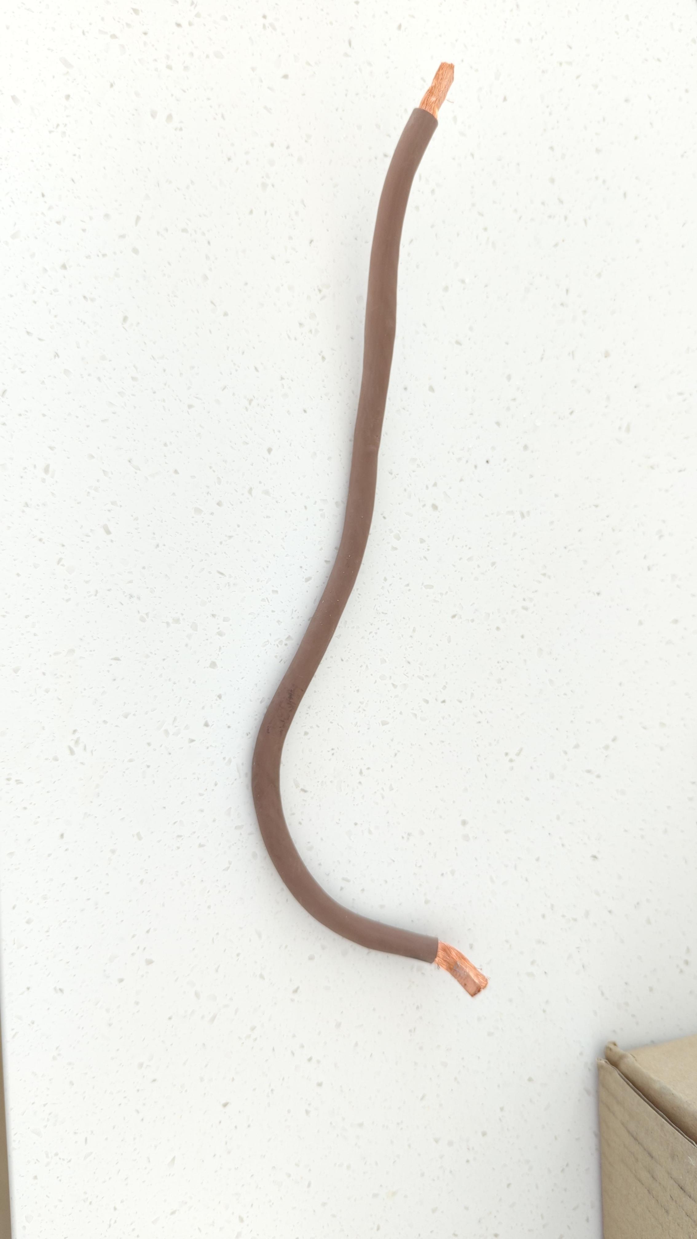
Hi all, Just updating. New sparks came in today. Ripped it out and started again. Also added a new isolation switch and SPD on the feed into the armoured cable near the meter coming in. Back tomorrow to finish off. Thanks again for all the advice. Been a £1100 lesson but I appreciate all the feedback from you all. Cheers.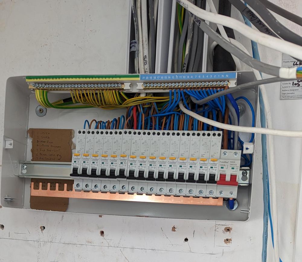
-
new wiring, all sockets tripping charging a phone !?
connick159 replied to connick159's topic in Consumer Units, RCDs, MCBOs
What's the requirements for surge protectors? Mine do not have any but I've seen them on Hager website and now unsure if they are required by regs? If so, and each cu gets separate feeds as per the Henley block suggestions, would I need 1 in each cu? -
new wiring, all sockets tripping charging a phone !?
connick159 replied to connick159's topic in Consumer Units, RCDs, MCBOs
Yeah, thinking of splitting the armoured via one of those junction boxes (Henley block) I think they are also called. One.eqch for the N and L feeds and then sending one to top CU and then other to bottom CU. Then the rest as you say sorting out the config of circuits in the top CU and RCD (or RCCB) in the bottom. Thanks again all. -
new wiring, all sockets tripping charging a phone !?
connick159 replied to connick159's topic in Consumer Units, RCDs, MCBOs
Update: he's not back till Sunday so while main fuse was out a swapped things around. Took out some mcbs and re did the way the RCDs were connected based on advice here. (Just top CU at this stage.) I put the lighting and socket circuits on the RCD as well as oven and hob. Put main fuse back in then turned it all on. Sockets and lighting both work without any trips like before. Result! There was a neutral being crossed from what I could see so once each RCD was on separate N bars prob resolved (I think) Will leave it there but thanks for all the help. Next challenge is having the WTF conversation on Sunday. New bloke coming for a look on Tuesday. Will give an update then for anyone interested. Cheers -
new wiring, all sockets tripping charging a phone !?
connick159 replied to connick159's topic in Consumer Units, RCDs, MCBOs
Aren't those pics of the dual rail CUs just the same as what I have had Frankensteined together? I.e. 2 din rails that need L and N transferred from 1 to the next? I know they are two separate cu enclosures but would then logical connection not be the same as the dual row in the link before? -
new wiring, all sockets tripping charging a phone !?
connick159 replied to connick159's topic in Consumer Units, RCDs, MCBOs
Ah yeah, got that. I meant to join the top cu and the bottom one. At the moment he has the live from the armour going into the main switch and "daisy chained" I guess you could call it straight down to the Main switch in the bottom cu (see pic). What I think you are saying is to use the 2 prong busbar to join then main switch in the top to the rcb next to to it. But... From that rcb (or was it mcb) do you then run a cable down to the lower cu so can do away with that "daisy chain" set up out of the top cu's main switch to the bottom cu main switch. He's coming back tomorrow arvo so gunna be an interesting chat. Thanks again. Sorry for all the questions. Must be annoying but I do appreciate the shared knowledge here.
-
new wiring, all sockets tripping charging a phone !?
connick159 replied to connick159's topic in Consumer Units, RCDs, MCBOs
Thanks Dave. Great info! L jumper... Is it one of these?
-
new wiring, all sockets tripping charging a phone !?
connick159 replied to connick159's topic in Consumer Units, RCDs, MCBOs
sorry but can you give more info on what an L jumper is? Also, in the link above to the Hager high integrity unit, it seems to have the main switch down the bottom row so I assume then power from the armoured cable would have to go to that one first. Not sure how it would reach to that incoming point as looks to be already cut for top board and won't reach. Perhaps just reverse the pic and have the main switch and surge protector up top? Thanks again. still planning on getting some one else in but as I've come this far I now want to know these things. Wish I was still ignorant to it all as that would mean the job was done and we'd fully moved in! -
new wiring, all sockets tripping charging a phone !?
connick159 replied to connick159's topic in Consumer Units, RCDs, MCBOs
Something like this you mean? https://www.cef.co.uk/catalogue/products/4780707-10-14-dual-row-dual-rcd-high-integrity-metal-clad-consumer-unit-with-spd?gclid=CjwKCAjwx_eiBhBGEiwA15gLN1B9KDl4I_EtiEt87vcTFCDU1e_1h0pahuWpq-aWnoGrbOvtP0dfSxoCCtkQAvD_BwE&gclsrc=aw.ds Would you then also use rcbos as well? -
new wiring, all sockets tripping charging a phone !?
connick159 replied to connick159's topic in Consumer Units, RCDs, MCBOs
i see what you mean. thanks. Would that MCB need to be right at the end of the line in the top board and then give the live into the main switch of the bottom board? I've confirmed another co to come next Tuesday but the fear is they then tell me they can do it but are booked solid for 2 months. I've told my mate I want the armored coming into the CU on the RH side so that everything can then go back to the default setup that the box actually ships with. i.e. the main switch on the RH side. -
new wiring, all sockets tripping charging a phone !?
connick159 replied to connick159's topic in Consumer Units, RCDs, MCBOs
I've called someone else and they are coming to look next Tuesday and give me a price. Pulled the main fuse too actually and stripped out half of the board. I've also told my mate that i'd like everything to stop until the board is sorted. It's been tough and is pretty stressful. I can see how much money I've also wasted on these boards and the gear but, i think at this point, I call it a day with him and have beers with him instead of asking him to continue. I'll then go and punch my other mate in the head who told me to use him. Out of interest, am i out thousands for a double-decker board and rcbo's or is it more like high hundreds? Does anyone know? Hager seems expensive stuff so hate to have to bin it all. ah well, lesson learned. -
new wiring, all sockets tripping charging a phone !?
connick159 replied to connick159's topic in Consumer Units, RCDs, MCBOs
I think so. He works for one of the big sparky mobs round here anyway. Has done work for other mates too. But, this may be a bridge too far. -
new wiring, all sockets tripping charging a phone !?
connick159 replied to connick159's topic in Consumer Units, RCDs, MCBOs
Is looping the feed from the top a "big no no"? What is a better way. To put some kind of link or splice onto the main armoured and having that go into an isolator on the bottom board? I think there was RCD's on the bottom but he's moved some of the circuits originally on the top cu down in order to troubleshoot/test and has taken out the rcd's. Again, I'm not 100% sure though. I'll ask. The plan originally was to have main house in top CU and then things like the ashp, garage, outside lights and power, ufh controllers on the bottom. 🤷 -
new wiring, all sockets tripping charging a phone !?
connick159 replied to connick159's topic in Consumer Units, RCDs, MCBOs
I'm pretty sure you've hit the nail on the head. An armoured cable brings the feed in from the main fuse and it was put in first I think from memory. The cu then came in and I think he swapped it around as the armoured was on the left. Tbh though, I'm not 100% sure as I was happy to finally be able to outsource a job rather than do it myself so kind of switched off and left them to it. Thanks for all the help. I think I will pull the main fuse, move that N cable and run the mobile phone charger test again. -
new wiring, all sockets tripping charging a phone !?
connick159 replied to connick159's topic in Consumer Units, RCDs, MCBOs
what do you guys reckon would be a reasonable ETA for someone to tear down and redo the consumer units? I'm thinking of getting a label maker, asking my mate for that cuppa, telling him i'm gunna get someone else in to finish off, and then asking him for help in labeling all the cables coming into the CU's with the label maker. They have marker labeling but it's a bit like reading a doctor's prescription so, if we get them label printed it may make it a bit easier for someone new coming in. -
new wiring, all sockets tripping charging a phone !?
connick159 replied to connick159's topic in Consumer Units, RCDs, MCBOs
He did have a large tester around his neck with some prongs and I've seen him using those. No idea what they are. Look more like an expensive multimeter thing rather than one of those Megha testers I've seen on some YouTube videos.