NIMAN
Members-
Posts
18 -
Joined
-
Last visited
Personal Information
-
Location
UK
Recent Profile Visitors
The recent visitors block is disabled and is not being shown to other users.
NIMAN's Achievements

Member (3/5)
0
Reputation
-
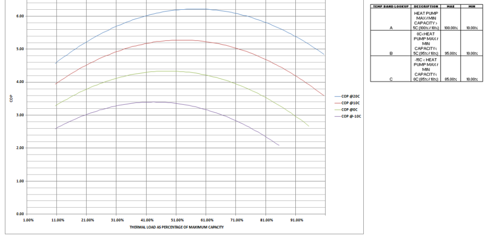
The quadratic developed from the empirical study was based on normalised figures - the machines used had different absolute figures. %'s are then, of course, the opposite of misleading (since the Physics appered to be very similar across the sample). Based on my observation of the normalised experimental figures, I chose, for now, to limit the lowest outputs to 10% and use a relatively blunt 3 band external temperature lookup table for the maximum outputs. This is an example graph of my spreadsheet quadratic developed from the empirical study of (COP v THERMAL LOAD AS A PERCENTAGE OF MAXIMUM CAPACITY) at 4 external temperatures: (The empirical study was carried out at an internal temperature of 21C - I asked the Author for permission to share the link some time ago but have received no reply)
-
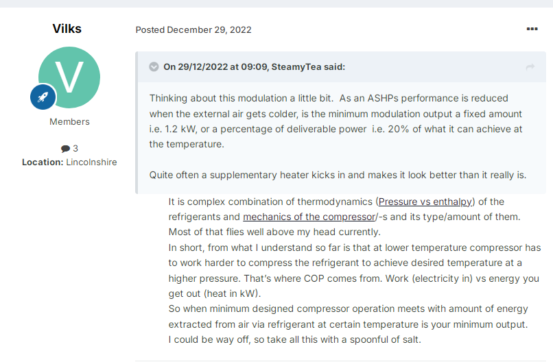
For the record, related to this comment: The smallish sample of mini-splits involved in the empirical investigation demonstrated lowest output (at lowest external temprature) at around 10% of maximum output (at the highest external temperature at which that highest output was acheieved) i.e. effectively a fixed amount. My spreadsheet model also, currently, uses this fixed 10% to calculate lowest steady state modulated output.
-
True, but even they are, mostly, somewhat calculated - even if it is only by one of the couple 😄
-
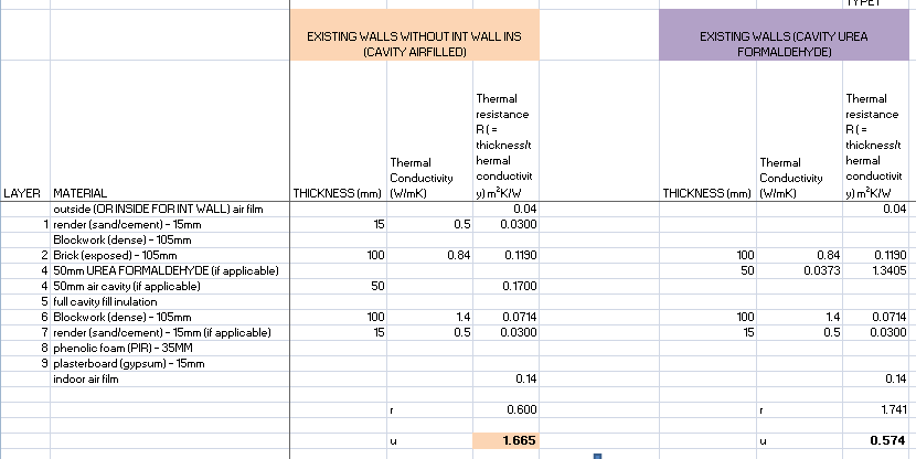
Oops, newbie here - sorry about that!! You must be younger and/or richer than me but that wouldn't be difficult. We used to have large icicles on the inside of the windows at times. The hourly spreadsheet heat loss / cop calculator (based on the emprical study quadratic) is setup as 2 zones with a dividing concrete block wall currently set at 65W/K. Intenal heat transfer between the zones is also accounted for if wishing to investigate different target temperatures in each - I am contemplating internal wall insulation on the internal divider to reduce it to 13W/K in order to maintain 21C / 10C zones with a log burner in the cold one to make it comfy on the odd party night. It'd save a fortune in running costs but simultaneusly massively undersize / oversize the 2 heatpumps compared to 21C single zone throughout. I've attached, as an example, my current 1958 external wall buildup calculation. Without the hole ridden Urea Formaldehyde cavity insulation U is 1.665 and. Before the insulation crumbled it seems like it could have been 0.574. If you have any idea if that could now be somewhere in between the 2 figures or, perhaps, worse now than when it was a clear ventilated cavity it'd be nice to know. Millions live in leaky houses with opaque fabric constuction - in my opinion, anything other than a new build is a calculation guessing game: The empirical study was for A2A steady state i.e. flat out at top end and maximum modulation at the low end but zero cycling / zero DHW / no frosting. The frosting study I encountered began with reference to a previous study which reported frosting conditions between -5C & 7C with RH between 60% ad 100%. It then went on to divide and categorise useful regions (e.g. slight frosting increasing COP due to the larger evaporator surface caused by the frosting) - from the not so nice ... in other words, its complicated. I haven't yet seen a document describing the manufacturers algorithmic why/when they decide to start pumping de-ice energy out of our houses rather than, for example, simply turning the unit off before the stuff is likely to appear (or spot it on a camera). 3190 hours during 2008 here met the conditions described (oops, on re-reading this noticed I had forgot to filter those between heating / non heating hours ). Anyway, it seems strange, to me, not to investigate this further. Heat pump COP falls with both temperature and to either side of, around, 50%, of thermal load as a percentage of maximum capacity - a single quadratic covers it all. You might get lucky with your design ethos but why bother. There are online databases with details of tens of thousand of them - i'd be surprised that, if you really want one, it could not be a very close match. I'm currently looking at 282 hourly records (from entire 2008) in the calculator with choice of heatpump (2 no' 4.7kW max units specified at 7C) and both zones set at 21C for the entire heating period in which they were unable to modulate low enough without cycling (external temps ranging from 17.6C to 20.9C). How is it known that switching the units off at greater than 17.6C (and using resistive heating) might not be less costly to run and with less wear & tear. I like the "seeming" simplicity of A2A - it seems to concentrate discussions around what really matters (energy rather than plumbing). I'm not necessarily talking about messing with anything - simply read the supplied remote IR codes and, with some relevant sensors, set some meaningful Home Automation system routines up as investigation using the manufactureres existing interface. Think you are under thinking the whole thing ... but would much appreciate being further debunked where necessary since she says i'm rarely correct. As I say, mostly new to this stuff and with no practical experience of it 😉
-
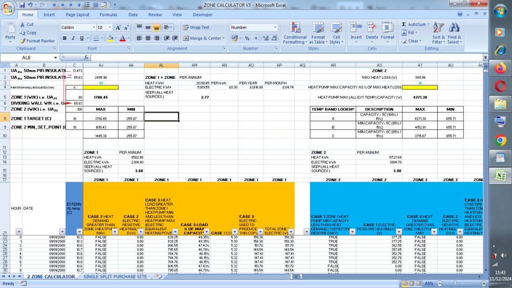
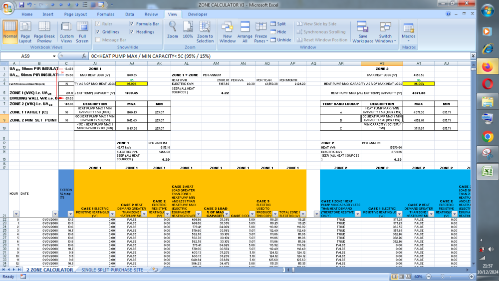
Not at all sure about that. For example, all I need do is choose the same Zone 1 / Zone 2 heat pumps (max power at 1700W / 4371 W) and change fabric loss Zone1 W/K from 29 to e.g. 60 and Zone 2 from 149 to e.g. 100 in the hourly quadratic (empirical based) calculator and the combined heat pump /electric heat source SEER drops from 4.22 to 3.77 (image attached). Personally I wouldn't touch any ASHP without a year or 3 of hourly weather data and also having carried out a fabric/airchange Heat Loss Coefficient calculation (W/K) after the refurbishment / extension was built to monitor the actual steady state heat loss over a week or two having heated it to a constant temperature. There are so many horror stories of installer calculated fabric losses / heatpump sizing resulting in SEER of 2 or less to be tempted by another way. The frosting / home automation supplementary heating / cycle limiting aspect also needs to be more fully investigated & implemeted too imho.
-
Does seem like a fly in the ointment in these parts. Bumped into a Monsieur Steamy thread a bit earlier today that had some good ideas but went cold: https://forum.buildhub.org.uk/topic/5928-ashp-frosting-cure/ So went looking and found an interesting "Frost free" Analysis - including a "non stick" cure but none of those seem available yet. Another one serves up taking images of when frosting starts so could maybe build some of that into a Home Automation routine. Not at all sure about that. Having stumbled across a Canadian empirical study that modelled a quadratic COP formula (steady state) to take thermal load (as % of max) and external ambient temperature into account (not yet sure how to reference it yet though but will look into that). I have a few years of hourly weather data available (Visual Crossing gives 900 odd free hours/day). So, randomly picking Calendar year 2008, after calculating the estimated hourly fabric / air change loss), matched that with the hourly A2A COP formula and enabled supplementary resistive heating to manage those hours when the heat pump maximum output was exceeded and turned the heatpump off when the minimum steady state output was exceeded to prevent cycling. Spreadsheet modelling changes to mini split max output power is straightforward and permits calculation to maximise what, I hope, could be a fairly realistic SEER. The example screenshot is a bit busy but, based on the 8784 hourly records, shows a 4.22 SEER for a 2 zone (2 mini split A2A) structure both set at 18C in the model example (will try to make that clearer in a follow-up later). There are no smart tarrifs available here yet but could already be natural gas price competive at that all source SEER (resistive / heatpump) heating even without considering off-peak battery sorage. Of course, Home Automation should be possible to acount for smart tarrifs.
-
U value calculation help required - Data sheet provided
NIMAN replied to ruggers's topic in Boffin's Corner
The instruction will be that the doors are normally closed (just me & her). Their very small R valus will be accounted for in this calculation. The bungalow will have a rectangular flat roof extension appended across the back -this will, usually, be the only area occupied througout the entire day. A single bedroom (of three) which will, normally, be the only one used is in the existing 1958 build area. I've fitted the 1958 suspended wooden floors with 75mm pir and calculated a (combined) U value for each room at around 0.25 W/K⋅m2 (accounting for respective P/A's) . The uninsulated attic will be insulated to full (or beyond) BC levels. The 1958 cavity walls (50mm) are "full-fill" with crumbling urea formaldehyde insulation. While my understanding is that The R-value of a cavity can range from 0.18 m2K/W for unventilated to 0.04 m2K/W for a well-ventilated one (as originally built), I simply stabbed at a figure of 018 K⋅m2/W for the now messily insulated/air gap mix 50mm cavity to arrive at a brick/cavity/concrete block/inside sand/cement render-gypsum finish U value = 1.75 W/K⋅m2 On a pension I don't think I can afford to do nothing but the more I read about my initial internal wall insulation plan the less I like the possible negative effect to building fabric of that so don't plan to improve their U values at all now. In summary, I currently imagine internal 50mm PIR internal wall insulation between the extension and 1958 existing build could provide some interesting savings if I set suitably low set-points on the cooler side to the 21C extension. The Excel calculator will tell the story. Absolutely. It was my last port since I couldn't find the required information anywhere else on line. Using rsi 0.14 x 2 (which I hadn't understood) will make some savings if I ultimately decide not to insulate the zone dividing internal walls. -
U value calculation help required - Data sheet provided
NIMAN replied to ruggers's topic in Boffin's Corner
For anyone following along and wondering the same thing - an AI query, initially suggested using an rsi of 0.14 K⋅m2/W for only one side of the wall but, afer I queried that, apologised (😮) and said that value should be used for both. In a relatively long conversation it supplied a lot of, obviously, technically accurate information and only made one other obvious mistake. I will use 0.14 K⋅m2/W for both sides in future calculations. Without a deeper dive it, sort of, makes sense. -
U value calculation help required - Data sheet provided
NIMAN replied to ruggers's topic in Boffin's Corner
I'd like to size a number of A2A minisplit heatpumps as zoned heat emitters in this 1958 Bugalow (targets being a mixture of 21C / 18C & 16C). Internal walls have both sides finished with 15mm sand/cement plaster render & gypsum finish to 100mm dense concrete block Estimated as: thickness (mm) λ (W/K.m) R 15mm sand/cement plaster & gypsum 15 0.5 0.030 100mm dense concrete block 100 1.4 0.071 15mm sand/cement plaster & gypsum 15 0.5 0.030 Sum 0.131 K⋅m2/W U 7.609 W/K⋅m2 For the external envelope total heat loss wall calculation I used rsi (intenal surface) = 0.14 K⋅m2/W & rso (external surface) = 0.04 without really investigating the underlying Physics involved. For the internal walls the inclusion of rsi/rso would, obviously, substantially decrease the conductance calculated above. If I should include them are there published values of what they should be and (if they are different) to which side of the wall (warm/cold) should the respective values be applied (not that I see this last point making any difference for emmitter sizing). Depending on the modelling I will consider applying internal wall insulation to various regions of the internal walls. -
Repurpose gas combi for hot tub (analysis/shortlist stage)?
NIMAN replied to NIMAN's topic in Boilers & Hot Water Tanks
Reading my comment again I know what you mean - neither do I entirely !! The differential equations associated with transient / dynamic simulation of a water to water heat exchanger look like they will take a while to understand. I also imagine, in my case, that they will need an iterative (discrete) Euler approximation to solve so spreadsheeting / programming that may take a while and be computationally intense (this is an old Win 7 laptop) In the meantime, therefore, please let me get back to basics to see if I do have some simple, but real, understanding of how modulation works or is likely to. To make things as, conceptually, simple as possible I hope the following are reasonable assumptions: a/ let the combi CH flow/return be directly connected to the hot tub (i.e. no new water to water heat exchanger involvement) b/ assume hot tub is infinitely insulated (i.e. Zero loss) c/ assume the hot tub is always perfectly mixed (zero temperature gradient throughout) d/ assume combi internal combustion chamber pipe and hot tub connecting pipe volume is negligible e/ 1m3 mains tap water is used to entirely fill hot tub at 5C In an attempt to identify the maximum combustion chamber to water instantaneous available power - the combi installation manual states: "CH heat output range 40C flow / 30C return 9.8 to 26.0 kW" Therefore, assumption is that maximum flame /fan can generate 26 kW The integrated pump is single speed (apparently of the non-modulating variety)- the installation manual states: "Circulation water volume (delta T =20K)" = 1032 l/hour Analysis based on above (simple as possible line by line): 4200 J/kg°C SPECIFIC HEAT WATER (assume at all temperatures) 1 lite water = 1kg (assume at all temperatures) 1032 l/h = 0.287 litre/sec Circulation water volume 60 C manually adjust boiler set-point flow temp to this The available 26kW (assuming max flame/fan) provides an uplift to a first 0.287 litres of CH flow of: 26000/(4200 x 0.287) = 21.570 K This first 0.287 litres enters the hot tub at (21.570 + 5) = 26.570C and is instantly mixed to raise its temperature from 5C by: 26000/(4200 x 1000) = 0.00619 K At the start of the 2nd second the CH return is therefore 5.00619C The boiler flame / fan is maintained at max (modulation logic only reduces these if flow equal or greater to 60C), A further 26kJ is added, to this subsequent 0.287 litre, over the following second and enters the hot tub at: 21.570 + 5.00619 = 26.576 C (measured at CH flow thermistor, so flame/fan kept at max) The additional 26kJ is instantly mixed and the hot tub temperature becomes 5.00619 + 0.00619 = 5.01238C This is the CH return temp at start of third second i.e. CH flow temp rises, linearly, by 0.00619K every second until Hot Tub thermostat call for heat ends at 40C. In this entire heating period the flame/fan are kept at max as the CH flow thermistor never rises to 60C. The hot tub requires a 35K uplift to attain it's thermostat 40C cut off. This will take 35/0.00619 = 5654.28 sec (1.57 hours) Is that all pretty much correct (or fantasy)? If, instead, the boiler set-point flow temp had been initially set to 30C (hot tub thermostat still calling for heat until 40C) then what does the combi modulating logic do: e.g. full flame/fan until CH Flow thermistor sees 30C then works it's flame down quickly to lowest output power but then sees a subsequent CH Flow thermistor reading above 30C and then shuts the flame/fan off but keeps the pump going in expectation of a future CH Flow thermistor reading below 30C in which case it would immediately fire again at max fan/flame or have some memory logic to try the lowest fan/flame first (or something)? Another thought (with CH Flow at set point 60C) - If the gas flame is around 1960C, am I correct to imagine the transfer rate drop slightly from 26kW as the CH return linearly increases from 5 to 40C? -
Repurpose gas combi for hot tub (analysis/shortlist stage)?
NIMAN replied to NIMAN's topic in Boilers & Hot Water Tanks
Looking at this again, just to be sure I have it straight / not: The gas-combi instruction manual includes, for example "CH heat output range 9.0 - 24.0 kW" For info, on the off-chance it matters - simple thermostat on/off control was used in the combi boiler while it was hiustorically used for space heating (no bus modulation device was ever employed). For case B, is it/could it be correct to imagine that either of the following apply: a/ as the combi return thermistor registers a gradually increasing temperature it then modulates (in combination with the flow thermistor reading) the flame in order to keep the flow temp to set/target value (i.e. load matching)? b/ the above at a/ is not the case - rather, some Vaillant predefined return temp causes the flame to extinguish entirely and the pump to continue until some "other" condition is met at which point reignition occurs (i.e. on/off at max power output)? I'm tentatively assuming that the boilers internal single stage pump supplies a constant flow. Example repercussions: If a/ is true and the boiler (at target 60C) automatically modulates down to meet the Electro-G2 (as per link) load then, for example the hot tub open top/occupied reheat time (from 38 to 40C) will take, rather than nearly 5.75 mins at, say, 24 kW to replace the 2.3kWh will take, say, 2.3kWh/13kW = 10.61 mins? If b/ is true on heating the entire 1000 litres from cold once its temp reaches 30C (delta T 30) the Electro-G2 max dissipation to hot tub falls to 20kW and the boiler will continuously cycle on/off all the way to tub thermostat stopping call for heat at 40C (since the boiler is still trying to produce mismatched 24kW)? -
Repurpose gas combi for hot tub (analysis/shortlist stage)?
NIMAN replied to NIMAN's topic in Boilers & Hot Water Tanks
Not sure whether that or skin soup is worse ☹️ Yes - that is definitely the sort of thing that (I imagine) I need to contemplate - thanks for the link. Could it not be more reasonable to think that the instruction manual delta T 35K RISE AT 11.5 l/min is the max transfer rate (instuction manual Mad DHW output 28kW) from the gas to water exchanger into the water to water exchanger? i.e. to achieve this the gas flame is set at max, all available 28kW is sucked out of the water to water heat exchanger leaving nearly 5C as return water temp to gas to water exchanger but that then supplying output at, or near, max 85C flow to the water to water input (that's all imagination since I haven't considered the combi pump flow at all yet). On that basis seconds to heat the metre cubed is 147 / (28/1000) = 5250 (1hr 27.5 min). If there is any truth in this it would probably mean that most gas combi's in UK are in condensing mode during DHW most/all of the year? Hmm, having said that the combi doesn't know the mains water temp. If the DHW setpoint is 40C then is it more likely that the the flame is always modulated to, er, "some" level ? -
Repurpose gas combi for hot tub (analysis/shortlist stage)?
NIMAN replied to NIMAN's topic in Boilers & Hot Water Tanks
Oops again, error corrected inline above ☹️ -
Repurpose gas combi for hot tub (analysis/shortlist stage)?
NIMAN replied to NIMAN's topic in Boilers & Hot Water Tanks
I previously said this: As you say, the humongous mountain is, in reality, a molehill (my fault for first mention of - please forget it). An automated script to add 1000 records (6 week days) to a database takes milliseconds to run and zero amount of my time. Surely, hourly heat loss calculations and boiler / heat pump sizing based on median / mean hourly over 30 years is more sensible than those for an, idiosyncratic?, 1 year period. Appreciate that and enjoyed the Rumsfeld like comment. For the (very) unfamiliar with all the subject matter (me) it seems possible the failure(s) could occur (equally?) on the gas to water flow temp side - could the risk not be managed by precautions (or a preponderence of those) on the hot tub side? Appreciate this again. That's what my original post referred to "impossible". For the unfamiliar can you, again, please explain Why? OK - i'll consider that more before further comment. My comment is directed at initial filling without occupancy but understand your concern - thanks. I've briefly considered A2W and, for use case, do not, currently imagine it is suitable. I wish to consider very fast heat up times (or as quick as possible from weekly empty throughout the year for convenience) and don't, currently, plan to have a large diameter electric cable feeding a big enough A2W heatpump in the vicinity to do (electrically / Capital outlay) that job (the COP of that unit will be relatively awful cf gas in bleak mid winter into the bargain). For 40C maintenance, with cover off, I'd plan to run the gas combi flat out (probably making set flow = 85Cs) over a short period to raise from 38 to 40C as described in a previous comment - the aims of my analysis are to avoid short cycling and always be condensing so not at all sure what you mean here. The combi would have to run flat (no cycling) for nearly 10mins at, say, 24 kWh to replace the 2.3kWh lost by 2C cooling - I can't imagine demise by that any time soon - can you? No problem at all here Nick. I'm just searching for facts based in Physics/Chemistry & Engineering (not so much rules of thumb or that should do nicely). I've done all of 3 those a bit but am trying to get better before I can't ☺️ -
Repurpose gas combi for hot tub (analysis/shortlist stage)?
NIMAN replied to NIMAN's topic in Boilers & Hot Water Tanks
Congratulations. Most people are a waste of spacetime.

