mattgibbs
-
Posts
31 -
Joined
-
Last visited
Recent Profile Visitors
2421 profile views


mattgibbs's Achievements
Member (3/5)
4
Reputation
-
Any pictures on how it turned out? I want to use the QIC trims for the shadow gap skirting but not sure how to finish it off when I get to internal doors that are ultra flush with no architraves , thanks
-
 Ah okay 👍 so if I had an RGBW compact dimmer tree in a loft space with a small 24v power supply then that ground would still need to be commoner back with those in the cabinet
 -
It’s just the unfortunate shape of the house which is 8m wide but very long that makes for these long runs. I didn’t really plan for a cabinet anywhere else
-
Im not expert but my build features the loxone mini server which has tree turbo and will connect with 10 speakers so no audio server or extensions! Im sure the tree turbo on the audio server also means you can add more speakers without extensions
-
That was based on daisy chaining all 10 speakers but if I run power separately to each speaker from the cabinet as you suggested then it's a none issue
-
@Thorfun That's one way, any ideas on the speaker cable question?
-
That's the cable im looking at, it is capable of powering 1 speaker at 30m distance but as soon as you add 2 or 3 or in my case 7 speakers in one room the cable is no longer big enough unless powering each speaker individually. also I still don't know why this audio cable on their website is showing the 2 x 1.5mm cables as 230v rated when the speakers are 24v
-
I think my mistake was calculating the full 8A of the dimmer over that distance hence the silly cable sizing. But your right, on a per channel basis at 2A even my longest run at 25m requires a 2.5mm cable which isn't too bad I suppose. That's question 2 answered.
-
Im Currently planning my Loxone build and would appreciate if anyone can help answer a few questions mostly related to my struggle to get 24v to work for anything part from low demand items like switches and sensors due to long runs and huge cable sizing. 1. I will be using the mini server compact's tree turbo to connect with Master and client speakers and in one room there are 6 speakers + 1 sub and at 20w a speaker and a 40m overall run from the cabinet requires 13mm2 24v cable which seems insane. Should each speaker perhaps have its own 24v driver in the ceiling using Loxones new audio cable capable of 230v? I can't think of any other reason loxone have made a 230v audio cable for 24v speakers... 2. When maxing out the 200w of the rgbw dimmer tree at distances of 15/20m from the cabinet to led strips, cable sizing of 10mm2 is required. is it better to just hide a rgbw compact dimmer local to the lighting with a local power supply that way 24v cable is only required for a short distance? if local power supply is the best option for the above two questions then im going to have a lot of power supplies all around the house which brings me on to a third question.... 3. I see your suppose to common the grounds of the power supplies which is easy in the cabinet, but do power supplies that are local to lets say a speaker or a RGBW dimmer tree compact in a ceiling also need to be common with the ones in the cabinet? Forgive me if I have missed something obvious!
-
Can anyone let me know if the Loxone power supply and backup fits in the standard depth future automations enclosure or does it require the deeper enclosure?
-
@SimonD what would be an example of room influence controls and how does it differ from zoning? Will the MVHR not just negate any differences in room temperature anyway. For context I'm purely looking at downstairs UFH at low temps, air tight house with mostly large open plan areas. Bedroom heating, im hoping will come from heat rising from below combined with the MVHR distributing air evenly and being topped up from electric radiators in the adjoining en-suite's
-
So my setup will be ASHP and UFH downstairs. In my situation i dont see how having zones and thermostats would help. If there were some solar gain then this would have a quick effect on heating up a room. If there were a thermostat in that room which then stopped heating that zone what would that actually do? the slab would presumably remain a similar tempreture for hours and have no short term effect on the room tempreture. So long as the system is balanced and rooms are heated evenly, is any more control other than weather compensation in the heat pump really needed?
-
@Conor thats lucky, ive not found a way to merge the upstairs zone with the downstiars one. I know right! ive been getting lost in the world of the fan coil units vs air con debate today but i think i will just go with cooling the downstairs slab and air con for cooling
-
@Conor Glass is already all in to be fair. its also mostly south facing but fortunatly our overhangs keep to sun off the glass in the summer almost entirly. But no we didnt do a heat gain/loss model did you have any idea on my comment above about Loopcad only accounting for the downstairs heating requirements?
-
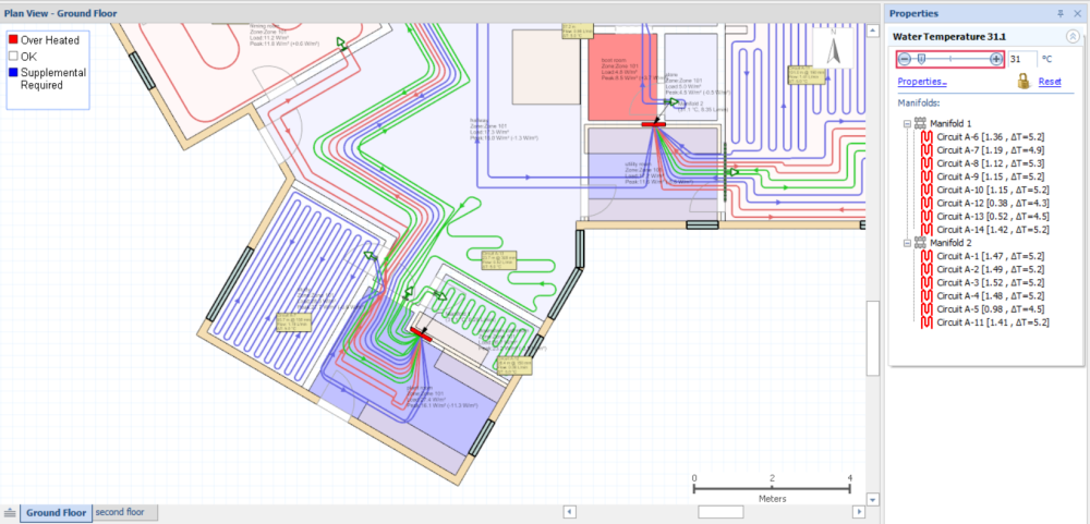
Also does anybody know how i can make LoopCAD count the supply and return pipes towards the room heat. Our plant rooms and hallways show as needing supplemental heating when in reality they are probably going to be hotbox's? Ignore the pipe layout in the triangular room as i still need to space it out. but there is a large amount of pipework in the plant room (lowest room pictured) which is showing as being to cold and same for the hallway but there is no way thats actually the reality.