ricardo100671
-
Posts
33 -
Joined
-
Last visited
ricardo100671's Achievements
Member (3/5)
0
Reputation
-
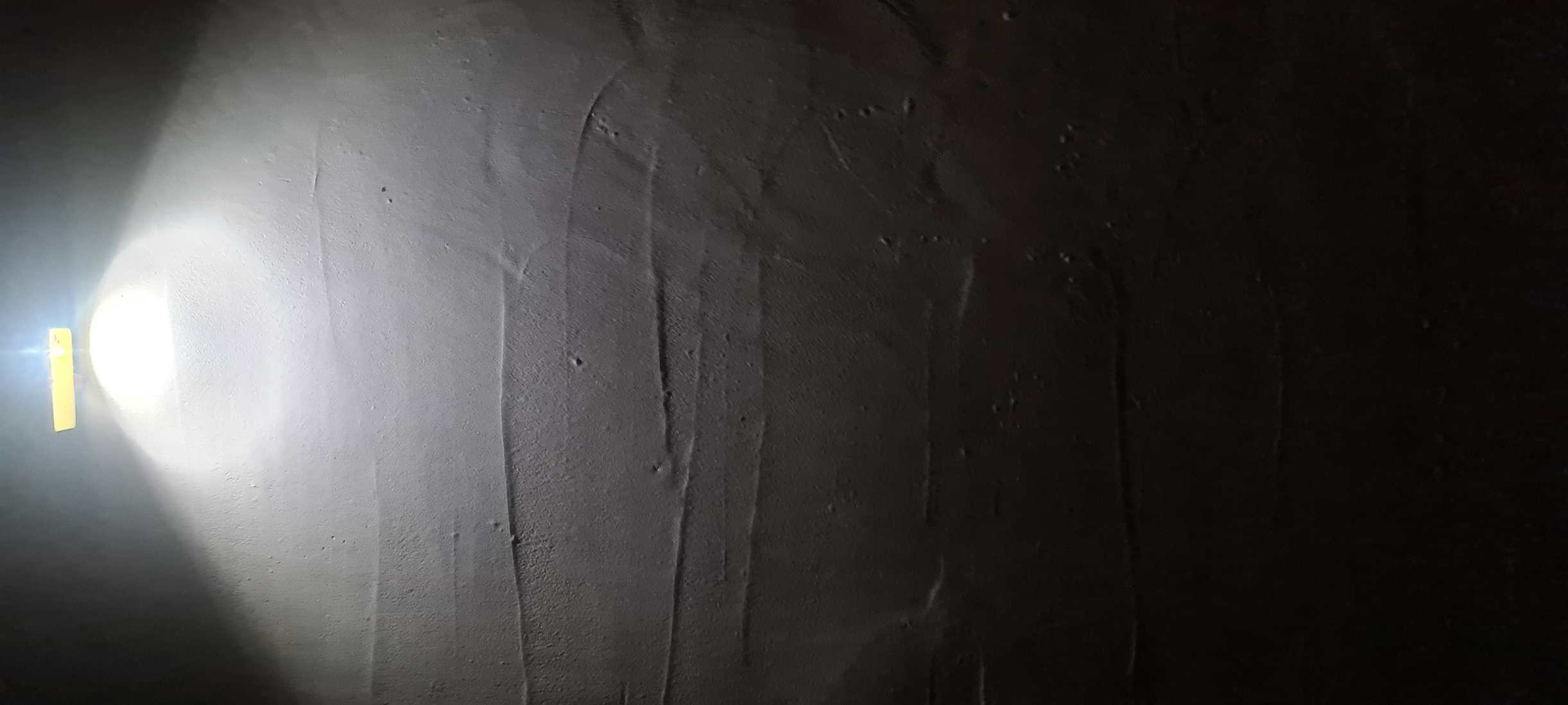
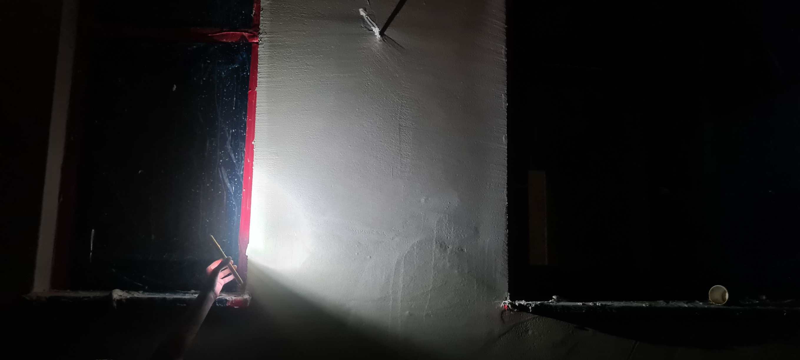
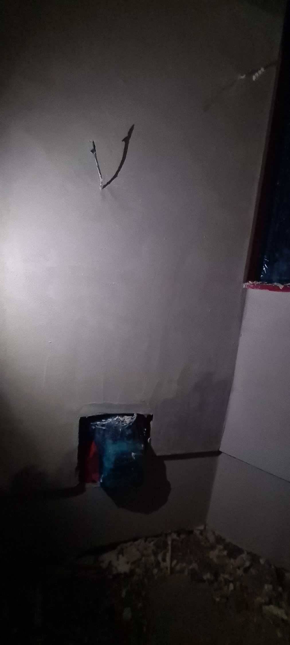
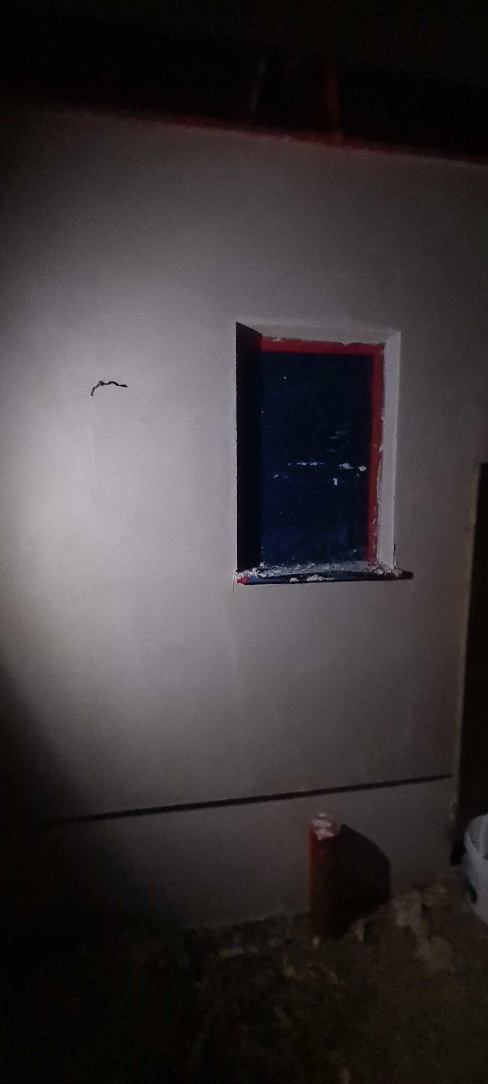
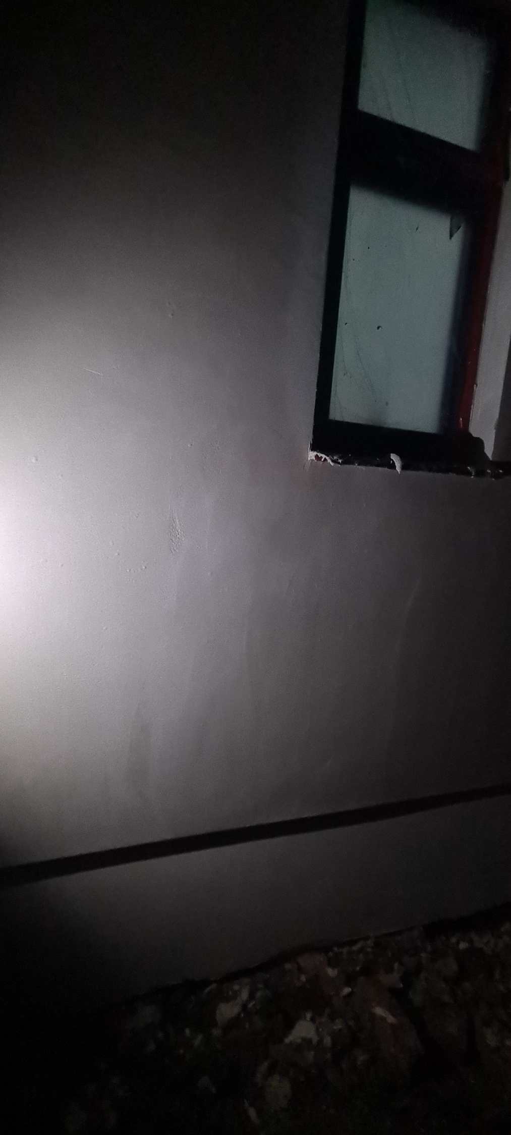
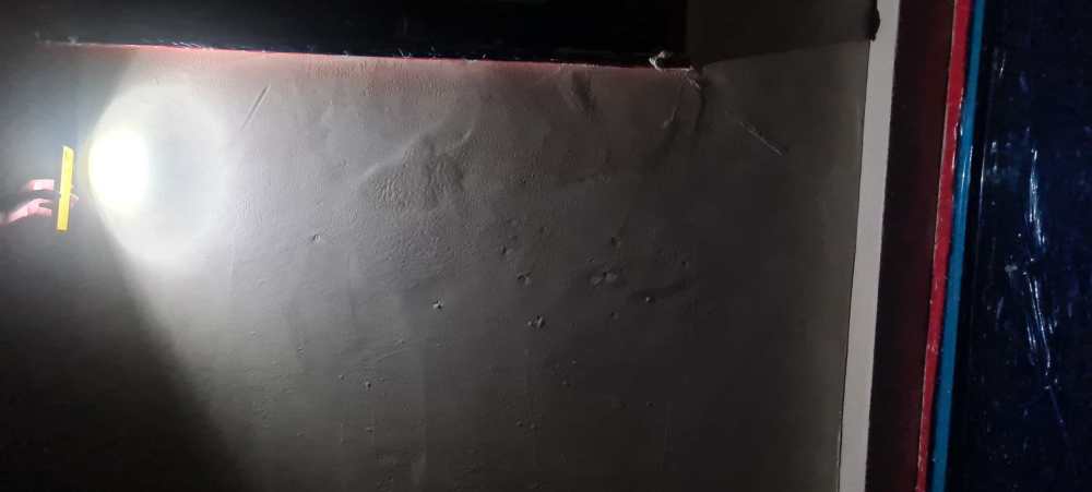
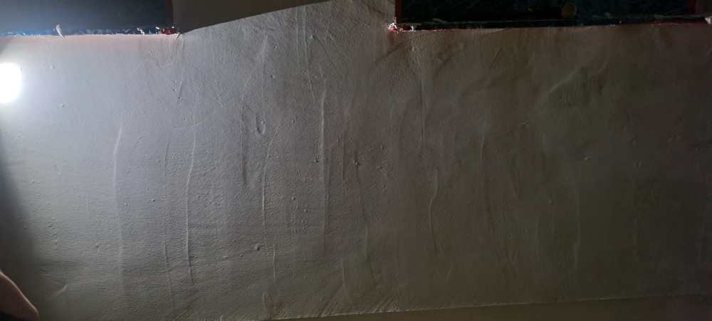
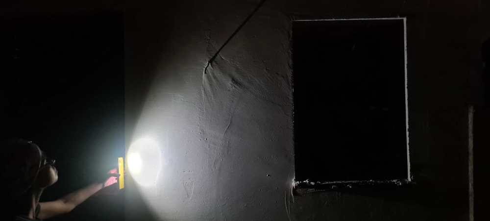
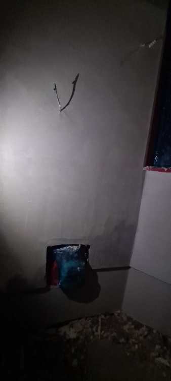
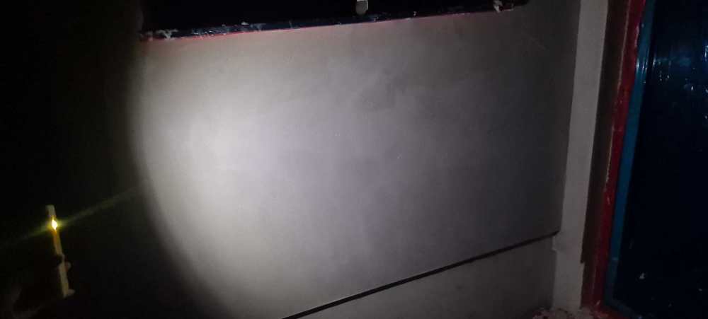
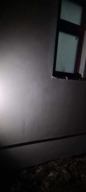
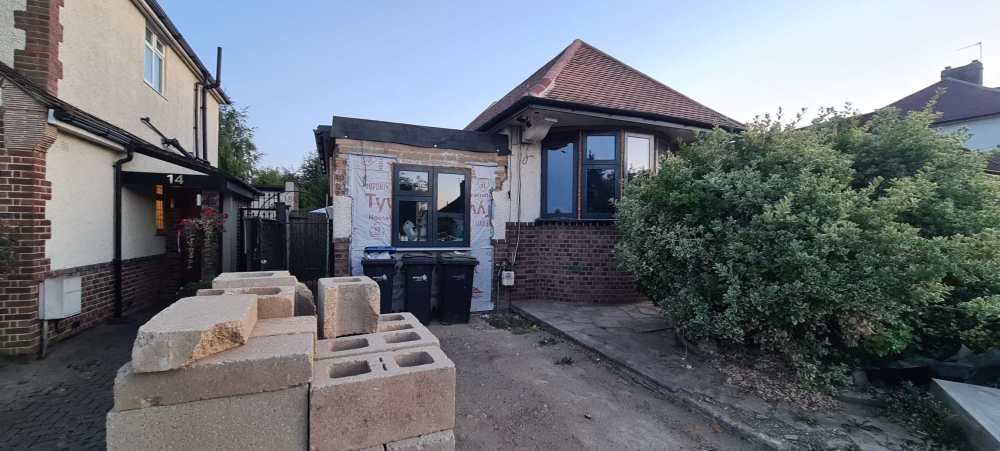
We are have our EWI finished with 1.5mm silicone render and plan to iluminate the walls with up/down lights, so need a good surface finish. Looking at the my plasterer's mesh and skim coat under makes me very worry that the finish will not be flat good. I understand that there is still the top coat to go on, but given it is only a 1.5mm by understanding is that it will reflect the skim finish and therefore should be representative of the final result. But I do't want to be over reacting, in the event that this is an acceptable skim coat finish that will still give a give finish. Please see photos


-
In response to your points - Vaillant wiring centre to wire in the mixer .... Yes I have now bought the VR71, which I think may be overkill, I think VR70 would have been enough, and have a sensoComfort and weather compensate connected already - You need a pump on the UFH ... Based on UP other vids about caldulating heads etc. I figured my system is low enough to be handled adequately by the boiler pump, since it is all ground floor and all rads are fed from manifold all with smooth curves. As for the flow rates, Can't understand why this can't be managed by flow restrictors on the manifold. I could check the deltas on the return to ensure I get correct flow for every loop, incl. rads. Any reason this would not work ? - You need temperature sensors on your pipework so that ... I see, yes I will have this as part of the VR71, but, I wonder, is this why I need the hydraulic separation .. I did note his mention on this, but did not elaborate and I guess I did not quite understand. If it is about sensing different temps for each circuit, would a sensor on flow before each manifold input not achieve this ?
-
Yes Correct
-
I did that based on the Urban Plumber's vid you posted above. You can see right at the start his manifold setup seems to tee off both flow and returns. If I need two circuits would I need 1 or more valves on this pipework somewhere ?
-
We have a 193 Bungalow, plannig to attach 2 layers of 50mm K5. Problem is Upper half of walls, is pebble dash, protruding by ~25mm and therefore would like inlfill lower half, as cheaply as possibe. Thinking to use 25mm XPS all the way to the ground, then over the lot with the K5. So, effectively, would have three layers on lower half (XPS+K5+K5) and two upper half (K5+K5). Would glue first layers with EWI 225 Premium, possibly full face coverage for the XPS and D&D for the K5. Then mechanically fix next layers with centered single fixing per board, followed by top layer with 5 fixings per board. Folks at EWI store told me I could not do 3 layers i.e. XPS+K5+K5, something about the K5 faces being to smooth, or something, allowing movement between layers, and advised to build up lower half with their mortar infiil, which would require 153 bags costing 1600 ex VAT and labour ! If movement between layer is really an issues, could I not just also add thin layer of adhesive between layer? Thanks in advance for any aevice
-
That is great ! Thank you. Just a couple questions after watching that - At around 1:00 he seems to describes how the valve maintains temperature by pushing the flow out to the return, but the at 1:40 he seems to state just the oposite that cool water is coming in to the valve from the return, which is how I thought mixers valves actually work ? - Do I need to have two circuits, if I only have a single zone, my thinking was that the ESBE will just always keep the UFH set at a relative temp to the RADS. So system flow would be 50 and I would restricit the ESBE set point so the UFH flow is only 26. Then the system should remain balanced if. i.e. if boiler lowers or raises flow temp depending on weather compensate rads/UHF flows should remain constant at same ratio. (hope that makes sence) - Why would I want to turn the system off if outside temperature reaches certain temperature ? I that not the job of the Stat, based on inside temperature ? This is how my system was plumbed. Aside from the controll centre and pipe sensors, I dare ask how wrong it is and what else I am missing on it to get it working ? Thanks again for all the advise

-
Thanks @JohnMo. Yes I have mixed system. My rads need to run at 50degC and UFH at 28. Did not get the wiring centre yet as not sure which one to get, of if I even need one, given my simple system. If I do get one, I assume would treat the mix valve like any other actuator, but what is confusing to me is that, my understanding is that the actuator is controlled bassed on the related connected stat, so that the actuator is closed when the stat reached setpoint, but for the mixer valve there is no stat. Does that mean I should have fitted a floor sensor stat and that is what is paired with the valve at the wiring center ?
-
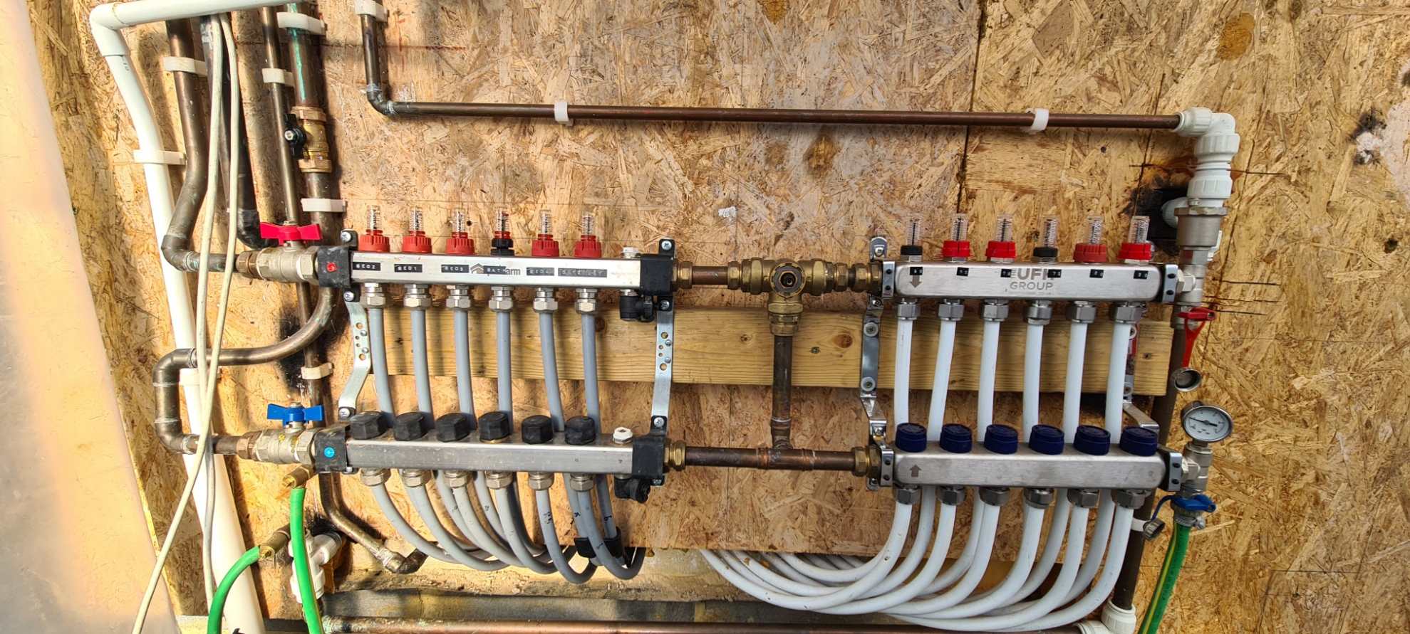
I have followed this advice, from Urban Plumbers, and fitted an ESBE motorised valve to my manifold as mixing valve for UFH, but not sure what I need in order to connect it to my Vaillant ecoTech Plus. It is a single zone setup with 1 sensoHome Stat and weather compensate. Thanks in advance for any help.
-
My bathroom has two lighting loops, House and Mood. We have an illuminated mirror, which I would like turned on with either loop. Can this be achieved please ?
-
Thanks for the very detailed advice
-
Floors undulate cross joists about 7mm and dip down by one wall to 10mm over about 800. Planning 12mm laminate over, which brings up another question of whether I still have to use underlay if I do pour leveling. Also its about 74sqrm into four connected rooms
-
We are considering leveling out our joisted timber floors with Setcreet Latex Self Leveling compound to 7mm avg. thickness. The deck is ProWarm UFH routed boards with 6mm over ply. Some people have said tis is a waste of money as it will eventually crack and crumble over time due to vertical flexion form walking. We can see a bit of movement when we walk but wondered if concrete would weight this down and give a more sturdy base. Has anyone has success/Issues with this ? Thank you
-
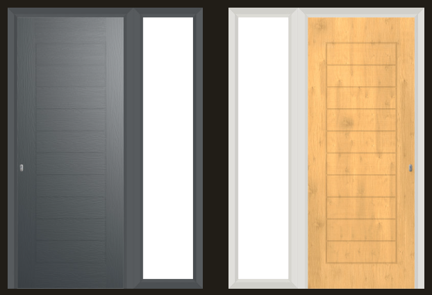
I am designing a door with Solidoor designer and one of the option is to ommit the coupler, which is me preference. The overall door dimensions are 843 Door +357 sidelight. I assume, without the coupler the two are screwed together for each side, with mastic between ? Would this pass Building Control ?
-
There is no doubt that there is a leak, question is about solutions. Thanks