


blankton
-
Posts
24 -
Joined
-
Last visited
blankton's Achievements
Member (3/5)
1
Reputation
-
Thanks. Do you have a link to the staples? I am trying to work out the gauge. If I can get a stapling system that works, it will save a lot of time. But otherwise I'll have to try screws and washers or clout nails.
-
This might seem a stupid question, but has anyone got any practical knowledge of stapling these up? I've got them fitted, but before I add insulatuon and seal the gap with plasterboard I want to get plenty of staples in, as currently there are only a few and there are some detectable air gaps. I've read the importance of many staples. The issue I have is that I'm really struggling to get staples in. The floor upstairs is a standard 22mm chipboard flooring, as used on new floors these days, it just seems too hard for the staples. I've tried two standard staple guns. One an old school manual gun and a tacwise electric stapler. These are both firing a medium thickness (18ga) staple. However, they just crumple up. The staples are 10.5mm across the crown, with an 8mm leg length. Thicker gauge staples are made in 15 or 16ga, but they seem to have either very long legs (25mm) or have an unusual shape, such as a curved crown. I would need to get a pnulatic stapler as well. I'm not against getting a pneumatic stapler, but I can't see any that fire a standard looking staple, but in heavy gauge wire (which is what I think I need). I've spent hours looking at staples. Aside from staples, the best solution I've found so far are 13mm clout nails (like you'd use on your shed roof), but this is very time consuming. Does anyone have any advice?
-
Have you ever used it? How would you circulate the water? A standalone pump, or rely on the ashp to still be pumping?
-
Thanks. I've found the manual online. Seems similar to the Grant one, except the Grant one has had some sections removed! I'll have to have a better read when back at my pc.
-
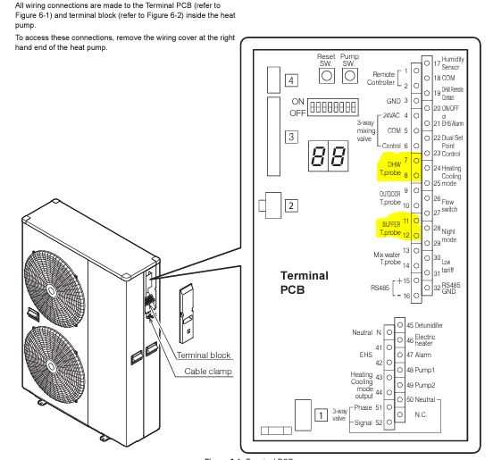
Hi All. Following a slightly embarrassing issue with a non-return valve, I've got my ASHP up and running. To commission it I've just set it up like a standard S plan heating system on a boiler, with the room stat and DHW stats being effectively on/off switches, controlling the call for heat at the heating and DHW terminals on the heat pump. However, I am aware that I have the potential for some extra goodies on this system. DHW immersion. I think the primary "excuse" for this is legionella, but I'm thinking it might be more useful as a back up in case of breakdown. The heat pump PCB has 2 terminals for "backup DHW immersion", but the installation manual gives no further info on these terminals. I assume I would need to use a relay and not pull 3kw through the PCB. but there is no info on control of the immersion (its a Grant Aerona 6KW BTW). I'm thinking I might take the DHW immersion out of the ASHP equation and just fit a normal timer with "boost" button. This seems a better idea as a backup, as it can be used even if the ASHP PCB is nuked. Buffer tank immersion. I brought a new second hand grant buffer tank (50L) from ebay and it came with an immersion. I'm thinking of at least running wiring for this. Has anyone ever used one as backup to run the UFH? I'm not sure it could keep up, but it would probably be able to run one floor. If anyone has done this, how? If the ASHP was totally kaput (including pump), I'd need to also include an inline pump. I was also wondering if this immersion might be useful to give a "boost" to the heating in very cold weather. Obviously it might not be very economical, but for the handful of very cold days maybe it would be useful. The installation manual seems to allude to this by saying the following "A ‘Volumiser’ tank is simply a vessel used to increase the volume of the system, to meet the system requirements as given below. It will have only two connections, one inlet and one outlet, and it must be fitted in the flow from the heat pump if the volumiser contains an immersion element that is to be used as a supplementary heater. " but other than this paragraph, there is no further information of how to go about this. I could wire it up separately (as I am planning on doing for the DHW immersion), but it would seem better to me if the ASHP knew it was there, so it could call it up if it was going to ice up or otherwise struggling. Any thoughts on this? Final thing is that the ASHP PCB has terminals for DHW and buffer temp probes. At present the DHW stat is just a binary on/off switch, connected to the programmer and general S plan heating controls. I am assuming these terminals on the PCB would take a thermocouple output and therefore allow the ASHP to see the actual temperatures at this point in the system. Have I understood this correctly (again there is not much info in the installation manual). Is there some advantage to the ASHP being able to see the actual cylinder temp, rather than just seeing a "call for heat", but not knowing how far it has to go? Thanks in advance if anyone has any thought on any of the above. I'm currently sealing up any insulation gaps before boarding, so if any more wires want running, now is the time for me to do it.
-
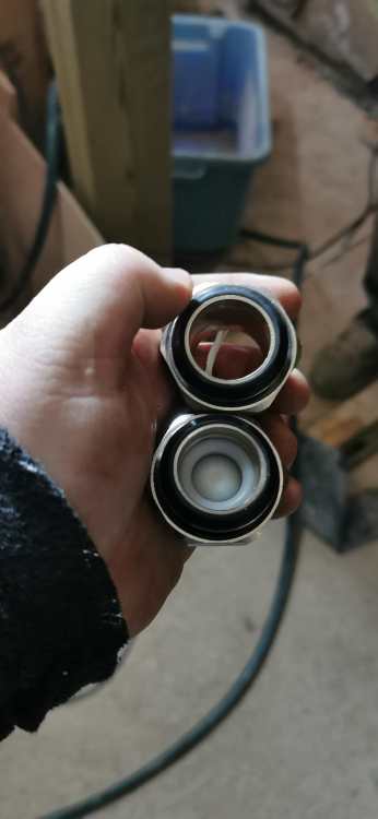
Thanks for the advice. I set about deleting the blending valve and pumps today and the issue became obvious........ I'd ordered 2 identical kits and built them up on a bench. There should be a non return valve between the blending valve and the hot manifold, on the bottom (cold) manifold this non-return valve should not be there, with just an open union to fill the space where the non return valve is located on the top manifold. I had used both non return valves on one manifold and both open unions on the other. The manifold with no non return valve (top floor) worked fine. Not surprisingly, the one with an entra non-return valve, which was pointing the wrong way, didn't work 🥴
-
double post due to image issues.
-
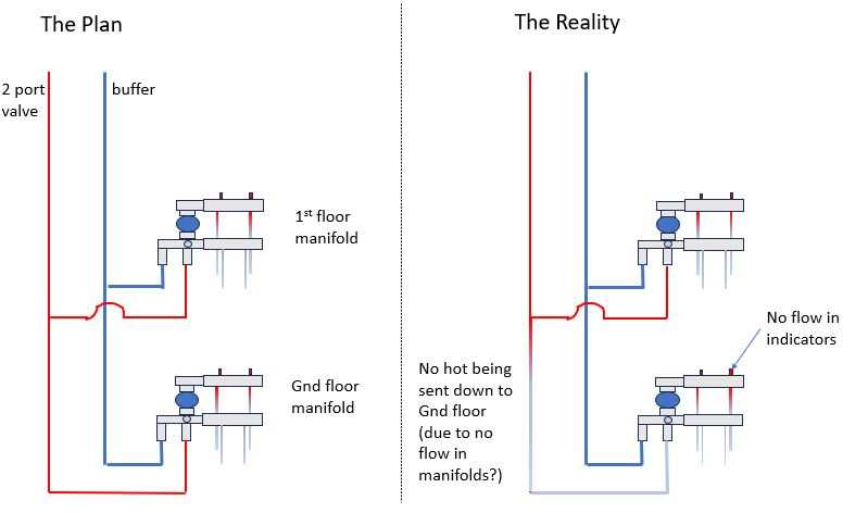
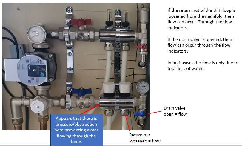
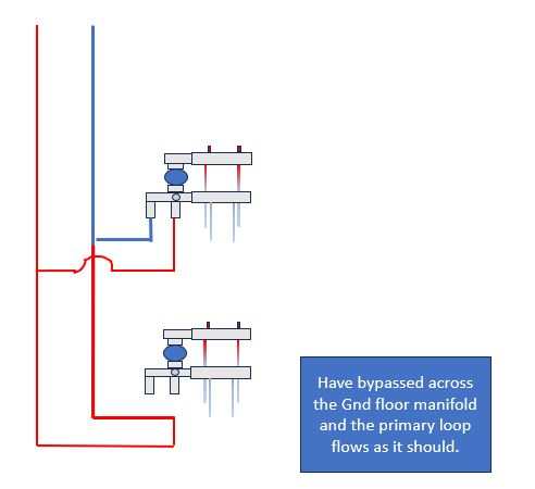
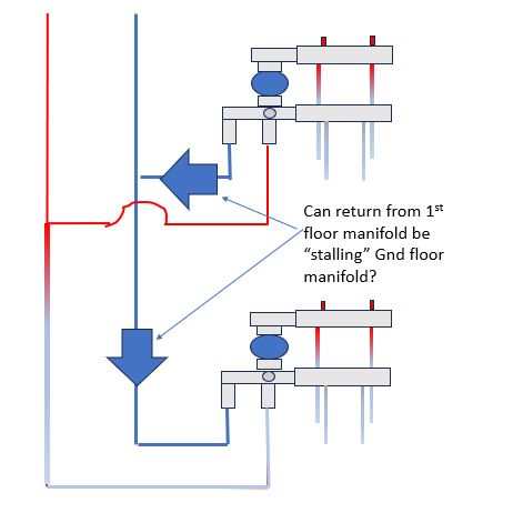
Hi. I am currently renovating an old cottage. I've fitted wet UFH upstairs and downstairs. I was advised to have one manifold upstairs and one downstairs to reduce the chances of air locks, so this is what I did. At present it is effectively one big heating zone. I had also read advice against having lots of zones, so I am going to try and just balance the heating of the single zones, by playing with the flows. I've fired up the system and while the top floor manifold and blending valve seems to work as it should. The bottom floor one isn't. There is no flow at all occurring downstairs, either in the primary circuit down to the manifold, or through the UFH loops. Here is a schematic: I've messed about with quite a few things: - if I pop off the UFH loop return from the manifold I can get flow through that loop (albeit with the water going all over the floor) - If I use the "cold" drain valve, I can also get flow (again with the water being lost from the system. When I do both of the above, warm water is drawn down the primary circuit towards the blending valve. - I've also bypassed the ground floor setup, this results in the flow round the primary circuit, so this external pipework seems ok. The manifolds are cheapish things from an online store. I fitted one in my current house 15 years ago and it has never skipped a beat, which is why I went with the same again.However, in my current house I only have 1 manifold and radiators in the rest of the house. My current thinking is either I have a rogue faulty manifold, or the way I've piped them up in series is causing some weird back-pressure effect. Should I perhaps of put a check valve between the 1st floor return and the ground floor return, to prevent the first floor return from applying a pressure to the "wrong" side of the mixing valve? I should also add that I've filled each loop one by one using a hose through the drain valves on the manifold and I've also tried switching the flow and return on the ASHP, in case the flow and return on my Chinese manifolds was the wrong way round. Sorry for the long post.... I've spent 3 days poking about at this, probably longer than it took to pipe it up in the first place! I'm hoping that I've done something fundamentally wrong with piping the manifolds in parallel and it will be instantly obvious to anyone in the know. Next thing I am going to try is getting rid of the pump and blending valve from the ground floor UFH and just put the flow and return straight into the respective manifolds. Since I brought the blending valve and pumps, I've since read that they are not really necessary with ASHP due to the lower flow temps. edited to sort photos.
-
I'll post up the schematic later. The filling loop comes off the cold after it's already gone through the 3 bar reducing valve (that they also stipulate), so I'm limited on what pressure I can achieve via overfilling. I appreciate that if the external isolating valves were shut off to the hp, I'd then be isolated from the prv within the hp. But I'd also be isolated from the source of heat 😂. We would then be down the road of sharpeners suggestion that the immersion boils the cylinder and transfers heat to the coil, but the length of time this would take, would need the cylinder start on the immersion to have failed. It all seems highly unlikely, but I guess I better fit it to comply with the manufacturers instructions. It's just another series of pipework joints and a component that will need maintainance. I plan to fit it next to the cylinder (on the return), it can have its own tundish, but share the 28mm drain pipe to outside that the cylinder prv would use. The convinient place that it is shown on the manufacturers schematic, (on inside wall next to hp), isn't so convinient in real life.
-
I am currently fitting a Grant 6Kw heat pump. According to the schematic, there should be a 3 bar PRV and tundish on the primary heating circuit. Obviously there is one on the unvented cylinder and the reducing valve. However, this is showing one on the primary circuit. The exploded diagram / schematic of the heat pump shows an internal PRV as well. Why two?
-
Hi Sorry, I have only just seen this. Still not finished. I am just getting to the stage of piping up my ASHP. Even without the heat on the foamed glass / limecrete does seem to have completely dried out the ground floor.
-
Spreader plate floor covering - 10mm ply?
blankton replied to blankton's topic in Underfloor Heating
about 48 screws on a 8 x 4 sheet. -
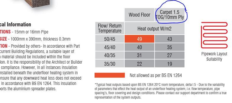
I have just installed some spreader plates for a wet UFH system. Due to the existing floor being uneven and noisy, I have build a framework of 3x2 CLS at 400mm centres. The attached datasheet gives heat output with two floor coverings - wooden floor or 10mm ply and carpet. Have I misunderstood this - the manufacturer is recommending 10mm ply as the deck on top of the spreader plates. I can understand that its best to keep it as thin as possible, but 10mm seems very thin. We have tried a sheet and put a lot of screws into it, but if you are between the centres, it does depress slightly. The small amount of deflection would probably not be noticeable, but I am concerned that this repeated movement might eventually cause the pipes to wear or fatigue. After the mammoth undertaking of fitting this system, I'd like it to last very long time and not be pulling up boards due to leaks in a few years time. So - am I worrying over nothing? Have I misunderstood the manufacturers spec? Has anyone used 10mm ply in this application before. If not, what should I use. I guess if I stick with ply I can keep it thinner than chipboard (22mm) as its stronger. 15mm, 18mm? Many thanks for any advice.
-
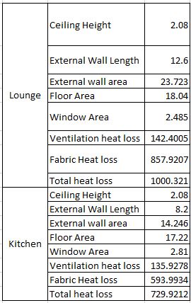
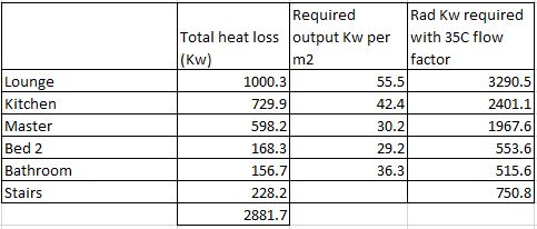
Whatever I was doing, I'd have laid the ground floor underfloor heating, as I needed a new floor, so its literally a couple of hundred quid extra to put some pipe in the floor. I have GF UFH in my solid walled Victorian kitchen and its great, so there is no way I wouldn't have incorporated this on the ground floor, regardless of the boiler type. However, I am kind of wed to the ASHP solution for other reasons - I've been given a Grant 6Kw invertor heat pump at cost price. We made a bit of a fag packet assumption that it would be a good size. Since my last post I have firmed up the calculations and I think our back of the fag packet calculation is vindicated. I have made a calculation for each room. Working out the thermal resistance / conductivity of the walls was a bit of guesswork, but I found a few academic studies where they measured this directly on loose rubble walls, so I have used this data. Most walls are insulated and there is a lot of insulation in the loft and beneath the slab. This means I have a loss of 3-4Kw depending on which U values you believe. I have likely been a bit optimistic, as there will be cold bridges and I have a chimney where the construction is a bit of an unknown. So I reckon I could add another 20 or 25% "contingency" on top of the calculated value. Although there is a lot of uncertainty, I think that the pump I've been given is an appropriate size. Or to put it another way; I don't really see how I can be any more accurate in my forecast, when I have such uncertainty on the construction methods! Where this has become a bit of an eye opener is the output needed per M2. In the upstairs rooms I am looking at 30-35 ish, which from what I can tell will require a flow temp of about 45C. This is higher than I thought I would need, and I assume will reduce the efficiency of my heat pump. I have tried to work out radiator sizes, but if assuming a flow temp of 45C, the delta T is only 15C, so there is a 0.7ish reduction factor, meaning that I would need big radiators. So whichever way I look at it (rads or UFH pipe), I will need a flow temp a bit higher than I initially envisaged. Sorry for the waffle. Does this sound reasonable? Will I be highly inefficient running at this flow temp? Forgot to mention, there will also be a 5kw log burner. My heat loss was based on a -3 outside and 20C inside. However, I think in all likelihood if it got that cold the log burner would be on. Just realised the above table says kw, but its just watts.
-
Its a shame the forum doesn't seem to allow photos, as you'd have seen the photos of the slab. There is about 400mm of a product called "foamed Glass" insulation under the limecrete slab. If you google "limecrete floor" you will get all the information on this. I believe that this will be suitable. We had already come to the conclusion that the spreader plates needed to be nailed up very tight. We were wondering about also putting some PU glue on them, to make sure they never try and come loose, but obviously this will be another mini layer of insulation. Any thoughts on this? It almost sounds as if you are saying that the spreader plate solution would never work very well, its always going to have to conduct heat through the floorboards, as they cant be nailed to thin air. I realised the upstairs UFH wont transfer the heat as well as the downstairs pipes encapsulated in the slab, but I figured that upstairs would also be getting some of the "heat rises" effect from the downstairs (which I expect to be a very stable warm temperature), with the bedrooms likely just needing a boost morning and evening. I'm finding this really interesting. I've heard lots of stories of people that have replaced a gas boiler with an ASHP through their existing rads, and it hasn't worked due to the rads being too small. I thought I was being smart in going all UFH to have the lowest flow temps, but you seem to be telling me I actually need rads?! I feel I should also reiterate, I have no mains gas (otherwise there would already be a nice efficient combi), so I am effectively competing with storage heaters. I only have a very small yard, so an oil tank or LPG would be quite difficult as well.


