MoDo
-
Posts
48 -
Joined
-
Last visited
MoDo's Achievements
Member (3/5)
6
Reputation
-
Vat claim
MoDo replied to nod's topic in Self Build VAT, Community Infrastructure Levy (CIL), S106 & Tax
Thanks, that method probably helped your VAT claim too as individual components are easier to claim for as opposed to something HMRC might class as "furniture" which could be disallowed. Pretty sure doors of any sort are fine to claim for for example. -
Vat claim
MoDo replied to nod's topic in Self Build VAT, Community Infrastructure Levy (CIL), S106 & Tax
Thanks @nod sorry for not acknowledging earlier. I didn't get the notification for some reason. Could I ask where you got the wardrobes from? They look great. I've looked at Fittingly and a few other similar sites. But suspect a local joiner would be cheaper if I can get one to actually turn up and quote. -
Vat claim
MoDo replied to nod's topic in Self Build VAT, Community Infrastructure Levy (CIL), S106 & Tax
Were these the basic, single shelf in the middle affairs? Having looked into this recently I had decided the only wardrobes for which VAT could be reclaimed were more or less pointless. Ie bare plaster behind, (the rules mention wall must be visible behind), must be a single shelf and or rail (multiple shelves disqualify it) and it has to be between two walls so an end panel would also disqualify it. At that point, I figured that unless the house had been designed with the express intention of forming wardrobes like these then no VAT claim would be possible. Have I got this wrong?! -
Maintaining 30mins fire protection wall lighting
MoDo replied to MoDo's topic in General Construction Issues
Thanks, I think that sounds like a plan. It's a bit fiddly but as you say it should satisfy BC. Appreciate your advice. -
Maintaining 30mins fire protection wall lighting
MoDo replied to MoDo's topic in General Construction Issues
Can't say I'd ever heard of one until about an hour ago! Not sure how that would work? These are the light dimensions (below) but the wall build up is 12.5mm plasterboard (fireline), 15mm OSB on 100mm timber stud (at least I think it's 100mm), with another 12.5mm plasterboard on the 'outer' side of the stud. Would I just glue the batt over the back of the light with the approved sealant? I guess they are soft and would mould around the fitting? -
Maintaining 30mins fire protection wall lighting
MoDo replied to MoDo's topic in General Construction Issues
Yeah, there's almost unlimited choice of regular ceiling spots that are fire rated. But seems to be literally nothing at all for walls. Maybe something to do with obtaining a fire test or simply lack of demand. Thanks for your reply, it does seem a lot of this is due to everyone trying to cover their backs now, though admittedly I had no experience prior - this being my first self-build so can't really compare to anything prior to Greenfell. In my case I just have to satisfy the BC inspector. However as you say they just want a certificate for everything - but there isn't a certificate for everything. I've actually had to give in on our wall build-up and will be fitting a kilometre of battens to all exterior walls simply because the fire test certificate for the SIPS system we have was tested with this build up. Logically there is no little reason why a plasterboard wall would be safer with an extra 25mm timber between it than without - but that's where were at. I spent ages looking at all sorts of putty pads and intumescent covers but there is nothing I can see that matches the size of the light fitting I wanted, which are 30cm high. Arguably being made of Gypsum the lights should be no less resistant than the plasterboard - and perhaps just a small piece of putty to cover the wiring hole would suffice - but it'd be up to the BC inspector I guess. Your idea of constructing a lined opening is probably belt and braces approach but quite a lot of extra work if there are say 16 lights! -
Any suggestions as to how to incorporate recessed wall lights (Gypsum) in a stud wall that has to achieve 30mins fire resistance? The only way I can think of is to provide the 30mins protection on the 'outside' of the wall as the lights are only needed 'inside'. However I cannot find a fire test of any plasterboard which provides 30mins protection when installed on only one side of the wall. All the tests seem to assume you'd use the same board on both sides - but then the recessed lights are compromising the inner face. Fire rated recessed wall lights (for stairs) do not seem to exist.
-
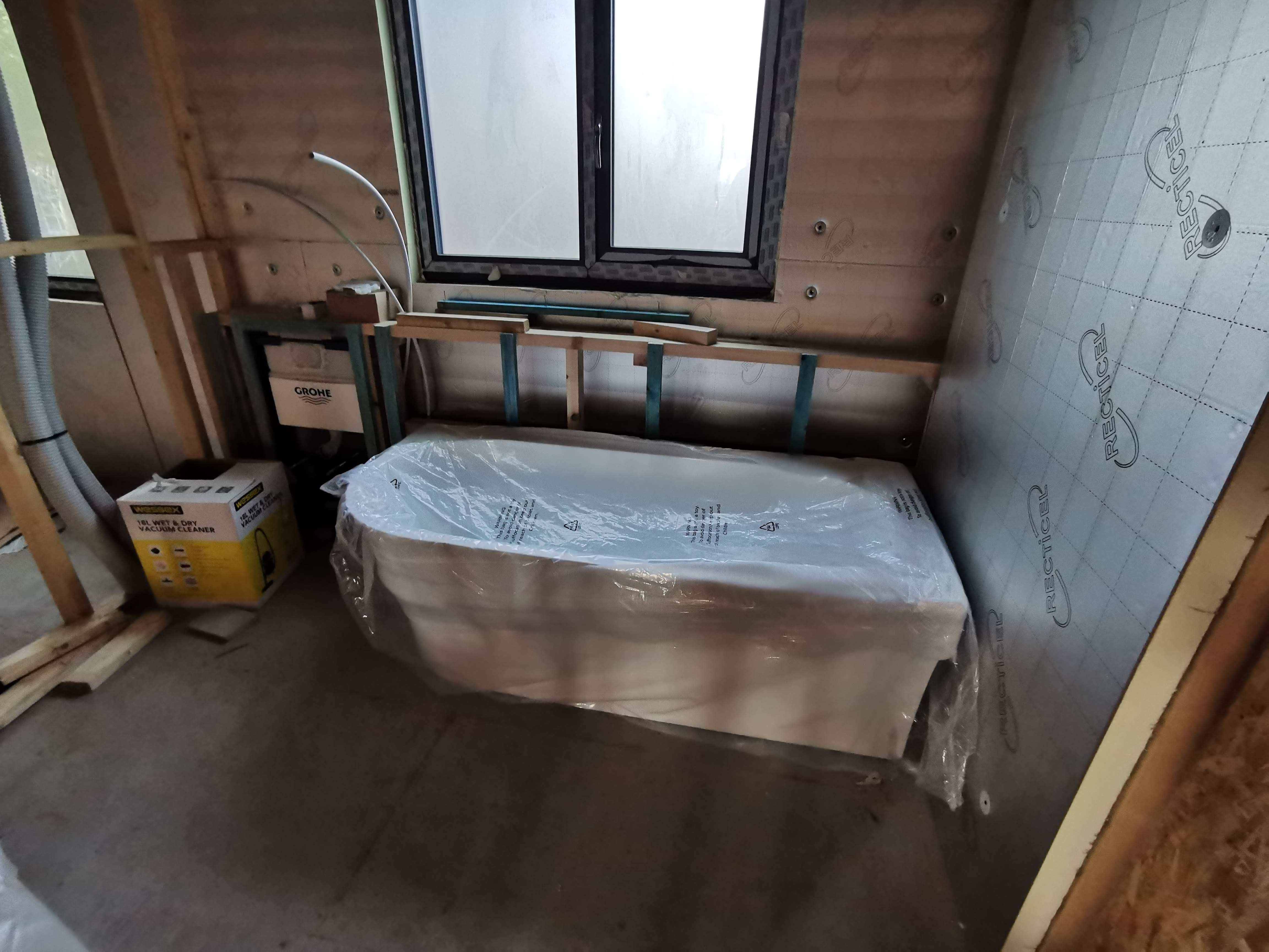
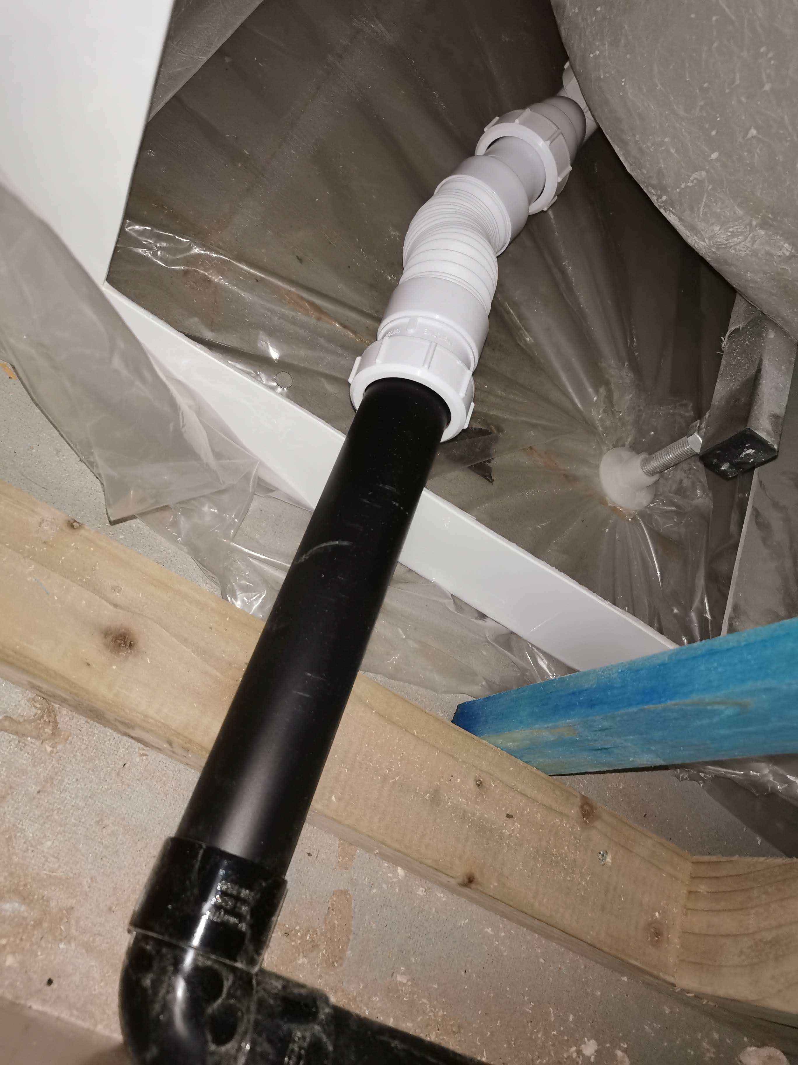
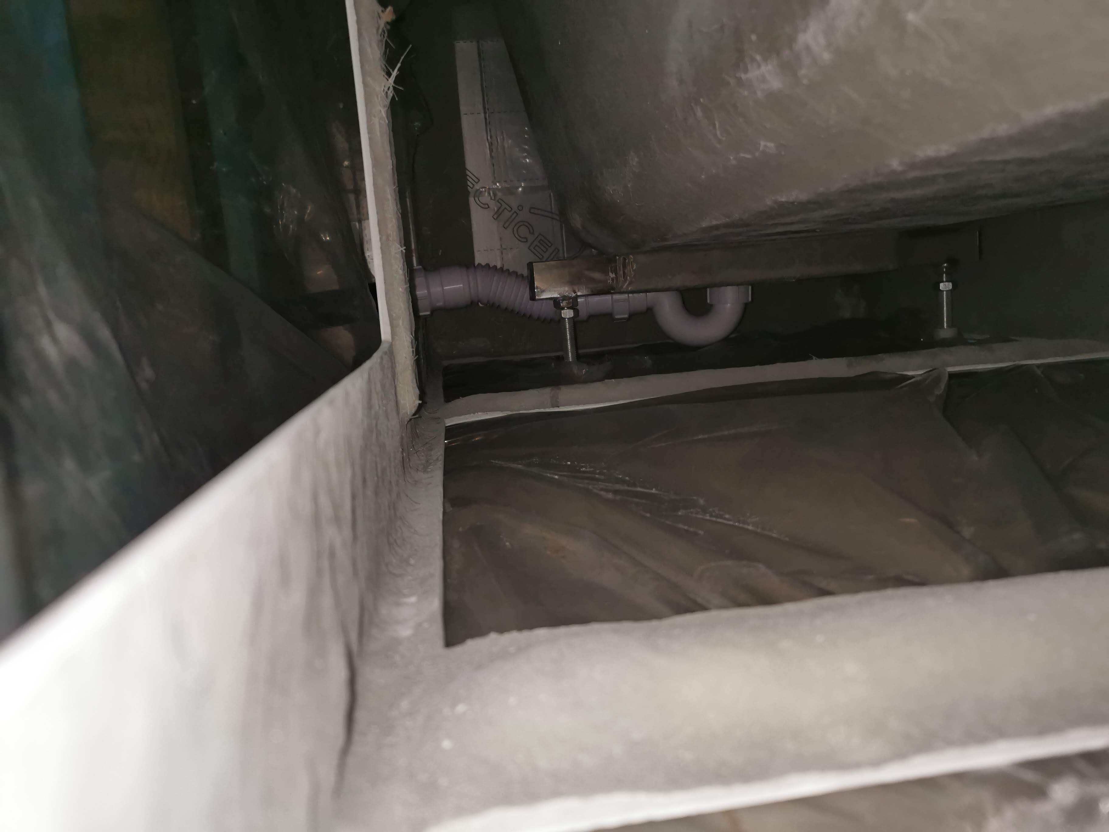
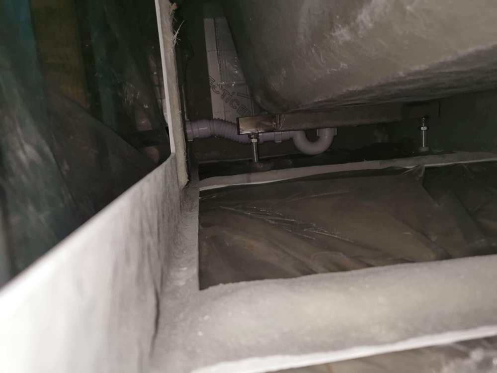
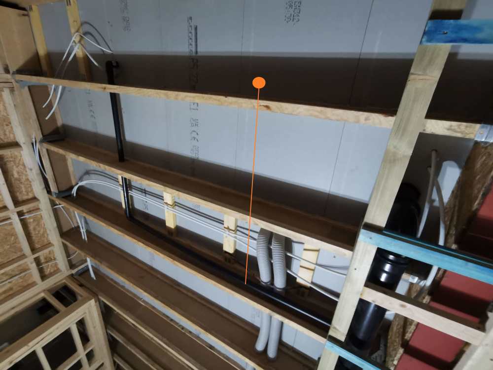
Hopefully the pictures should do most of the explaining here. It's a corner 'freestanding' style bath so no removable panels. Instructions show flexi waste through the floor. However our 1st fix for this room assumed a regular panel bath so the waste pipe for the bath has been installed alongside the bath rather than under the floor. Should I change this whilst I still can or will this (slight rise over lip of bath frame) likely be fine? Although photos show a short flexi adaptor (Flexcon6 I think), will have to use a longer one (Flexcon2?) as there isn't enough 'flex' to get your hands in to tighten the fittings with the bath at a suitable angle with this one. Can't see a way to avoid a flexi in this case either way, I guess same as a regular freestanding bath. Room - general view Slight rise as waste exits from under bath Flexible fitting Ceiling below (proposed thru floor to follow orange line


-
Where is your boiler/heat source? You might want to simplify pipe runs by keeping radiators closer to this area. Also depends on your beams - we've go I-Joists which have strict rules about cutting holes in the web - so routes have to planned around this. If you have open webbed joists it'd be a different story. Our architect placed the radiators under the windows. However this isn't really necessary. A good option tends to be on the wall as your walk into a room as you aren't going to want to put furniture there.
-
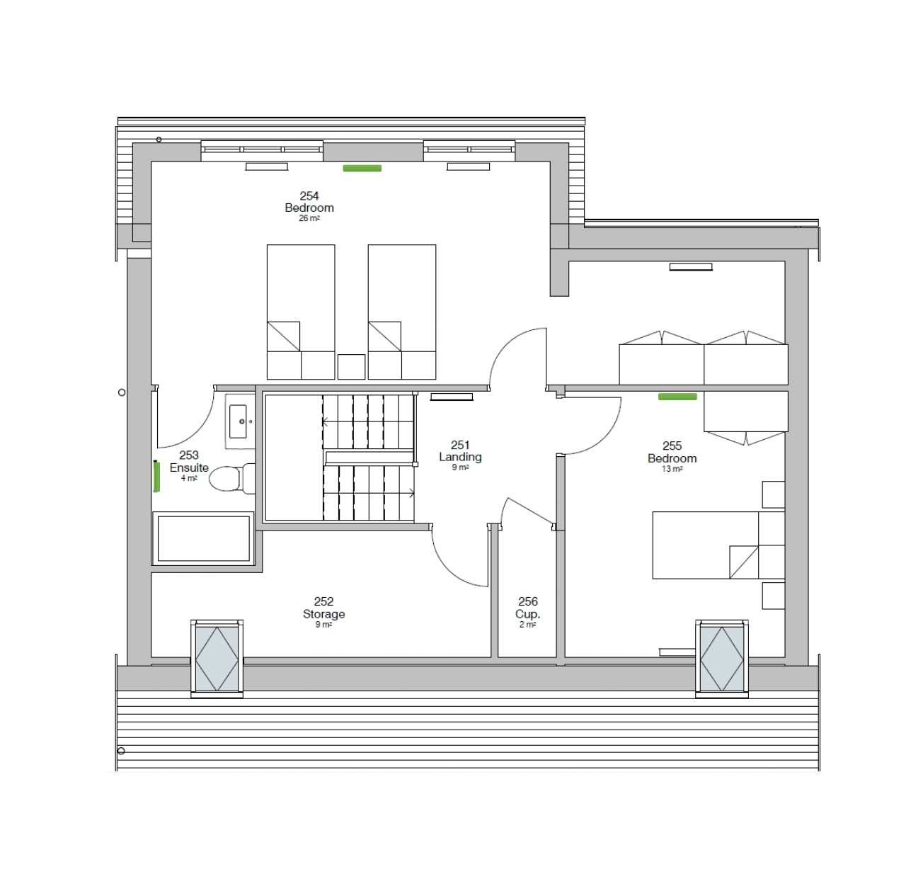
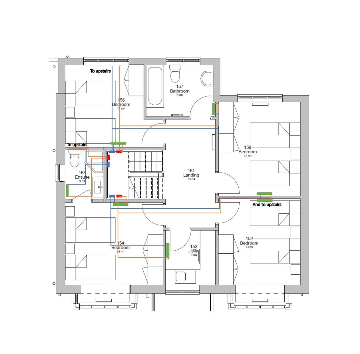
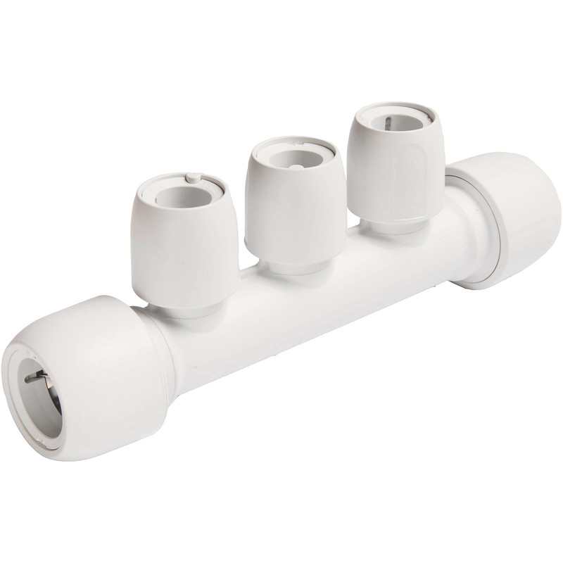
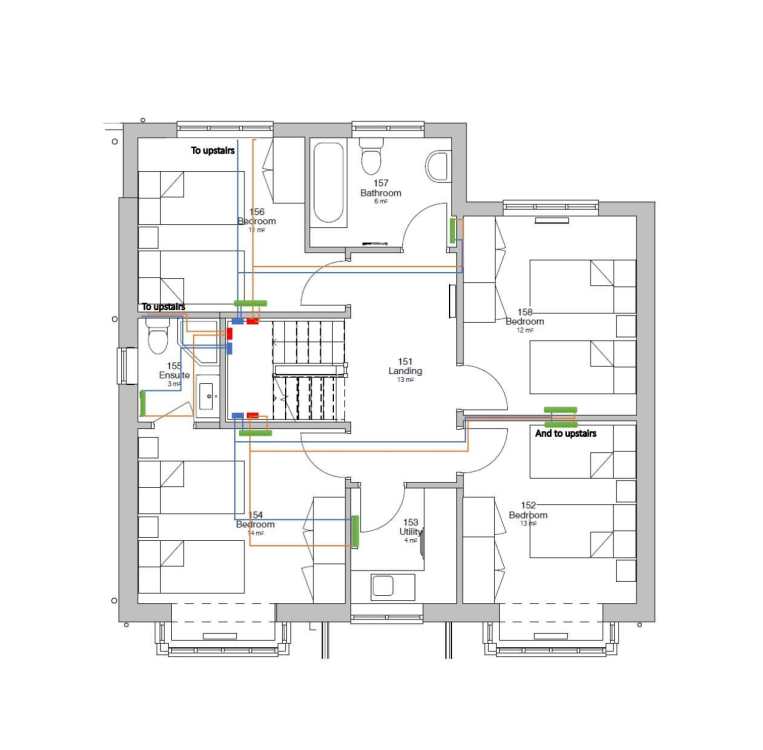
Would really appreciate some help with finessing my radiator plan before I start drilling holes… Hopefully some clarity here will help others in similar situations. Heating will be provided by a heat pump supplied and installed by British Gas. However, they do not do first fix apparently, so that’s down to me. They have sized the radiators (almost all small type 11 – mostly 400mm or 500mm wide though the widest is 800mm). We have 10 in total including 3x towel rads. All radiators are for upstairs only. We have UFH in the ground floor slab with a few spare ways in the manifold (installers decided to leave out a few circuits – but it is what it is). So, I could potentially run a few rads off the spare ways in the UFH manifold – not sure if that is a good idea or not? I know many on here have used the UFH type manifolds with separate runs to each radiator. However, this isn't ideal as we have I-Joists and MVHR so I have to be careful to keep the necessary distance from existing holes drilled in the joists. Coupled with a number of impassable glulam beams, it isn’t really an option to run pipes from each individual radiator back to a central manifold. So as a compromise I’m planning on around 3 pairs of flow/return coming off separate push fit manifolds. I would locate each manifold in the area below the stairs (centrally located in the house - see blue/red rectangles on diagram) on the side closest to the rooms they are feeding. These would be linked with 22mm plastic and reduce to 15mm at the ports. (This central area under the stairs is where the heat pump primaries would enter the house and where the UVC will go.) I’d then run a maximum four radiators off each 15mm flow/return pair. ChatGPT has helped with calculating flow rates and losses over different lengths of pipe. It claims that by adding additional flow/return branches, flow rates will be improved – rather than running say all 10 rads off one 15mm flow return circuit – which of course makes sense. I’d tee off these flow/return pairs in the void between the joists or in the stud partitions for each radiator. Does this sound reasonable?! Thank you. Planned manifold type 2/3/4 port depending on how many flow/return feeds (pipe to be pert-al-pert 15mm):


-
No airtightness tape detailing that I can see on their Standard Details PDF. The system is designed to have plasterboard fixed directly to the OSB. Airtightness is taken care of by overlapping and sealed giant T&G joints of the SIPS panels themselves. PIR is just for higher u-values. A breather membrane is fitted to the outside.
-
Perhaps for this reason (moisture getting trapped in outer osb layer) Kingspan TEK systems are built with PIR installed internally. The supplier we used has the u-value data for different thicknesses of PIR on this page https://www.clays.com/sips-technical-data
-
Is attenuation always required
MoDo replied to MoDo's topic in Energy Efficient & Sustainable Design Concepts
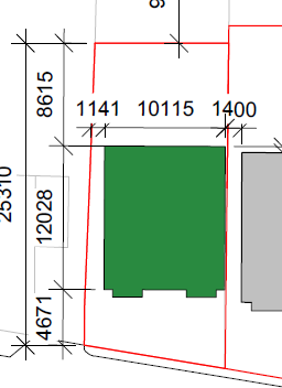
Right yes 1m3 makes sense - I used a larger impervious area in case permeable paving isn't suitable for some reason so got the slightly higher figure. Perhaps I just need to accept that this amount of storage will be required. Can't use a pond or anything like that - just isn't the space, will probably have to be those crates or some underground tank. I'm still wondering if we could simply argue that 1 or 2m3 of storage can be mitigated (avoided) by using permeable paving or something along those lines. I guess no harm to draft some sort of report any try it. Has anyone written their own report? Assume it needs approving by the local water authority prior to submitting to planning? -
Is attenuation always required
MoDo replied to MoDo's topic in Energy Efficient & Sustainable Design Concepts
Thanks, some interesting approaches. Yes the site slopes very gently so water likely already running off. However I get that we have to improve the situation not necessarily maintain it. I've done some calcs (well, the website tools do the calcs) using the Wavin and UKSUDS tools - both seem to indicate we'd need 2.5 - 3 m3 of storage which is minimal. I've no idea though if we'd get away with arguing that using permeable paving ought to be sufficient. -
Is attenuation always required
MoDo replied to MoDo's topic in Energy Efficient & Sustainable Design Concepts
Thanks all for the responses. I was deliberately brief, perhaps overly. Cutting a very long story short, we are picking up the pieces (on a pathetically limited budget) from a contractor who overspent and erred at seemingly every opportunity. This submission of compliance with a condition of planning being one of them (which we just discovered had never been approved) - as no drainage improvement information was ever submitted. My understanding is that SuDs and attenuation are distinct - I may be wrong - but on this assumption… Soakaways won't be possible - the site is too small and ground likely unsuitable anyway - we're in Manchester - very urban - no streams etc. The site is small, only a few meters to the road and almost nothing on the sides. So SuDs are unlikely to be viable (besides for the budget issue). The planning officer did also mention that it might be “possible to argue why SuDS cannot be incorporated into the scheme. However, it will still be necessary to demonstrate how existing surface water drainage rates will be reduced to existing greenfield runoff rates or 2l/s, whichever is greater”. The former part (in bold) leads me to believe that attenuation is non-negotiable (where runoff is increased beyond 2l/s) but that SuDs can potentially be omitted. Hence I'm left trying to calculate if a) we must have attenuation and b) how much do we need. I’ve been trying to work it out - mostly from this document https://assets.publishing.service.gov.uk/media/602e7158d3bf7f7220fe109d/_Rainfall_Runoff_Management_for_Developments_-_Revision_E.pdf but although I can see various tables titled “Attenuation storage volume as a function of QBAR/A and PIMP” I can’t work out which table to use! Building footprint is approx 12x10m if that helps to calculate the roof size (and thus run-off)? I should add the site was previously a dilapidated residential garage so we aren't increasing runoff - however it seems this is irrelevant - we cannot exceed 2l/s regardless. Here is the main part of the land registry location plan. If anyone can help (short of the firms charging £1600+vat) I’m more than willing to make a donation to the forum (though also willing to pay a reasonable amount if someone on here can help professionally) and would be grateful to PM any further info.