MarcelHoldinga
-
Posts
30 -
Joined
-
Last visited
Everything posted by MarcelHoldinga
-
Thanks all, We've not fired the stove yet, so I don't know how hot the flue gets, but it sounds like it should have had something fitted to prevent air blowing through the gap. The flue is an insulated (I hope) twin wall, so an airtight grommet might be an option, though it's all fitted. I'll have a look what my chances are of stuffing the gaps around the flue with fireproof rockwool.
-
Does anyone have any advise on retrofitting non-combustible insulation around the flue for a wood burner? It appears that when ours was installed, the installer left the 50mm gap to combustibles around the flue and didn't fill it any n/c insulation material. The result is that there is a lot of cold air blowing through the roof void and into the "warm" loft space, which in turn leads to cold air blowing through the light fittings in the ceilings of rooms below the loft. Everyone I've spoken to about this has said "Oh, that's just a necessary evil that you'll have to put up with", but having seen this thread, I'm wondering if anything can be done to seal up the 50mm gap around the sarking board and the layers below it, so we don't have the north-easterlies blowing nearly as strongly inside as they are outside (not to mention the heat loss)... The flue goes straight up through the vaulted ceiling/roof - the angle of the roof is around 20 degrees. Thanks in advance for any ideas!
-
Best option for replacing Honeywell T6360
MarcelHoldinga replied to MarcelHoldinga's topic in Underfloor Heating
Not sure if neutral is connected at the other side - I can contact the sparky who wired them up to see what he did (or didn't). They've always been unreliable... I just put it down to inconsistent materials used in making them... -
Best option for replacing Honeywell T6360
MarcelHoldinga replied to MarcelHoldinga's topic in Underfloor Heating
Thanks ProDave. The current wiring on the stats is in the attached picture - spoken to the electrician who wired them in yesterday, brown is live, black is the switched wire, grey is neutral and the earth wire is on the left. Does this look right? When you say 2 wire operation, does that mean that the thermostat is battery operated as far as display and controls goes, with the switching done using the live and switched wires? I'm not a fan of having to go around replacing batteries - isn't there an option for mains powered thermostats?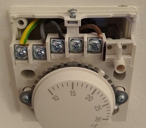
-
Hi there! I've got currently got 6 Honeywell T6360 dial thermostats that were installed as part of water UFH system (Daikin heatpump with DHW cylinder, and the usual manifold with actuators for each loop) and none of them appear to be working right, in that they appear to be set to switch on anywhere between 1 and 3 degrees below the temperature the of the room (i.e. with the room at 21 degrees C, the stat clicks on anywhere between 20 and 18 degrees), meaning they're driving the temperature up, unless I make a mental note of the individual offsets and compensate each room by setting the temperature lower. I don't have the mental capacity to do this - not because it's not there, but because I CBA to to this... Does anyone have any suggestions for good quality replacements that are not going to cost the earth? I've had a root around on the internet but there's so much choice and different makes/non-makes that it's kind of making my mind boggle! Thanks Marcel
-
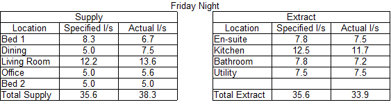
Thanks for that information, @DundeeDancer and @PeterStarck. I've been able to borrow an airflow meter off the installers. I did some measurements on Friday night and got the figures in the attached image. These are values at on the background extraction level (called At Home on our unit), with supply and extract fans both running 75%. The Specified column shows what was specified by Airflow at the design stage of the system, Actual is what I measured on Friday night. From reading @Jeremy Harris's post in Balancing MVHR - how to? by @readiescards (below), I noticed that the levels we have set as background extraction are quite close to the extraction levels you would expect at on boost... No wonder that the guy who installed it had remarked that he had to put the fans up to 75% to get the right flow rates... I'm beginning to suspec that we're working out unit too hard... Speaking to Airflow themselves, I learned that the boost supply and extract levels should be around 20% more at the valves than you would have on At Home.... Would it be right to assume that the system's been set up the wrong way around? From Jeremy's post, you start from Boost, and then work your way down to background levels, but the manual to our unit tells you to set the background level, and the unit then automatically increases the fans' output by 30% (e.g. At Home is set to 50%, the unit would automatically set Boost to 80%)
-
that second 28 boosted should have read 36 cu m/h boosted... missed the edit window - ?
-
Thanks @Stones, I will give that a go and see what I can unearth.
-
@ProDave re the high background ventilation rate, you're right - the boost profile would normally increase extraction by 30%, which means it should boost at 105%, so it's not extracting right. I've spoken to Airflow, who told me you should get 20% extra air flow at the terminals, but as it stands, we're measuring 13% extra on the boost profile in the bedroom. We've measured the flow rate there, it's 24.6 background and 28 boosted. The calculations for the spec of the system shows 30 background and 28 boosted...
-
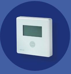
Supposedly 1.75 cu m/h/sqm (from a specified target of 5), but from what you've just said, that might not necesarily the case. the unit is a DETA wall mounted unit (pictured), it's mains powered, so I don't know how we'd go about calibrating it... I'll RTM and see whether that could be an issue.
-
We used a local builder, and from what I've heard everyone's very busy, so they're spreading themselves thinly on quite a few jobs, which makes things possibly take a bit longer than they otherwise would. Now that we're in, apart from some teething issues, it's slowly beginning to dawn what we've actually done!
-
They have, but I'm not too sure that they were set up right. The guy doing it can't have spent more than about an hour and a half on the whole house (4x supply and 4x extract valves) - I;ve read on another blog that it could take the best part of a day to get it right... I suspect it was windy when they set it up, 'cos I've noticed that if it blows a hoolie, the levels stay low (in the 400s while we're asleep). I'm hopefully able to borrow an anemometer off the company who installed it, so I can double check the rates and (hopefully) adjust them. The installers only installed the system, they didn't supply or design it...
-
Intake and exhaust are around 2m (6'6") apart on the west face of the house (the high part of the mono-pitch) bedroom door is ajar, as is the door to the ensuite (extraction point) CO2 monitor is wall mounted and doesn't look like it can be removed...
-
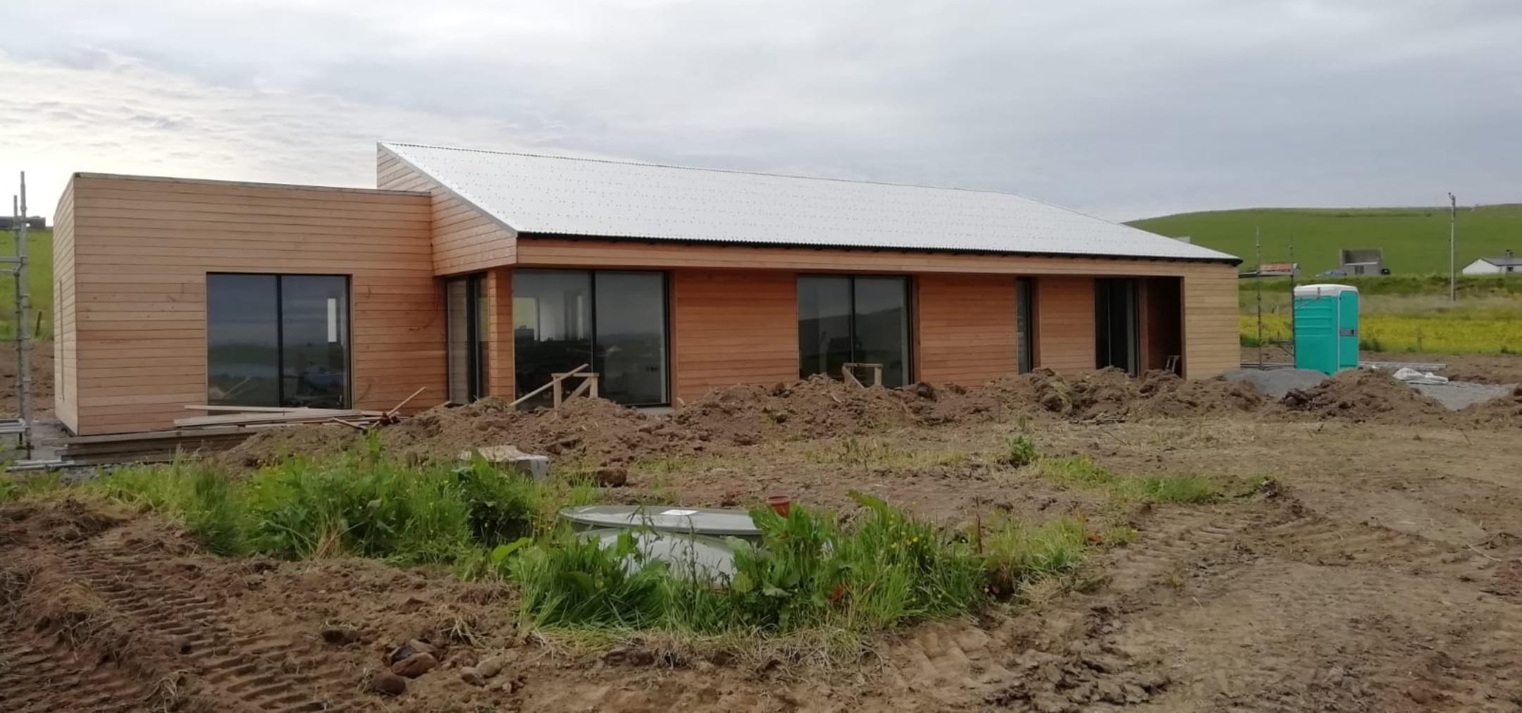
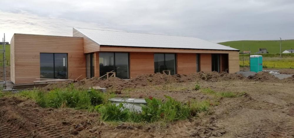
I've just realise that I just barged in asking loads of questions, so I reckoned I'd better introduce myself... ? I'm Marcel (as you might have guessed from my username), and my other half (Joanne) and I have been in the lucky position to be able to build our own house in Orphir in Orkney. ...well, I say we built our own house, we had someone do it who has more experience at this game than either of us does... We moved to Orkney 5 1/2 years ago after falling in love with it on a holiday a number of years before that. In 2014 we were both made redundant from the jobs we were at (don't worry, it was voluntary), and we had always had the dream of one day building our own... During the design and build stages, we've stayed in a few places, but we moved in in September. This is the result of our little project, minus the portaloo. It's a 2 1/2 bed ICF built larch clad bungalow, with an Air to water heatpump and MVHR. (edit because I hit Post before I was done... ?)
-
Me again, this time I've got some basic questions about MVHR... We have an Airflow Adroit DV96 MVHR unit (one of the earlier units without onboard CO2 sensing), with radial distribution using Airflex Pro ducting. We have a CO2 monitor in the main bedroom (unfortunately, it's not a sender for the MVHR unit) and I know there are certain levels at which the unit will show a green, amber or red light, though I'm not quite sure at what levels it would change from one to the other... With the MVHR unit on the standard setting (running at 75% of max power), we were getting the of 1300+ PPM as the maximum. I've set the unit to run the boost profile a number of times during the night, to compensate for the fact it can't increase air flow automatically (lack of CO2 sensing capability), and we're still going up to around 1100 PPM... My question is: what sort of CO2 levels can you reasonably expect to see overnight in a bedroom with properly functioning MVHR?
-
@PeterW ASHP is Daikin Altherma. Outside unit model number ERLQ008CAV3, Interal unit model EHBH08CB3V. We've a 300 litre DHW storage tank, which is set to 45 C.
-
I noticed it at 32C at one point the other day (UFH had been off for a while) then made a point of checking when I knew the UFH was running, and it was near the 38C setpoint on the internal ASHP Module. I've since reduced the LWT temp to 36 - intending to knock it down some more.
-
it's a warm space - insulation is in the roof, so fingers crossed shouldn't freeze up I'l have a look and get back to you on the heatpump model
-
There's no insulation on the long DHW runs either, which I found odd... some of it sits directly behind plasterboard, so possibly no space for it, but there's a section in the loft where it could [read: should have been] fitted. Wouldn't having a bypass on the manifold negate the need for an open loop somewhere in the house? Afaik, when all the stats are off, the system won't call for heat. I've turned them all down to 17 or 18 degrees and it's been comfortable.
-
yes, separate settings for UFH and DHW - UFH currently on 36C, DHW is at 45C
-
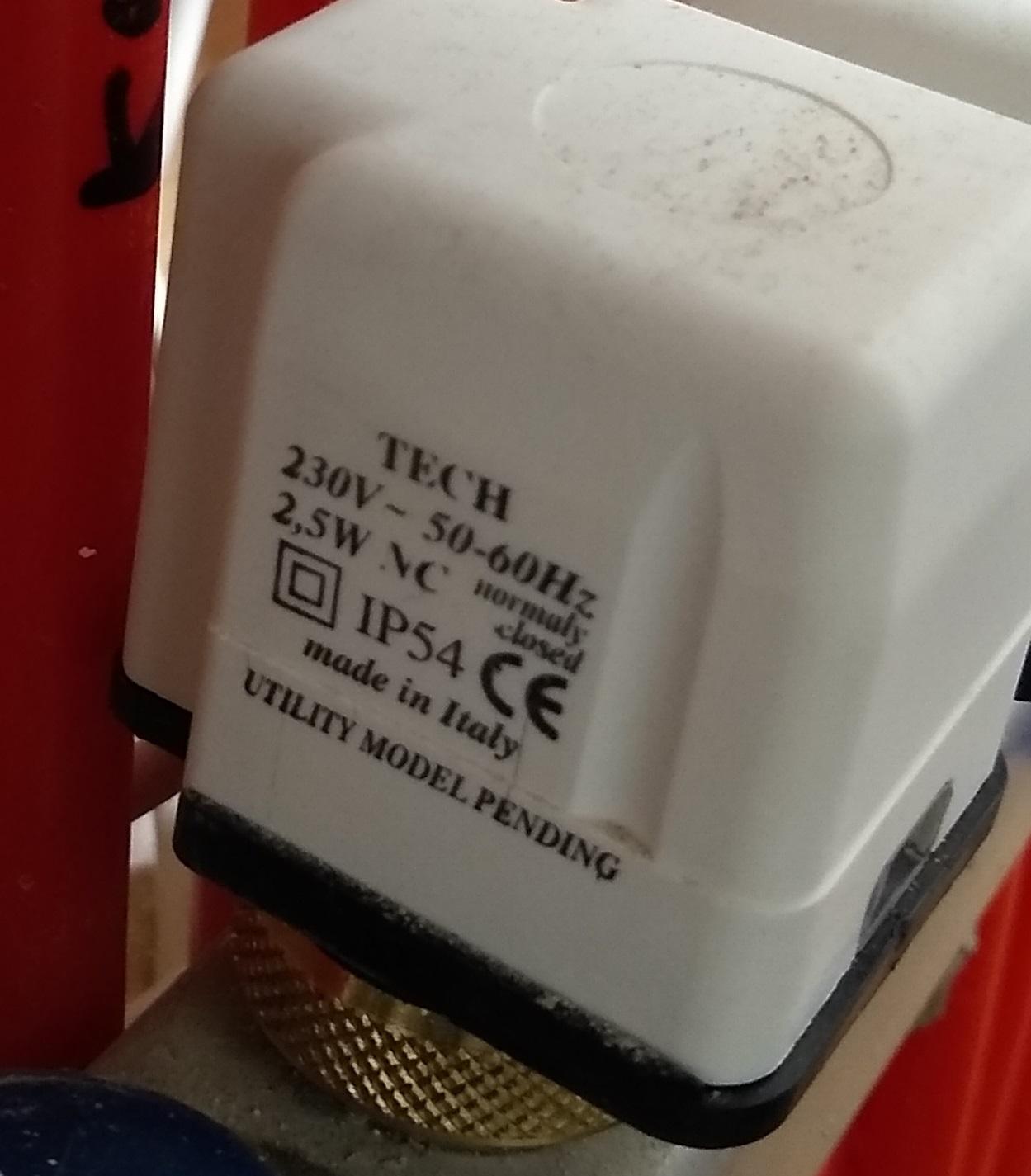
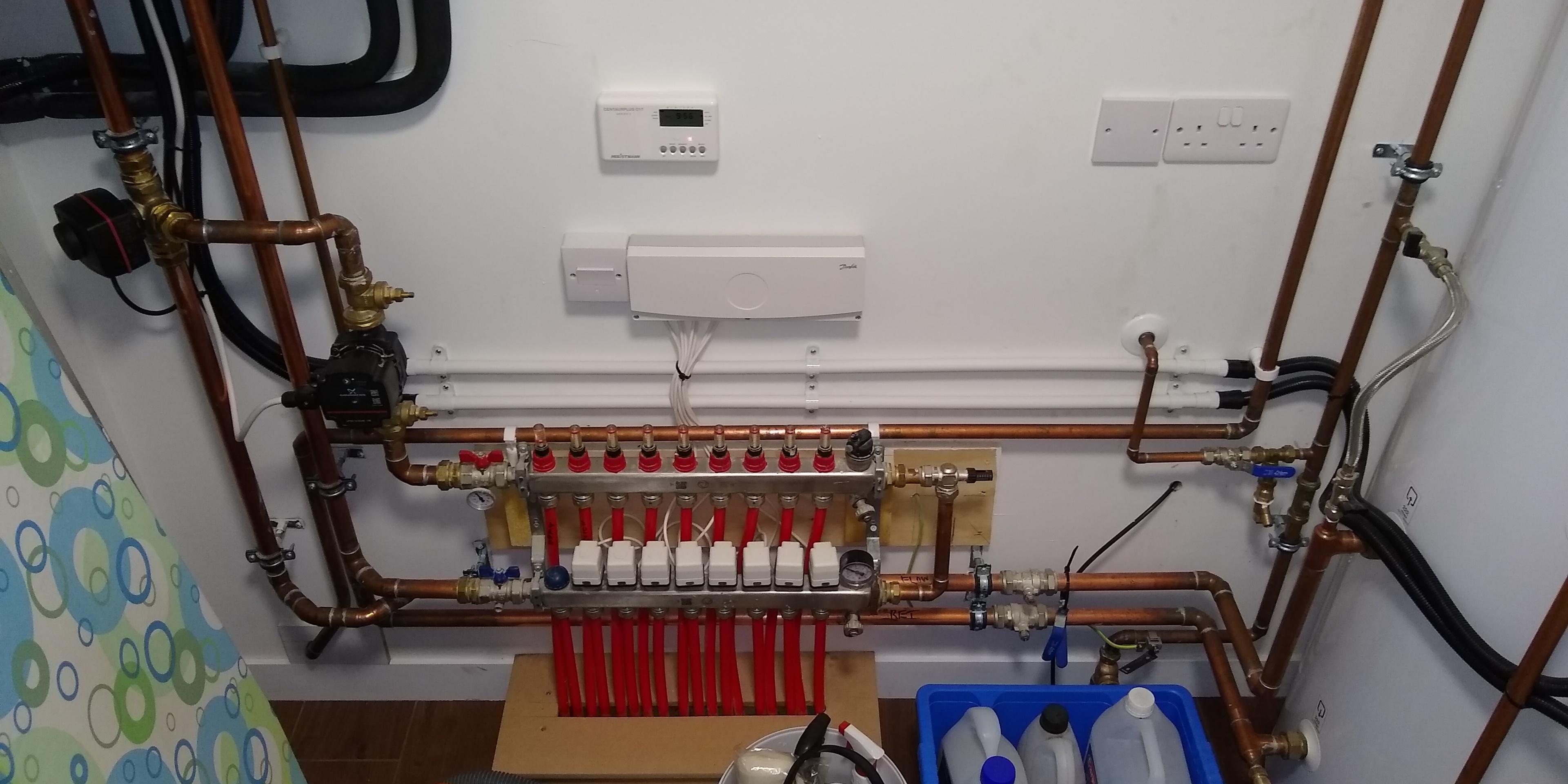
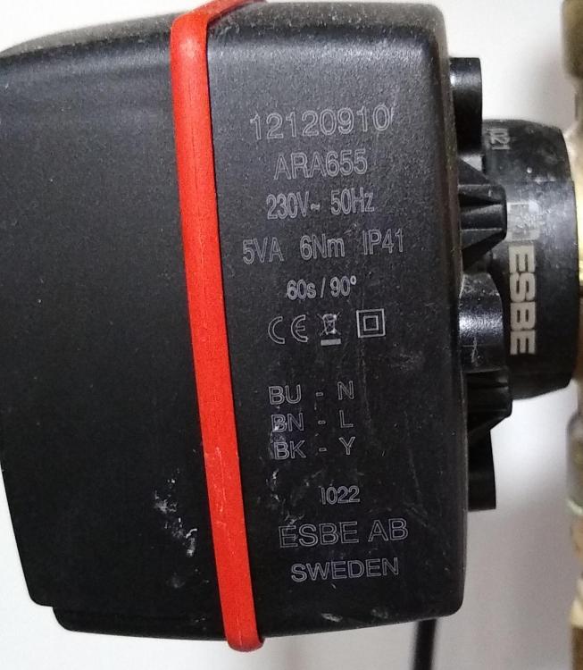
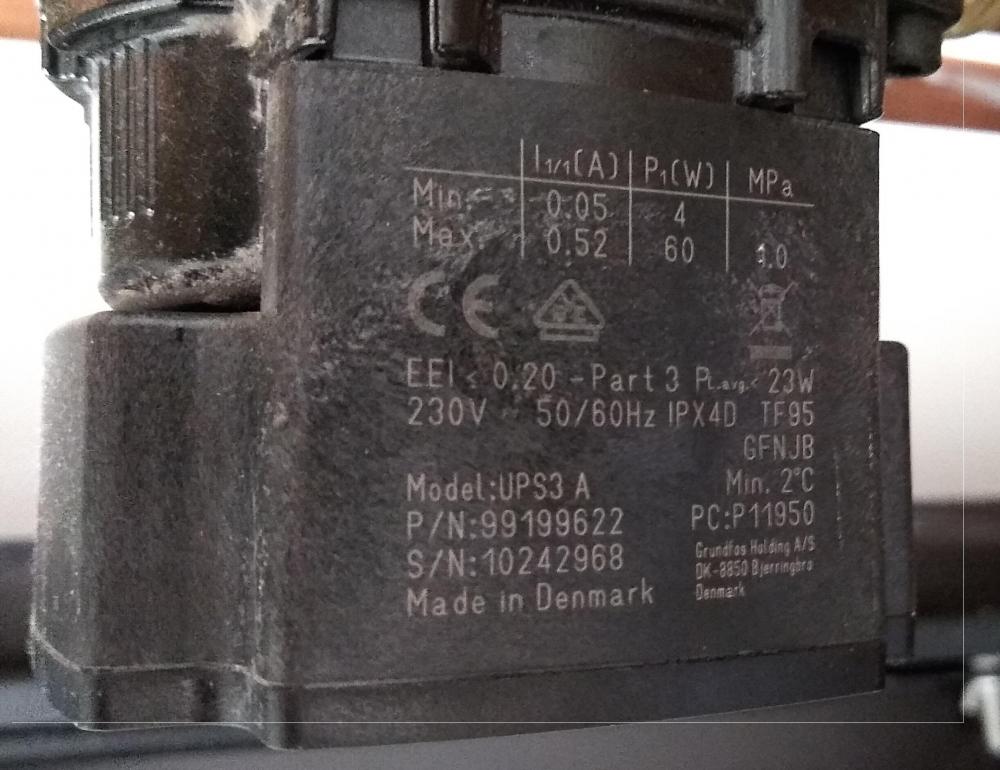
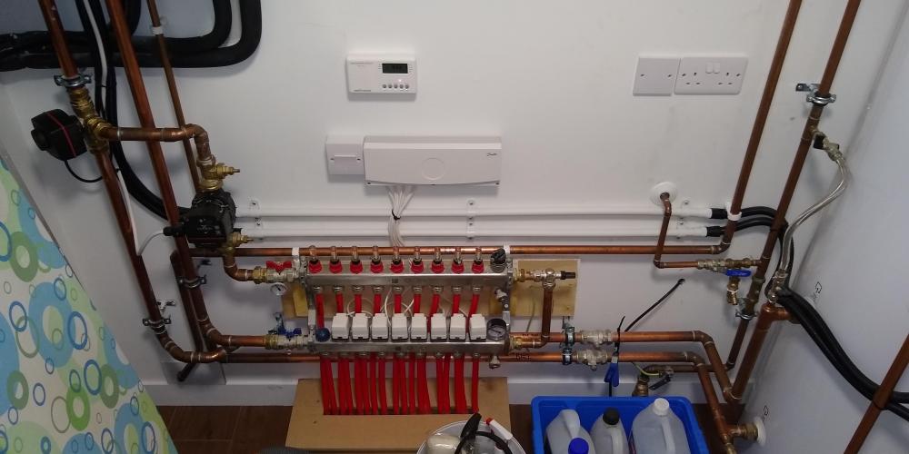
ASHP has got temperature setting - nothing fancy, just a simple, single temperature - it looks like any advanced methods of controlling UFH temp have been switched off by the installer Images of diverter valve (red line, on the left), UFH circulation pump (middle) and actuator valves on manifold (right). The loop on the left (blue cap) is an open loop to the main bathroom - if there's a bypass, I'm not enirely sure why this would be there. The installer said that your bathroom is usually the hottest room in the house, and that there would normally always be an open loop into there... I've got a pic of all the destinations on the manifold pipes somewhere, but I'd need to have a look for that and post that later, 'cos I'm at work at the moment...

-
This is our setup, internal ASHP is on the left, DHW tank on the right. I know the left hand black unit on the pipes diverts water either to the UFH od DHW, with the one attached to the manifold being the UFH circulation pump, but other than that, can you tell I'm fully clued up? ?
-
Not aware that I do - would it be obvious from looking at the various pipes/manifold?
-
Not sure it does - it does have separate controls for LWT (UFH) and DHW; UFH was set to 38 (reducing that slowly) and DHW is currently set at 45, with a sanitising run once a week to keep legionella at bay. It appears the unit was set up with just the basic settings available to us LWT temp up and down, no weather compensation or any of the fancy modes that Stones mentioned in his post...
-
Cheers, Temp. I'll have a look at the weekend - my home life is still disrupted by work these days.