


B52s
-
Posts
62 -
Joined
-
Last visited
B52s's Achievements
Member (3/5)
13
Reputation
-
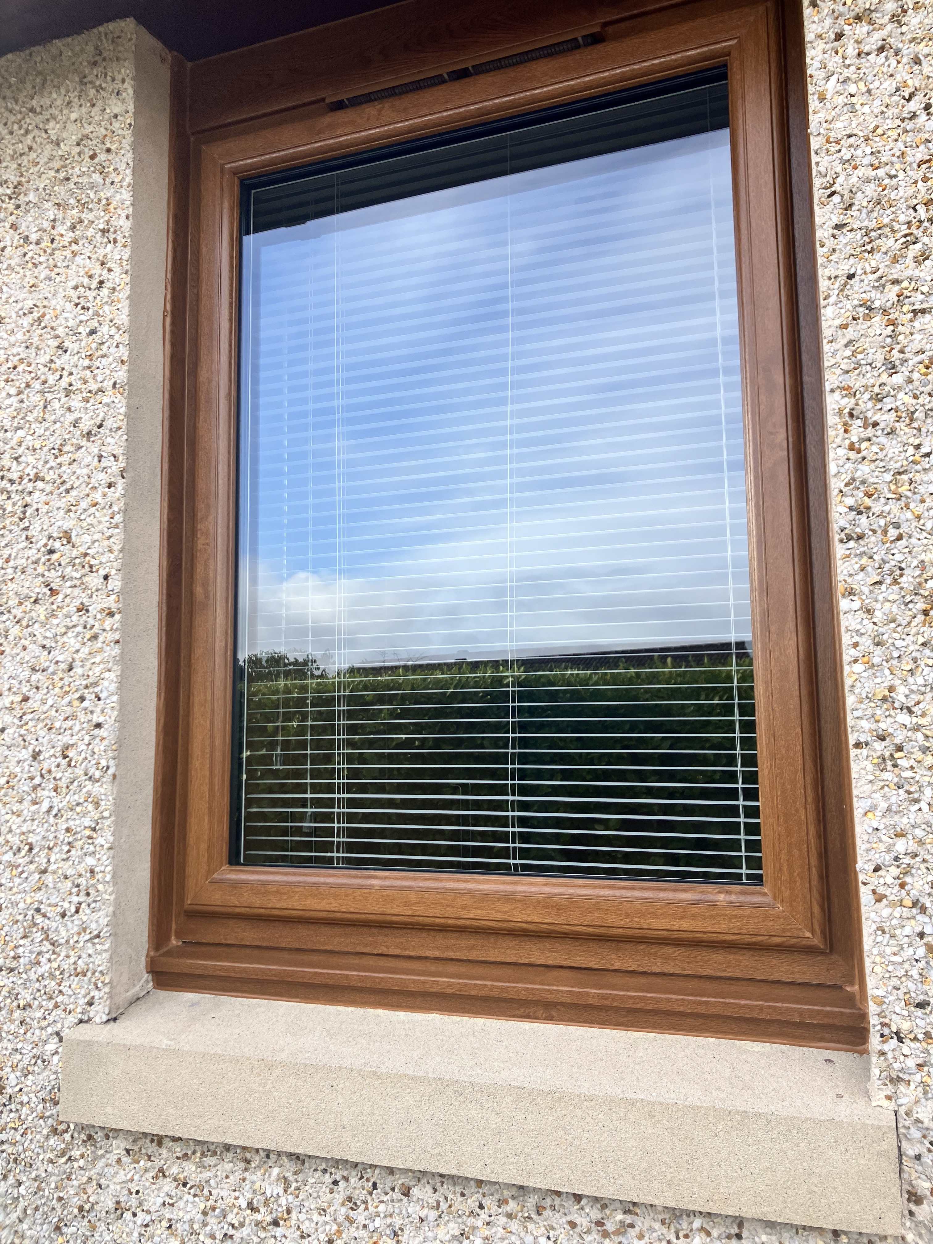
 Just a wee update Nick, I followed through with your suggestion about the dummy cill and all windows look sooo much better now. The installer was quick to sort it out to my complete satisfaction. It's just a pity I had to go through the pain to get this done when this should have been included in the install, rather than having to get the installer back to complete the work properly.
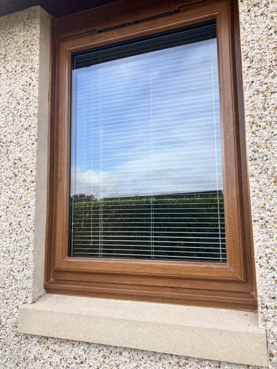
-
Your point is noted Nick. We did have an amicable solution, it was me doubting the agreed solution that has prompted my post here looking for advice, and I'm glad I did. Thanks to you I can go back to the installer and advise that I have had a change of opinion and would like to suggest the uPVC dummy cill in lieu of the cement option. The installer was unable to proceed with the cement option because he was rained off and that's what gave me time to give careful consideration to what I had previously agreed to. This "thinking on your feet" business can disadvantage the customer (me) into agreeing to a solution in the absence of any independent technical advice. Thanks again Nick for your input.
-
Thanks for that Nick, that makes perfect sense. Not paid the installer yet, so still have a firm grip over him. The installer has been back and few times to sort out some other snagging issues, so he's a wee bit on the backfoot at the moment. The T&Cs are in my favour as payment is not due until the customer is satisfied. As I said above, the large installer has a proven track record in my area.
-
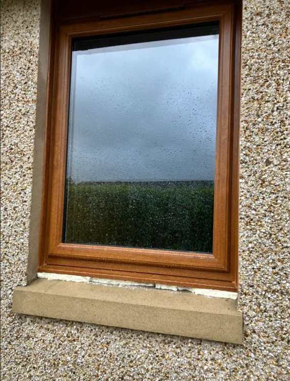
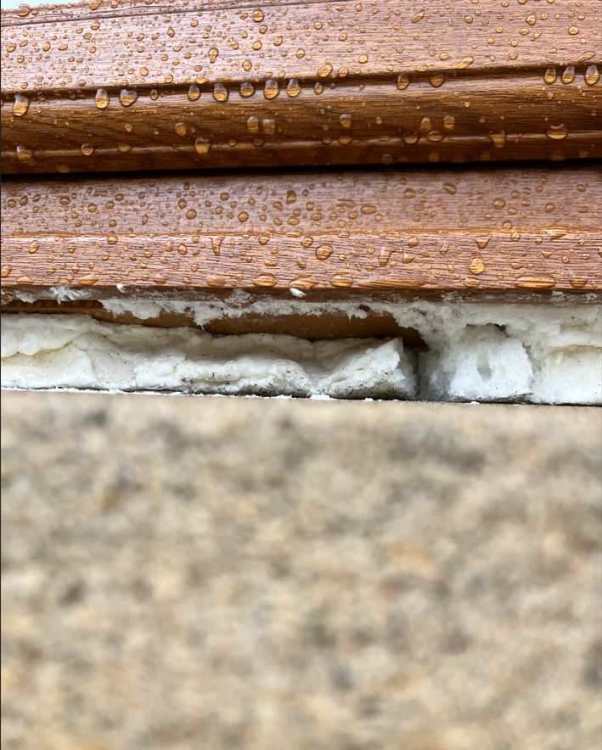
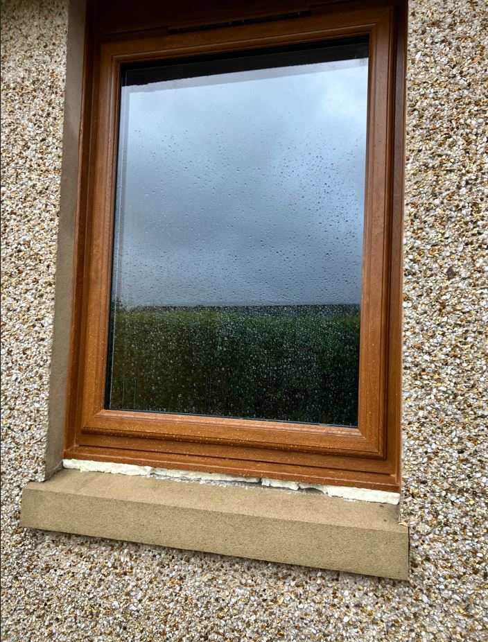
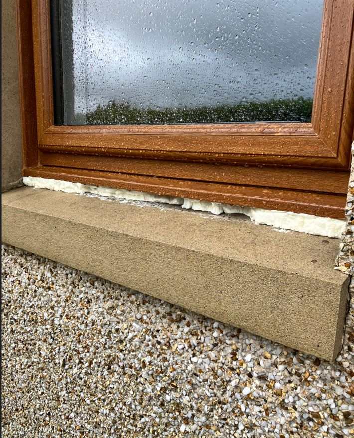
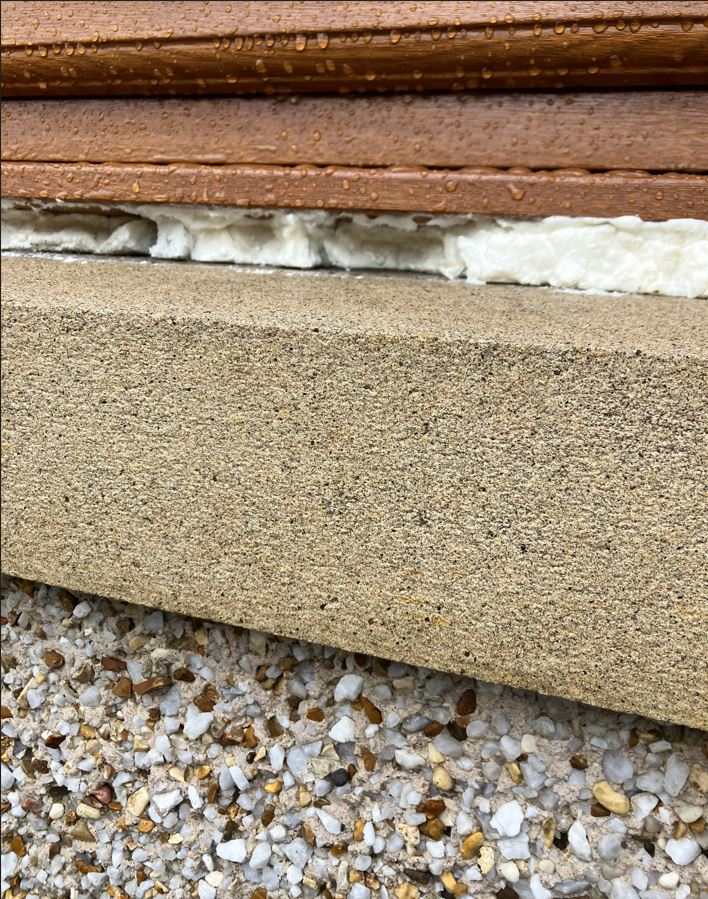
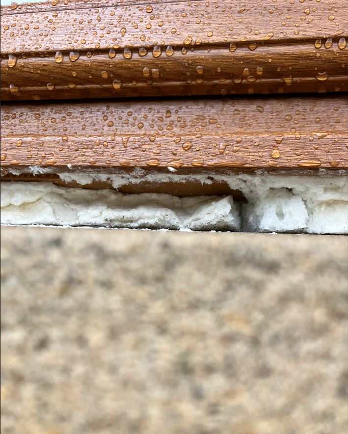
I'm looking for some advice to get the best technical performance and aesthetically pleasing solution to a problem, as I'm starting to lose confidence in the reputable window installer who may not be giving the best guidance and honest answers. I have recently contracted a local double glazing company (good local reputable installer), but I'm not happy with the actual install which has created a 25mm gap between the bottom edge of the uPVC window frame and the concrete sill. The previous timber uPVC windows had a discrete metal trim that fitted neatly between the window frame and the sill which made the windows aesthetically pleasing. The installer has given me two options; 1) Leave installation with the 25mm gap, which I'm told, will not result in water ingress as the window sits on the rear (concealed) raised edge of the angled sill inside the wall, albeit I think strong winds could drive rainwater under the uPVC sill, which is evidenced from 'capture 05' pic below. However, I'm also concerned about the impact this gap might create in terms of the thermal performance of the timber frame structure. Furthermore, the bottom edge of the uPVC window frame is straight where I would have expected this to be bull-nosed? Lastly, I just feel leaving a gap just looks bad. 2) At the moment, I have agreed to the second option, albeit I do have an opportunity to reverse this decision. The installer has filled the gap with expanding foam and it going to return with a builder to fill the gap with 25mm cement pointing positioned slightly behind the edge of the uPVC sill. I'm just not sure how this will look, but probably the best out of a bad situation? I'm increasing becoming concerned that what has been designed and installed (by the reputable installer) is not actually fit for purpose? Your thoughts on the best way forward would be very much appreciated, TIA


-
Advice required: Increasing existing window opening to take bifolds
B52s replied to B52s's topic in General Structural Issues
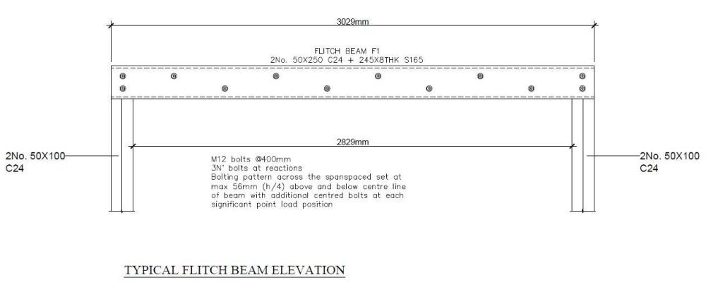
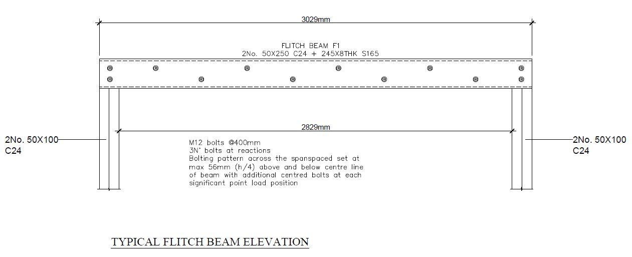
Thanks Gus Potter and ETC for your helpful input. I have received an updated structural drawing from the architect this morning (with revised Detail D1 and an elevation detail showing the flitch beam and goal posts). It would appear that things are now falling into place, if you can forgive the unintended pun.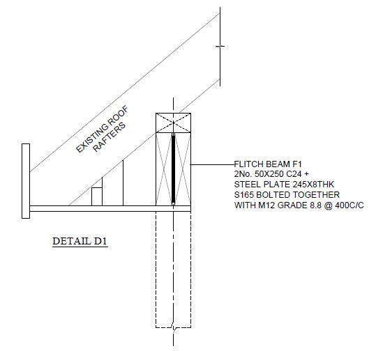
-
Advice required: Increasing existing window opening to take bifolds
B52s replied to B52s's topic in General Structural Issues
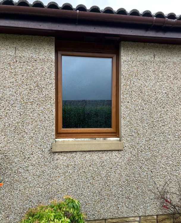
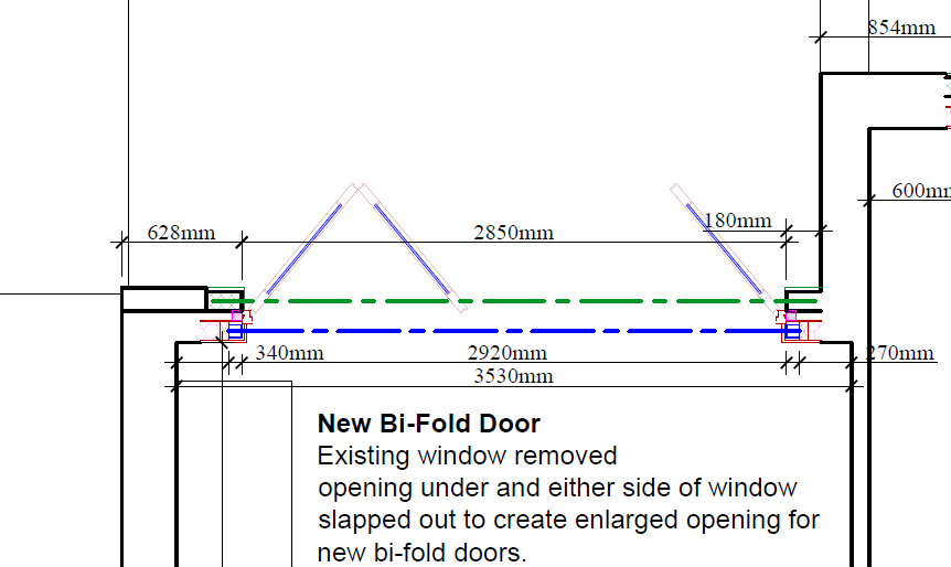
Thanks Mr Punter, yeah, if the wider opening requires a flitch beam, then I can accept that. It appears to be over-engineered (in my opinion) but that seems to be the way of things in terms of today's structural design requirements. With regard to the Naylor lintel, I would have thought that the top of the doors might be better being been finished in timber cladding to match the existing window openings. See below photo showing the existing 1800 window which is to be replaced by the bifolds..thumb.jpg.7f4d5effe2e1a917110fe3ce7815dab1.jpg)
-
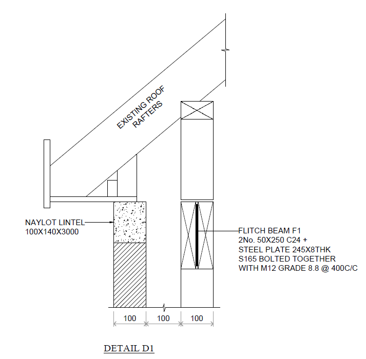
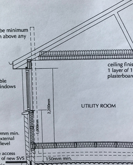
Guys, I could do with a bit of advice as I am doubting the structural details provided by my appointed Architectural & Structural Engineering Practice. My only point of contact is the architect who seems reasonable to deal with. The first issue I had was on Detail D1 (below) that shows a Naylot lintel across the top of the non-loadbearing block outer skin (timber framed house). The architect agreed with me that this was not required and said that this was merely a standard detail that has been added to the drawing by the SE and is not applicable in this situation. I can sort of accept that as a reasonable answer. The second issue was the location of flitch beam F1 positioned directly below the existing horizontal roof support (as shown in Detail D1). I pointed out to the architect that the flitch beam can’t be located below the existing horizontal roof support as this would be in conflict with the bifold door opening height. He said he would speak to the SE to see what could be done; I’m still waiting to hear back from him. He went on to say that the builder would sort this out on site, which puzzled me a little. However, in reflection, I’m now seriously questioning the reason for adding the flitch beam in the first place. The current 1800 window sits below the underside of the existing horizontal roof (truss) support as shown on the photo (below) of the existing arrangement. This opening is to be widened to 2850 to accommodate the proposed bifold doors. I can understand that 2 or 3 of the existing 95x45 vertical studs will have to be removed and therefore an alternative vertical support arrangement will be required, but surely this should not require the addition of a flitch beam, or am I being a proper “doubting Thomas” and should just accept that the SE knows best?, after all, structural calcs have been done which apparently support the need for a flitch beam with goal post supports. Any advice/thoughts would be very much appreciated.
-
fascias, soffits, guttering help
B52s replied to sarah barrows's topic in General Construction Issues
Okay, that takes me full circle back to aluminium as suggested by JSH. -
fascias, soffits, guttering help
B52s replied to sarah barrows's topic in General Construction Issues
I don't think the concrete interlocked tiles are nailed down. It was my understanding that the tiles are merely laid (interlocked) on the roof? Because the gable end tiles are cloaked verge tiles I assumed that they were designed to suit various roof sizes and therefore will have a degree of tolerance/float to enable the cloaked verge tile to be positioned to suit each particular roof. But perhaps the interlocking tile profile does not provide the movement that I was expecting. -
fascias, soffits, guttering help
B52s replied to sarah barrows's topic in General Construction Issues
PeterW, I'm swinging back to your suggestion of moving the tiles. After doing a little digging I believe the tiles on the gable end are called concrete cloaked verge tiles. Do you think it would be possible to prise (drag) the tiles away from the current timber fascia board (gently using a bolster or pinch bar) by about 7mm to allow a 9mm uPVC fascia overcladding to slip underneath, or would I be in danger of stressing the tiles which might result in hairline fractures at some future date? Your further thoughts would be appreciated. -
fascias, soffits, guttering help
B52s replied to sarah barrows's topic in General Construction Issues
JSH, that sounds a good option that I hadn't considered! ...I would be grateful if you could you point me to any websites where I can purchase the required materials? I don't really want to cover the existing soffit boards, as over the 20 years + I have been in the house, they have shown no signs of deterioration, albeit I did re-paint them 2 years ago, although i didn't feel this was necessary at the time. I just want a returned lip on the over-cladding that returns about 20mm neatly under the bottom edge of the fascia board. PeterW, I don't want to touch the roof tiles as I feel this could lead me into problems that would be beyond my capabilities, also, I have this issue on all four of the gable ends so I feel this would be a mammoth task, for me anyway. -
fascias, soffits, guttering help
B52s replied to sarah barrows's topic in General Construction Issues
I'm looking to (DIY) install uPVC over-cladding on top of existing sound fascia boards in order to reduce future high level maintenance (re-painting every 3 years or so). I'm looking for some advice on how to finish off the over-cladding on the gable-ends where the over-cladding will butt against the underside of the concrete roof tiles. I see this as potential weak point which could result in rain ingress due to the uneven profiles on the underside of the roof tiles. I was considering a line of silicon mastic where the two surfaces meet, but I am not sure if this is the best way to tackle this issue, particularly given that mastic should be replaced every 5 years to maintain integrity, which seems to defeat my goal of having zero high level maintenance. For information, I have attached some photos which shows the existing timber facia and the underside of the roof tiles.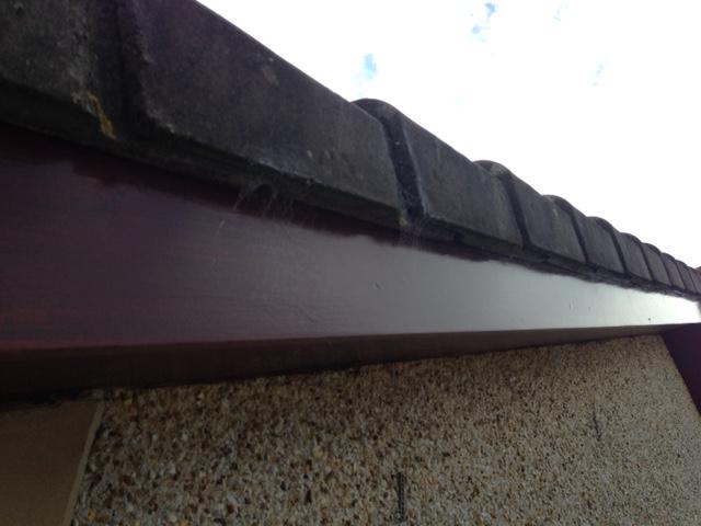


-
Lifting and Lowering (useful "rule of thumb")
B52s replied to B52s's topic in Project & Site Management
Just read an interesting article on US workforce fatalities. To para-quote; "The report also showed that 35% of all workers killed in 2015 were aged 55 or older. The largest federation of trade unions in the US said that over-65s were 2.5 times more likely to die at work than their colleagues". -
Lifting and Lowering (useful "rule of thumb")
B52s replied to B52s's topic in Project & Site Management
Yeah, I have always been amazed to watch "good tackers" single handed fixing full sheets onto ceiling joists. -
Lifting and Lowering (useful "rule of thumb")
B52s replied to B52s's topic in Project & Site Management
I believe "pressure" is being applied to plasterboard manufacturers to move to half sheet sizes, which again is sensible, but I understand this presents challenges in respect of modular timber framing, etc., ...but I'm sure it will happen in the fullness of time.


.jpg.19ad926b6b4ba74f226e1b6a01a777de.jpg)